EP1054573A2 - Dispositif pour le couplage mécanique d'un transducteur électromécanique de prothèse auditive implantable dans une cavité dans la mastoidite - Google Patents
Dispositif pour le couplage mécanique d'un transducteur électromécanique de prothèse auditive implantable dans une cavité dans la mastoidite Download PDFInfo
- Publication number
- EP1054573A2 EP1054573A2 EP00105203A EP00105203A EP1054573A2 EP 1054573 A2 EP1054573 A2 EP 1054573A2 EP 00105203 A EP00105203 A EP 00105203A EP 00105203 A EP00105203 A EP 00105203A EP 1054573 A2 EP1054573 A2 EP 1054573A2
- Authority
- EP
- European Patent Office
- Prior art keywords
- coupling
- coupling element
- transducer
- point
- cavity
- Prior art date
- Legal status (The legal status is an assumption and is not a legal conclusion. Google has not performed a legal analysis and makes no representation as to the accuracy of the status listed.)
- Granted
Links
Images


Classifications
-
- H—ELECTRICITY
- H04—ELECTRIC COMMUNICATION TECHNIQUE
- H04R—LOUDSPEAKERS, MICROPHONES, GRAMOPHONE PICK-UPS OR LIKE ACOUSTIC ELECTROMECHANICAL TRANSDUCERS; ELECTRIC HEARING AIDS; PUBLIC ADDRESS SYSTEMS
- H04R25/00—Electric hearing aids
- H04R25/60—Mounting or interconnection of hearing aid parts, e.g. inside tips, housings or to ossicles
- H04R25/604—Mounting or interconnection of hearing aid parts, e.g. inside tips, housings or to ossicles of acoustic or vibrational transducers
- H04R25/606—Mounting or interconnection of hearing aid parts, e.g. inside tips, housings or to ossicles of acoustic or vibrational transducers acting directly on the eardrum, the ossicles or the skull, e.g. mastoid, tooth, maxillary or mandibular bone, or mechanically stimulating the cochlea, e.g. at the oval window
-
- A—HUMAN NECESSITIES
- A61—MEDICAL OR VETERINARY SCIENCE; HYGIENE
- A61F—FILTERS IMPLANTABLE INTO BLOOD VESSELS; PROSTHESES; DEVICES PROVIDING PATENCY TO, OR PREVENTING COLLAPSING OF, TUBULAR STRUCTURES OF THE BODY, e.g. STENTS; ORTHOPAEDIC, NURSING OR CONTRACEPTIVE DEVICES; FOMENTATION; TREATMENT OR PROTECTION OF EYES OR EARS; BANDAGES, DRESSINGS OR ABSORBENT PADS; FIRST-AID KITS
- A61F2/00—Filters implantable into blood vessels; Prostheses, i.e. artificial substitutes or replacements for parts of the body; Appliances for connecting them with the body; Devices providing patency to, or preventing collapsing of, tubular structures of the body, e.g. stents
- A61F2/02—Prostheses implantable into the body
- A61F2/18—Internal ear or nose parts, e.g. ear-drums
- A61F2002/183—Ear parts
Definitions
- the invention relates to a device for mechanically coupling a mechanical one Vibrations excitable output-side converter part outside of the Middle ear area in an artificial mastoid cavity implantable electromechanical Hearing aid converter at a preselected coupling point on the ossicular chain, the Stirrup footplate or a round window or an artificial window in the Cochlea, in the vestibule or in the labyrinth (organ of balance) Membrane, with a biocompatible, mechanically passive coupling arrangement, which with the output-side converter part is connected and which in the implanted state of the mastoid cavity extends into the tympanic cavity as well as with one of the hearing aid transducers remote coupling end rests on the coupling point.
- Implantable hearing systems differ of conventional hearing aids: although the sound signal is with a transducer (Microphone) converted into an electrical signal and into an electronic one Signal processing stage reinforced; however, this amplified electrical signal will not an electroacoustic transducer (loudspeaker) fed, but an implanted electromechanical transducer, its mechanical vibrations on the output side directly, i.e. with direct mechanical contact, the middle or Inner ear can be supplied or indirectly by frictional connection over an air gap in, for example, electromagnetic transducer systems.
- transducer Microphone
- this amplified electrical signal will not an electroacoustic transducer (loudspeaker) fed, but an implanted electromechanical transducer, its mechanical vibrations on the output side directly, i.e. with direct mechanical contact, the middle or Inner ear can be supplied or indirectly by frictional connection over an air gap in, for example, electromagnetic transducer systems.
- the piezoelectric method there is a mechanical direct coupling of the output side Transducer vibrations to the middle ear or directly to the oval window are necessary.
- the force coupling can be done via a Air gap take place ("contactless"), that is, only a permanent magnet is made by permanent Fixation brought into direct mechanical contact with a middle ear crosspiece.
- contactless Air gap take place
- the partially implantable, piezoelectric hearing system of the Japanese group around Suzuki and Yanigahara argues for the absence of the middle ear crossbones for implantation of the transducer and a free tympanic cavity in front to couple the piezo element to the stapes (Yanigahara et al .: Efficacy of the partially implantable middle ear implant in middle and inner ear disorders. Adv. Audiol .., Vol. 4, Karger Basel (1988), pp. 149-159; Suzuki et al .: Implantation of partially implantable middle ear implant and the indication. Adv. Audiol., Vol. 4, Karger Basel (1988), pp. 160-166).
- the electromagnetic converter according to Ball (Floating Mass Transducer FMT", US-A-5 624 376, US-A-5 554 096), on the other hand, is intact middle ear with titanium clips directly attached to the long extension of the anvil.
- the electromagnetic converter of the partially implantable system according to FREDRICKSON (Fredrickson et al .: Ongoing investigations into an implantable electromagnetic hearing aid for moderate to severe sensorineural hearing loss. Otolaryngologic Clinics Of North America, Vol. 28/1 (1995), pp. 107-121) If the ossicle chain of the middle ear is also intact, it is mechanically connected directly to the Anvil body coupled.
- the converter can be used as a so-called “floating mass” converter be carried out, that is, the transducer element does not require a “reaction” via a fixed one Screwing to the skull bone, but it vibrates due to inertia laws with its transducer housing and transfers it directly to a middle ear cross-member (US-A-5 624 376, US-A-5 554 096, US-A-5 707 338, WO 98/06236).
- the transducers with their electrical lead brought into the middle ear and there with the help of suitable surgical Tools must be fixed; this requires extended access through the chorda facialis angle and thus brings a latent threat to the immediate Facial nerves in the neighborhood (facial nerve).
- the transducer housing must be attached to the skull cap with implantable positioning and fixation systems (advantageous embodiment DE-A-196 18 964 corresponding to US-A-5 788 711).
- a disadvantage of the variants after b) is that a recess in the target ossicle, preferably by means of a suitable Laser, must be introduced in order to be able to apply the coupling element. This is on the one hand technically complex and expensive and on the other hand it brings risks for the patient with yourself.
- FREDRICKSON Ongoing investigations into an implantable electromagnetic hearing aid for moderate to severe sensorineural hearing loss. Otolaryngologic Clinics Of Nord America, Vol.
- Cold-flowing elements for coupling an implantable hearing aid transducer to the ossicles or perilymph ".
- These are, in particular, coupling elements made of gold, preferably soft-annealed fine gold, in the form of a C-band for the long anvil process, a band loop for the long anvil process and a bell for that Stirrup heads, these coupling elements can be coupled using standard ear surgical instruments and, if necessary, can also be detached again.
- the present invention has for its object a device for coupling a hearing aid converter and for the transmission of the output side To create transducer vibrations to the middle or inner ear, the under Maintaining the advantages of variant b) easier and safer to apply is the risky work necessary during implantation in the inner ear minimized and decoupling that may become necessary later relieved and an optimal vibration shape of the stirrup footplate favors.
- the device according to the invention provides for coupling the output-side transducer part of an electro-mechanical hearing aid transducer implantable in a mastoid cavity to an ossicle (hammer, anvil, stirrup; preferably anvil), to the stirrup footplate or to a membrane that closes the round window or an artificial window by surface adhesion .
- an ossicle hammer, anvil, stirrup; preferably anvil
- Air bubbles which contribute to surface depressions can also contribute to a corresponding surface adhesion If the contact surfaces are exposed to forces that try to separate the surfaces, such air bubbles create a suction effect, which makes the separation considerably more difficult (Bild dermaschine, April 1999, p. 10).
- a fundamental advantage of such an adhesion coupling is that the coupling point, for example of the ossicle, is not "positively guided” mainly in the direction of oscillation of the driving transducer, one such Forced guidance "can lead to a non-optimal form of oscillation of the stirrup footplate in the oval window.
- a preferred form of oscillation is a piston-shaped oscillation of the stirrup footplate perpendicular to its plane.
- the ossicle sets its (frequency-dependent) oscillation direction due to the dynamic properties of the intact middle ear
- This advantage also applies to non-intact, (partially) degraded ossicular chain and coupling to the "rest" of the chain facing the inner ear, and in extreme cases also with only a remaining stirrup or only a stirrup footplate, since this is due to the So-called ligament (an elastic ring band that "holds" the stirrup in the oval window) is suspended.
- the ossicle connection can be released postoperatively even after several years of dwell time. Such a solution of the connection can be achieved with adequate force and un The use of standard surgical instruments is possible.
- the intermediate piece allows the Adjust the shaft's angular alignment with respect to the head.
- the stem is supported on the stirrup arch, a stirrup leg or a prosthesis the stirrup footplate, while the prosthesis head on the eardrum or hammer under such a bias that the eardrum is slightly tensioned.
- the head and shaft of the prosthesis are preferably made Hydroxyapatite or from a mixture of hydroxylapatite particles and silicone or Made of polyurethane. Human tissue adheres to such a material, which is intended to support the fixation of the prosthesis in the middle ear.
- the coupling arrangement expediently has one with the output side Transducer part firmly connected, in the implanted state from the mastoid cavity into the Coupling rod reaching the tympanic cavity and a coupling element which is connected to that of the end of the coupling rod remote from the output-side converter part or is connected and forms the coupling end of the coupling arrangement.
- Such a coupling rod represents a mechanically stiff coupling element of relatively low mass represents that on the outside of a vibratable membrane of the electromechanical Hearing aid converter can be firmly attached and that during the implantation the natural or artificially slightly expanded aditus ad antrum, through an opening of the chorda-facialis angle or through an artificial hole from the mastoid can be pushed into the middle ear in order to there over the coupling element with the desired Coupling point to be connected.
- This ensures that the vibratory The stimulus of the transducer is largely lossless, that is, reverberant, in the Target ossicle is initiated.
- the coupling rod and the coupling element can have a flexible intermediate member be connected to each other, which can be a separate component or which can be formed by the coupling element itself. In the latter case can simply with the coupling element to form the flexible intermediate member be constricted.
- the flexible pontic can differ in terms of adjust its solid angle automatically or by the surgeon can be individually and plastically adjusted intraoperatively.
- the flexible intermediate member can advantageously be designed as a spring element and made of a metal alloy with a memory effect or so-called Superelasticity ", in particular Nitinol, exist.
- Superelasticity in particular Nitinol
- the coupling rod and the coupling element can also be connected to one another via a ball joint be connected to the optimal solid angle setting described above to reach.
- the coupling arrangement is preferably designed and / or in the implanted state positioned so that the coupling end the coupling point without static preload or only touched with a slight preload.
- the coupling end can advantageously before coupling with reference to the coupling point be concave. This creates when creating the coupling end the coupling point is a cavity that is created by lightly pressing the coupling end is squeezed. The vacuum created in this way supports liability.
- the coupling point can also be made from an optionally anatomically adaptable coupling plate be formed in the implanted state with the surface of the to be contacted Part of the ossicle chain, the stirrup footplate or the round one Window or an artificial window sealing membrane, for example glued or cemented.
- an optionally anatomically adaptable coupling plate be formed in the implanted state with the surface of the to be contacted Part of the ossicle chain, the stirrup footplate or the round one Window or an artificial window sealing membrane, for example glued or cemented.
- this can improve anatomical adjustment options achieved that the coupling element at the coupling end a large, has openwork structure and / or is provided with several resilient arms.
- Fig. 1 is a part of a human skull 1 with the auditory canal 2, the of which separated by the eardrum 3 middle ear space (tympanic cavity) 4 and in the ossicular chain 5 located to the tympanic cavity, to which the hammer 6, the Anvil 7 with the anvil extension 8 and the stirrup 9 with the stirrup footplate 10 belong.
- an artificial mastoid cavity 12 there is an electromechanical hearing aid converter 13 by means of a positioning and fixing system, designated overall by 14 fixed.
- the hearing aid transducer 13 can be used, for example, as a piezo transducer for vibratory Stimulation of the ossicle chain in particular in the known from US-A-5 277 694 Be constructed in such a way, and it is part of an at least partially implantable and preferably fully implantable hearing aid, for example a hearing aid made of ENT 1997 Vol. 45, 749-774 known art.
- a biocompatible, mechanically passive coupling arrangement 17 provided with the active oscillatable output-side converter part 15 is connected and the in implanted state with a distance from the hearing aid converter 13 Coupling end 18 abuts the coupling point 16. Is connected to the hearing aid converter 13 an electrical voltage is applied, the coupling arrangement 17 is by means of output-side transducer part 15 to vibratory vibrations in the axial direction Coupling arrangement caused.
- the coupling arrangement 17 has one in the illustrated embodiment the output-side converter part 15 mechanically fixed coupling rod 19 on, in the illustrated embodiment substantially all of Length has the shape of a straight cylinder and that in the implanted state of the Mastoid cavity 12 through a located in the rear auditory canal wall 20 natural bone breakthrough (aditus ad antrum) 21 into the tympanic cavity 4 enough.
- the coupling arrangement 17 also includes a coupling element 22 which is connected to the from the hearing aid transducer 13 lying end of the coupling rod 19 is connected and forms the coupling end 18 of the coupling arrangement 17.
- the coupling end 18 has a contact surface 23 which is adapted to the surface shape of the coupling point 16 Surface shape as well as such surface quality and surface size has that by applying the coupling end 18 to the coupling point 16 to a dynamic train-push-force coupling of coupling element 22 and Target ossicle (in the illustrated case the anvil 7) by one Surface adhesion comes from that for a play-free mutual connection Coupling element 22 and ossicle chain 5 are sufficient.
- the adhesive effect is thereby supported by the fact that the middle ear 4 always has 100% moisture and consequently a natural moisture film is present on the ossicles 6, 7, 9 is.
- the basic form of the coupling element 22 corresponds to the target ossicle or the district of the target ossicle at the coupling point 16 so designed (concave, convex or plan) that it is the ossicle without static preload or with slight preload touches and a dynamic tension-compression coupling due to the resulting Adhesion causes.
- a wanted static preload against the Suspension straps of the middle ear can be adjusted by an appropriate feed of the converter 13 and thus the coupling rod 19 (corresponding to the double arrow 24 in 1) are generated by means of the positioning and fixing system 14.
- Suitable for that Positioning and fixing systems are in US-A-5 788 711 and in the older one EP patent application 99 122 684.6.
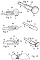
- the coupling element 22 shown on a larger scale in FIGS. 2 and 3 has one sleeve-shaped section 26 and an integrally connected therewith, the coupling end 18 of the coupling arrangement 17 representing flange section 27, which with a concave contact surface 23 is provided.
- the coupling element 22 is with his sleeve-shaped section 26 on the end remote from the transducer 13 Coupling rod 19 plugged in and firmly connected to the coupling rod, for example crimped, welded, soldered or glued.
- FIGS. 4 and 5 show a coupling element 29 which is different from the coupling element 22 only differs in that a to a sleeve-shaped section 30 Coupling end forming spherical head 31 connects.
- the head 31 has a larger one Diameter than section 30 and has convexly curved contact surface 32.
- FIGS. 6 and 7 show a coupling element which is plugged onto the free end of the coupling rod 19 34 with a substantially constant outer diameter and hemispherical Coupling end 35.
- the coupling element 37 illustrated in FIGS. 8, 9 and 10 is similar to the coupling element 22 of Figures 2 and 3. However, it also has a flexible intermediate member in the form of a constriction 38 at the transition point between the sleeve-shaped Section 26 and the flange section 27. Depending on the individual case for the coupling element selected material and the dimensioning of the constriction 38 can thereby the contact surface 23 automatically optimal in spatial angle to the coupling point 16 set, or the coupling element can be customized intraoperatively by the surgeon are optimally plastically deformed.
- the 11 has a coupling element 40 similar to that in the case of the Coupling elements of Figures 2 and 3 with a relatively large area flange portion 41 concave contact surface 23.
- the concave contact surface 23 is complementary convexly curved surface 42 of a thin coupling plate 43 opposite, which in example shown is firmly connected to the surface of the anvil body.
- the coupling plate 43 can be anatomically adapted if necessary. Between surfaces 23 and 42 there is preferably a liquid film 44.
- the coupling element 40 with the coupling rod 19 is blunt connected. Instead, the free coupling rod end can also go from one to the Flange section 41 adjoining sleeve-shaped section according to the figures 5, 7 and 9 are included.
- the contact surface can also be provided by a pivot element according to FIGS. 12 to 14 can be achieved.
- a coupling element 46 is provided, in which the the flange section 27 forming the contact surface 23 connects a ball seat 47.
- a ball head 48 engages in the ball receptacle 47, the part of one with the coupling rod 19 is firmly connected ball joint part 49. That from the ball holder 47 and the Ball joint part 49 existing ball joint 50 not only allows adjustment of the Solid angle of the contact surface 23 with respect to the longitudinal axis of the coupling rod 19, but also a rotation of the coupling rod 19 relative to the Coupling element 46.
- the ball joint part which is firmly connected to the coupling rod 19 as a ball receptacle can be formed, which cooperates with a ball head, the part of Coupling element is.
- a separate intermediate part between the coupling rod and the coupling element can be dispensed with by the Ball head or the ball holder directly on the coupling rod is molded.
- Figures 15 to 18 show an embodiment in which between the coupling rod 19 and a coupling element 52 a flexible intermediate member 53 in the form of a separate one Component is inserted to adjust the solid angle of the contact surface 23 can.
- the coupling element 52 has a relatively large-area flange section 54 a nozzle 55, that of the surface opposite the contact surface 23 of the coupling element 52 protrudes.
- the free end of the connector 55 is slightly crowned and snaps into a complementary recess 56 at one end of the intermediate member 53. In the other end of the intermediate link 53 is correspondingly connected to the coupling rod 19 connected.
- a coil spring 60 is provided, the one Flange section 61 of the coupling element connects to the coupling rod 19.
- the ends the coil spring 60 are at least non-positive with spring supports 63 and 64 the coupling rod 19 or the flange portion 61 connected.
- the spring 60 can optionally be made of a metal alloy with memory effect, in particular nitinol, be made. Such a metal alloy can also be characterized by so-called Characterize "superelasticity", that is, the transmitted force remains as if from the Stress-strain diagram of FIG. 22 emerges, in a certain range too approximately the same for different travel ranges.
- FIGS. 23 to 28 Further possible spring elements are shown in FIGS. 23 to 28.
- a coupling element 71 is provided with a cylindrical section 72, the contact surface between which 23 forming flange portion 73 and a sleeve-shaped portion 74 inserted is.
- a series of 90 ° in the circumferential direction staggered notches 75 are provided, whereby the cylindrical portion 72nd Spring properties are conferred.
- the coupling element 81 illustrated in FIGS. 29 and 30 has a sleeve-shaped one Section 82, which over a slim to the section 82 concentric Shaft 83 is connected to a flat adhesive element 84.
- the adhesive element 84 has an openwork structure with an outer ring 85 and a plurality of spokes 86.
- the coupling element 88 of the exemplary embodiment in FIGS. 31 and 32 has a perforated concave adhesive element 89 is provided.
- the adhesive element 89 is via a shaft 90 with a sleeve-shaped that can be pushed onto the coupling rod Section 91 connected, which is laterally attached to the shaft 90.
- To the adhesive element 89 in turn include an outer ring 92 and a plurality of spokes 93. Die Outer rings 85, 92 cannot be used for better anatomical adjustment also shown broken (slotted).
- an adhesion element 96 has a plurality of protruding arms 97.
- the free ends 98 the arms 97 together form the contact surface.
- the coupling arrangement described can basically be made of any biocompatible Materials, especially metals, metal alloys and / or plastics exist.
- the main metallic materials used are titanium, gold, silver, niobium, tantalum, Platinum, platinum-iridium, or alloys of these metals, implant steel, NiTi (Nitinol) or other biocompatible memory metal.
- plastics It can mainly be silicone, polyurethane, PTFE, FEP, polycarbonate and the like act. This wide selection of plastics in particular is appropriate constrict when special material properties, such as plastic deformability individual adaptation to the target ossicle are required.
- the Total mass of the coupling arrangement is preferably below the mass of the anvil, which averages 25 mg.
- the lowest possible weight of the Coupling arrangement also leads to the reduction of inertial forces Acceleration due to external influences such as shock, vibration and the like.
Landscapes
- Health & Medical Sciences (AREA)
- General Health & Medical Sciences (AREA)
- Otolaryngology (AREA)
- Neurosurgery (AREA)
- Physics & Mathematics (AREA)
- Engineering & Computer Science (AREA)
- Acoustics & Sound (AREA)
- Signal Processing (AREA)
- Prostheses (AREA)
- Coupling Device And Connection With Printed Circuit (AREA)
Applications Claiming Priority (2)
| Application Number | Priority Date | Filing Date | Title |
|---|---|---|---|
| DE19923403A DE19923403C2 (de) | 1999-05-21 | 1999-05-21 | Vorrichtung zum mechanischen Ankoppeln eines in einer Mastoidhöhle implantierbaren elektromechanischen Hörgerätewandlers |
| DE19923403 | 1999-05-21 |
Publications (3)
| Publication Number | Publication Date |
|---|---|
| EP1054573A2 true EP1054573A2 (fr) | 2000-11-22 |
| EP1054573A3 EP1054573A3 (fr) | 2006-01-04 |
| EP1054573B1 EP1054573B1 (fr) | 2007-02-28 |
Family
ID=7908779
Family Applications (1)
| Application Number | Title | Priority Date | Filing Date |
|---|---|---|---|
| EP00105203A Expired - Lifetime EP1054573B1 (fr) | 1999-05-21 | 2000-03-13 | Dispositif pour le couplage mécanique d'un transducteur électromécanique de prothèse auditive implantable dans une cavité dans la mastoidite |
Country Status (5)
| Country | Link |
|---|---|
| US (1) | US6398717B1 (fr) |
| EP (1) | EP1054573B1 (fr) |
| AT (1) | ATE355720T1 (fr) |
| DE (2) | DE19923403C2 (fr) |
| DK (1) | DK1054573T3 (fr) |
Cited By (5)
| Publication number | Priority date | Publication date | Assignee | Title |
|---|---|---|---|---|
| EP1184009A1 (fr) * | 2000-08-24 | 2002-03-06 | Heinz Kurz GmbH Medizintechnik | Dispositif de connexion à l'étrier d'osselets de l'ouie |
| EP1438931A1 (fr) * | 2003-01-17 | 2004-07-21 | Heinz Kurz GmbH Medizintechnik | Prothèse d'osselets flexible |
| US7250059B2 (en) * | 2004-09-14 | 2007-07-31 | Clarity Corporation | Myringopexy type titanium prosthesis |
| CN103460720A (zh) * | 2011-03-23 | 2013-12-18 | 维布兰特美迪医疗电子听觉技术有限公司 | 用于可植入换能器中的振动激励的线传输 |
| EP3427694A1 (fr) * | 2017-07-13 | 2019-01-16 | Heinz Kurz GmbH | Plaque supérieure à autoserrage pour une prothèse d'osselet |
Families Citing this family (48)
| Publication number | Priority date | Publication date | Assignee | Title |
|---|---|---|---|---|
| EP1224840A2 (fr) * | 2000-12-29 | 2002-07-24 | Phonak Ag | Appareil de correction auditive implante dans l'oreille |
| US20030229262A1 (en) * | 2001-11-20 | 2003-12-11 | Easter James Roy | Apparatus and method for ossicular fixation of implantable hearing aid actuator |
| US7278963B2 (en) | 2003-01-27 | 2007-10-09 | Otologics, Llc | Implantable hearing aid transducer with advanceable actuator to facilitate coupling with the auditory system |
| US20030163021A1 (en) * | 2002-02-26 | 2003-08-28 | Miller Douglas Alan | Method and system for external assessment of hearing aids that include implanted actuators |
| DE10212726A1 (de) * | 2002-03-21 | 2003-10-02 | Armin Bernhard | Schallaufnehmer für ein implantierbares Hörgerät |
| US7751580B2 (en) | 2002-09-10 | 2010-07-06 | Auditory Licensing Company, Llc | Open ear hearing aid system |
| US7421086B2 (en) | 2002-09-10 | 2008-09-02 | Vivatone Hearing Systems, Llc | Hearing aid system |
| WO2004067061A2 (fr) * | 2003-01-27 | 2004-08-12 | Otologics Llc | Appareil permettant le raccordement de dispositifs implantables au systeme auditif |
| US6945999B2 (en) * | 2003-01-27 | 2005-09-20 | Otologics Llc | Implantable hearing aid transducer with actuator interface |
| US7273447B2 (en) * | 2004-04-09 | 2007-09-25 | Otologics, Llc | Implantable hearing aid transducer retention apparatus |
| DE10331644B3 (de) * | 2003-07-08 | 2005-01-20 | Technische Universität Dresden | Gehörknöchelchenprothese |
| US7494477B2 (en) | 2003-09-02 | 2009-02-24 | Pulsecath B.V. | Catheter pump, catheter and fittings therefore and methods of using a catheter pump |
| US7137946B2 (en) * | 2003-12-11 | 2006-11-21 | Otologics Llc | Electrophysiological measurement method and system for positioning an implantable, hearing instrument transducer |
| US7186211B2 (en) | 2004-04-09 | 2007-03-06 | Otologics, Llc | Transducer to actuator interface |
| US7153257B2 (en) * | 2004-04-09 | 2006-12-26 | Otologics, Llc | Implantable hearing aid transducer system |
| EP1792519A4 (fr) * | 2004-09-10 | 2010-09-15 | Otologics Llc | Support d'implantation osseuse reglable |
| CA2588810A1 (fr) * | 2004-11-30 | 2006-06-08 | Cochlear Acoustics Ltd | Actionneur implantable pour des applications d'aide auditive |
| GB0500616D0 (en) * | 2005-01-13 | 2005-02-23 | Univ Dundee | Hearing implant |
| US7582052B2 (en) * | 2005-04-27 | 2009-09-01 | Otologics, Llc | Implantable hearing aid actuator positioning |
| WO2007011846A2 (fr) * | 2005-07-18 | 2007-01-25 | Soundquest, Inc. | Dispositif auditif integre dans l'oreille et ses procedes d'utilisation |
| US20070127757A2 (en) * | 2005-07-18 | 2007-06-07 | Soundquest, Inc. | Behind-The-Ear-Auditory Device |
| US20070142697A1 (en) * | 2005-12-16 | 2007-06-21 | Robert Edwin Schneider | Apparatus for connection of implantable devices to the auditory system |
| WO2007147071A2 (fr) * | 2006-06-14 | 2007-12-21 | Otologics, Llc | accouplement de compression d'un actionneur d'aide auditive implantable sur un composant auditif |
| US7792587B2 (en) * | 2006-09-12 | 2010-09-07 | Med-El Elektromedizinische Geraete Gmbh | Middle ear fixation structure |
| KR100847673B1 (ko) | 2006-10-23 | 2008-07-23 | 주성대학산학협력단 | 골도 진동자에 사용되는 에어-쿠션형 매스토이드 및매스토이드의 음향 진폭 및 임피던스 조절 방법 |
| GB0704125D0 (en) * | 2007-03-03 | 2007-04-11 | Univ Dundee | Ossicular replacement prosthesis |
| GB2449114A (en) | 2007-05-11 | 2008-11-12 | Sentient Medical Ltd | Middle ear implant with piezoelectric actuator acting on stapes footplate |
| US7722525B2 (en) * | 2007-05-24 | 2010-05-25 | Otologics, Llc | Lateral coupling of an implantable hearing aid actuator to an auditory component |
| US10645502B2 (en) * | 2007-11-08 | 2020-05-05 | Cochlear Limited | Spanning connector for implantable hearing instrument |
| DE102008015115A1 (de) * | 2008-03-20 | 2009-10-01 | Heinz Kurz Gmbh Medizintechnik | Gehörknöchelchenprothese mit variablen Ankopplungsflächen |
| US20090306458A1 (en) * | 2008-03-31 | 2009-12-10 | Cochlear Limited | Direct acoustic cochlear stimulator for round window access |
| US8262729B2 (en) * | 2008-07-08 | 2012-09-11 | Enteroptyx | Dynamic ossicular prosthesis |
| USD661809S1 (en) * | 2010-01-13 | 2012-06-12 | Widex A/S | Acoustic coupler for a hearing aid |
| AU2011202074A1 (en) * | 2010-01-21 | 2011-08-04 | Med-El Elektromedizinische Geraete Gmbh | Incus replacement partial ossicular replacement prosthesis |
| US20130062535A1 (en) * | 2010-05-31 | 2013-03-14 | Megagen Implant Co. Ltd. | Surface-processing device for a dental implant |
| US9155887B2 (en) | 2010-10-19 | 2015-10-13 | Cochlear Limited | Relay interface for connecting an implanted medical device to an external electronics device |
| KR101223693B1 (ko) * | 2011-06-16 | 2013-01-21 | 경북대학교 산학협력단 | 구동력이 우수한 3코일 타입의 정원창 구동 진동체 |
| US9119010B2 (en) * | 2011-12-09 | 2015-08-25 | Sophono, Inc. | Implantable sound transmission device for magnetic hearing aid, and corresponding systems, devices and components |
| WO2014004425A1 (fr) * | 2012-06-25 | 2014-01-03 | Vibrant Med-El Hearing Technology Gmbh | Précharge optimale pour transducteurs à masse flottante |
| US10362417B2 (en) | 2012-09-28 | 2019-07-23 | Cochlear Limited | Adjustable fixation device having reduced infection |
| WO2015077786A1 (fr) * | 2013-11-25 | 2015-05-28 | Massachusetts Eye & Ear Infirmary | Capteurs piézoélectriques pour prothèses auditives |
| US10348891B2 (en) | 2015-09-06 | 2019-07-09 | Deborah M. Manchester | System for real time, remote access to and adjustment of patient hearing aid with patient in normal life environment |
| FR3046323B1 (fr) * | 2015-12-24 | 2018-02-02 | Universite D'aix Marseille | Microphone implantable pour une prothese d’oreille implantable |
| DE202016105874U1 (de) * | 2016-10-19 | 2016-11-04 | Heinz Kurz Gmbh Medizintechnik | Gehörknöchelchenprothese mit faltbarer Kopfplatte |
| TR201817199A2 (tr) * | 2018-11-14 | 2019-03-21 | Secaattin Guelsen | Bi̇r i̇şi̇tme protezi̇ i̇le sabi̇tleyi̇ci̇ aparat ve bu aparatin uygulama yöntemi̇ |
| CN113058156B (zh) * | 2020-05-26 | 2021-12-07 | 复旦大学 | 一种人工耳蜗的植入装置 |
| DE102021107955A1 (de) * | 2021-03-30 | 2022-10-06 | Med-El Elektromedizinische Geräte GmbH | Gehörknöchelchenprothese |
| RU2766413C1 (ru) * | 2021-04-23 | 2022-03-15 | Общество с ограниченной ответственностью "КОНМЕТ" | Имплантат в качестве протеза слуховых косточек для замещения поврежденных частей среднего уха |
Family Cites Families (21)
| Publication number | Priority date | Publication date | Assignee | Title |
|---|---|---|---|---|
| US3712962A (en) | 1971-04-05 | 1973-01-23 | J Epley | Implantable piezoelectric hearing aid |
| GB1440724A (en) | 1972-07-18 | 1976-06-23 | Fredrickson J M | Implantable electromagnetic hearing aid |
| US3882285A (en) | 1973-10-09 | 1975-05-06 | Vicon Instr Company | Implantable hearing aid and method of improving hearing |
| US4850962A (en) | 1984-12-04 | 1989-07-25 | Medical Devices Group, Inc. | Implantable hearing aid and method of improving hearing |
| US5015225A (en) | 1985-05-22 | 1991-05-14 | Xomed, Inc. | Implantable electromagnetic middle-ear bone-conduction hearing aid device |
| US5015224A (en) | 1988-10-17 | 1991-05-14 | Maniglia Anthony J | Partially implantable hearing aid device |
| US5061280A (en) | 1989-04-04 | 1991-10-29 | Microtek Medical, Inc. | Ossicular prosthesis |
| KR100229086B1 (ko) * | 1990-11-07 | 1999-11-01 | 빈센트 블루비너지 | 청각 장치를 위한 접촉 변환기 조립체 |
| DE4104358A1 (de) | 1991-02-13 | 1992-08-20 | Implex Gmbh | Implantierbares hoergeraet zur anregung des innenohres |
| DE4104359A1 (de) | 1991-02-13 | 1992-08-20 | Implex Gmbh | Ladesystem fuer implantierbare hoerhilfen und tinnitus-maskierer |
| US5554096A (en) | 1993-07-01 | 1996-09-10 | Symphonix | Implantable electromagnetic hearing transducer |
| US5624376A (en) | 1993-07-01 | 1997-04-29 | Symphonix Devices, Inc. | Implantable and external hearing systems having a floating mass transducer |
| DE19618964C2 (de) | 1996-05-10 | 1999-12-16 | Implex Hear Tech Ag | Implantierbares Positionier- und Fixiersystem für aktorische und sensorische Implantate |
| US5707338A (en) | 1996-08-07 | 1998-01-13 | St. Croix Medical, Inc. | Stapes vibrator |
| US6005955A (en) | 1996-08-07 | 1999-12-21 | St. Croix Medical, Inc. | Middle ear transducer |
| US5836863A (en) | 1996-08-07 | 1998-11-17 | St. Croix Medical, Inc. | Hearing aid transducer support |
| US5762583A (en) | 1996-08-07 | 1998-06-09 | St. Croix Medical, Inc. | Piezoelectric film transducer |
| US5997466A (en) | 1996-08-07 | 1999-12-07 | St. Croix Medical, Inc. | Implantable hearing system having multiple transducers |
| DE19738587C1 (de) * | 1997-09-03 | 1999-05-27 | Implex Gmbh | Anordnung zum Einstellen und Fixieren der Relativlage zweier Elemente eines aktiven oder passiven Hör-Implantats |
| DE19745331A1 (de) * | 1997-10-14 | 1999-04-15 | Schumann Klaus | Elektronisches Hörgerät |
| EP0936840A1 (fr) * | 1998-02-16 | 1999-08-18 | Daniel F. àWengen | Prothèse auditive implantable |
-
1999
- 1999-05-21 DE DE19923403A patent/DE19923403C2/de not_active Expired - Fee Related
-
2000
- 2000-03-13 EP EP00105203A patent/EP1054573B1/fr not_active Expired - Lifetime
- 2000-03-13 DE DE50014102T patent/DE50014102D1/de not_active Expired - Lifetime
- 2000-03-13 AT AT00105203T patent/ATE355720T1/de not_active IP Right Cessation
- 2000-03-13 DK DK00105203T patent/DK1054573T3/da active
- 2000-05-22 US US09/576,009 patent/US6398717B1/en not_active Expired - Lifetime
Cited By (7)
| Publication number | Priority date | Publication date | Assignee | Title |
|---|---|---|---|---|
| EP1184009A1 (fr) * | 2000-08-24 | 2002-03-06 | Heinz Kurz GmbH Medizintechnik | Dispositif de connexion à l'étrier d'osselets de l'ouie |
| US6579317B2 (en) | 2000-08-24 | 2003-06-17 | Heinz Kurz Gmbh Medizintechnik | Arrangement for coupling hearing implant |
| EP1438931A1 (fr) * | 2003-01-17 | 2004-07-21 | Heinz Kurz GmbH Medizintechnik | Prothèse d'osselets flexible |
| US7250059B2 (en) * | 2004-09-14 | 2007-07-31 | Clarity Corporation | Myringopexy type titanium prosthesis |
| US7658764B2 (en) | 2004-09-14 | 2010-02-09 | Clarity Corporation | Myringopexy type titanium prosthesis |
| CN103460720A (zh) * | 2011-03-23 | 2013-12-18 | 维布兰特美迪医疗电子听觉技术有限公司 | 用于可植入换能器中的振动激励的线传输 |
| EP3427694A1 (fr) * | 2017-07-13 | 2019-01-16 | Heinz Kurz GmbH | Plaque supérieure à autoserrage pour une prothèse d'osselet |
Also Published As
| Publication number | Publication date |
|---|---|
| EP1054573B1 (fr) | 2007-02-28 |
| ATE355720T1 (de) | 2006-03-15 |
| DE19923403C2 (de) | 2002-11-14 |
| DE50014102D1 (de) | 2007-04-12 |
| US6398717B1 (en) | 2002-06-04 |
| DE19923403A1 (de) | 2000-12-07 |
| DK1054573T3 (da) | 2007-06-11 |
| EP1054573A3 (fr) | 2006-01-04 |
Similar Documents
| Publication | Publication Date | Title |
|---|---|---|
| EP1054573B1 (fr) | Dispositif pour le couplage mécanique d'un transducteur électromécanique de prothèse auditive implantable dans une cavité dans la mastoidite | |
| EP1073313B1 (fr) | Dispositif pour le couplage mécanique d'un vibreur à une place de couplage de la chaîne ossiculaire | |
| DE19948375B4 (de) | Anordnung zum mechanischen Ankoppeln eines Treibers an eine Ankoppelstelle der Ossikelkette | |
| DE19882589B3 (de) | Wandler mit piezoelektrischem Film | |
| EP1179969B1 (fr) | Système auditif au moins partiellement implantable | |
| EP1067820B1 (fr) | Dispositif pour le couplage mécanique d'un vibreur à un place de couplage du chaîne ossicullair | |
| EP0499940B1 (fr) | Transducteur électromécanique pour appareils de correction auditive implantables | |
| EP1173044B1 (fr) | Système implantable de réhabilitation d'un trouble auditif | |
| DE3780245T2 (de) | Implantierbare hoerhilfe. | |
| DE10047388C1 (de) | Mindestens teilweise implantierbares Hörsystem | |
| EP1246503B1 (fr) | Système auditif entièrement implantable | |
| EP1191815B1 (fr) | Système auditif au moins partiellement implantable avec stimulation mécanique d'un espace lymphatique de l'oreille interne | |
| DE69121725T2 (de) | Kontaktübertrager für hörgerät | |
| EP1145734B1 (fr) | Système au moins partiellement implantable de réhabilitation d'un trouble auditif | |
| EP1094687B1 (fr) | Dispositif pour le couplage mécanique d'un vibreur à un place de couplage du chaîne ossicullair | |
| EP1181950B1 (fr) | Système auditif implantable comportant des moyens de mesure de la qualité d'accouplement | |
| EP0984663B1 (fr) | Dispositif transducteur pour prothèses auditives partiellement ou totalment implantées | |
| EP0831673B1 (fr) | Microphone implantable | |
| EP0901779A2 (fr) | Dispositif permettant de régler et fixer la position relative de deux élémentsd'une prothèse auditive active ou passive | |
| EP1439737B1 (fr) | Transducteur électromécanique implantable | |
| CN108886664A (zh) | 中耳联接器的预加载反馈 | |
| DE102009051057B4 (de) | Implantierbarer Sensor-Aktor-Wandlerbaustein für die apparative Hörrehabilitation im Mittelohr | |
| DE102004038078A1 (de) | Implantierbarer Hörgeräteteil | |
| DE102007059748A1 (de) | Positionierungsvorrichtung für aktive Innenohrimplantate |
Legal Events
| Date | Code | Title | Description |
|---|---|---|---|
| PUAI | Public reference made under article 153(3) epc to a published international application that has entered the european phase |
Free format text: ORIGINAL CODE: 0009012 |
|
| AK | Designated contracting states |
Kind code of ref document: A2 Designated state(s): AT BE CH CY DE DK ES FI FR GB GR IE IT LI LU MC NL PT SE |
|
| AX | Request for extension of the european patent |
Free format text: AL;LT;LV;MK;RO;SI |
|
| RAP1 | Party data changed (applicant data changed or rights of an application transferred) |
Owner name: PHONAK AG |
|
| PUAL | Search report despatched |
Free format text: ORIGINAL CODE: 0009013 |
|
| AK | Designated contracting states |
Kind code of ref document: A3 Designated state(s): AT BE CH CY DE DK ES FI FR GB GR IE IT LI LU MC NL PT SE |
|
| AX | Request for extension of the european patent |
Extension state: AL LT LV MK RO SI |
|
| RIC1 | Information provided on ipc code assigned before grant |
Ipc: H04R 25/00 20060101AFI20000905BHEP Ipc: A61F 2/18 20060101ALI20051115BHEP |
|
| 17P | Request for examination filed |
Effective date: 20060601 |
|
| AKX | Designation fees paid |
Designated state(s): AT BE CH CY DE DK ES FI FR GB GR IE IT LI LU MC NL PT SE |
|
| GRAC | Information related to communication of intention to grant a patent modified |
Free format text: ORIGINAL CODE: EPIDOSCIGR1 |
|
| GRAP | Despatch of communication of intention to grant a patent |
Free format text: ORIGINAL CODE: EPIDOSNIGR1 |
|
| GRAS | Grant fee paid |
Free format text: ORIGINAL CODE: EPIDOSNIGR3 |
|
| GRAA | (expected) grant |
Free format text: ORIGINAL CODE: 0009210 |
|
| AK | Designated contracting states |
Kind code of ref document: B1 Designated state(s): AT BE CH CY DE DK ES FI FR GB GR IE IT LI LU MC NL PT SE |
|
| PG25 | Lapsed in a contracting state [announced via postgrant information from national office to epo] |
Ref country code: FI Free format text: LAPSE BECAUSE OF FAILURE TO SUBMIT A TRANSLATION OF THE DESCRIPTION OR TO PAY THE FEE WITHIN THE PRESCRIBED TIME-LIMIT Effective date: 20070228 Ref country code: IE Free format text: LAPSE BECAUSE OF FAILURE TO SUBMIT A TRANSLATION OF THE DESCRIPTION OR TO PAY THE FEE WITHIN THE PRESCRIBED TIME-LIMIT Effective date: 20070228 Ref country code: NL Free format text: LAPSE BECAUSE OF FAILURE TO SUBMIT A TRANSLATION OF THE DESCRIPTION OR TO PAY THE FEE WITHIN THE PRESCRIBED TIME-LIMIT Effective date: 20070228 |
|
| REG | Reference to a national code |
Ref country code: GB Ref legal event code: FG4D Free format text: NOT ENGLISH |
|
| REG | Reference to a national code |
Ref country code: CH Ref legal event code: EP Ref country code: CH Ref legal event code: NV Representative=s name: TROESCH SCHEIDEGGER WERNER AG |
|
| REF | Corresponds to: |
Ref document number: 50014102 Country of ref document: DE Date of ref document: 20070412 Kind code of ref document: P |
|
| REG | Reference to a national code |
Ref country code: IE Ref legal event code: FG4D Free format text: LANGUAGE OF EP DOCUMENT: GERMAN |
|
| PG25 | Lapsed in a contracting state [announced via postgrant information from national office to epo] |
Ref country code: SE Free format text: LAPSE BECAUSE OF FAILURE TO SUBMIT A TRANSLATION OF THE DESCRIPTION OR TO PAY THE FEE WITHIN THE PRESCRIBED TIME-LIMIT Effective date: 20070531 |
|
| PG25 | Lapsed in a contracting state [announced via postgrant information from national office to epo] |
Ref country code: ES Free format text: LAPSE BECAUSE OF FAILURE TO SUBMIT A TRANSLATION OF THE DESCRIPTION OR TO PAY THE FEE WITHIN THE PRESCRIBED TIME-LIMIT Effective date: 20070608 |
|
| GBT | Gb: translation of ep patent filed (gb section 77(6)(a)/1977) |
Effective date: 20070530 |
|
| PG25 | Lapsed in a contracting state [announced via postgrant information from national office to epo] |
Ref country code: PT Free format text: LAPSE BECAUSE OF FAILURE TO SUBMIT A TRANSLATION OF THE DESCRIPTION OR TO PAY THE FEE WITHIN THE PRESCRIBED TIME-LIMIT Effective date: 20070730 |
|
| NLV1 | Nl: lapsed or annulled due to failure to fulfill the requirements of art. 29p and 29m of the patents act | ||
| REG | Reference to a national code |
Ref country code: IE Ref legal event code: FD4D |
|
| EN | Fr: translation not filed | ||
| BERE | Be: lapsed |
Owner name: PHONAK A.G. Effective date: 20070331 |
|
| PG25 | Lapsed in a contracting state [announced via postgrant information from national office to epo] |
Ref country code: BE Free format text: LAPSE BECAUSE OF NON-PAYMENT OF DUE FEES Effective date: 20070331 |
|
| PLBE | No opposition filed within time limit |
Free format text: ORIGINAL CODE: 0009261 |
|
| STAA | Information on the status of an ep patent application or granted ep patent |
Free format text: STATUS: NO OPPOSITION FILED WITHIN TIME LIMIT |
|
| PG25 | Lapsed in a contracting state [announced via postgrant information from national office to epo] |
Ref country code: MC Free format text: LAPSE BECAUSE OF NON-PAYMENT OF DUE FEES Effective date: 20070331 |
|
| 26N | No opposition filed |
Effective date: 20071129 |
|
| PG25 | Lapsed in a contracting state [announced via postgrant information from national office to epo] |
Ref country code: GR Free format text: LAPSE BECAUSE OF FAILURE TO SUBMIT A TRANSLATION OF THE DESCRIPTION OR TO PAY THE FEE WITHIN THE PRESCRIBED TIME-LIMIT Effective date: 20070529 Ref country code: IT Free format text: LAPSE BECAUSE OF FAILURE TO SUBMIT A TRANSLATION OF THE DESCRIPTION OR TO PAY THE FEE WITHIN THE PRESCRIBED TIME-LIMIT Effective date: 20070228 Ref country code: FR Free format text: LAPSE BECAUSE OF FAILURE TO SUBMIT A TRANSLATION OF THE DESCRIPTION OR TO PAY THE FEE WITHIN THE PRESCRIBED TIME-LIMIT Effective date: 20071019 |
|
| PG25 | Lapsed in a contracting state [announced via postgrant information from national office to epo] |
Ref country code: AT Free format text: LAPSE BECAUSE OF NON-PAYMENT OF DUE FEES Effective date: 20070313 |
|
| PG25 | Lapsed in a contracting state [announced via postgrant information from national office to epo] |
Ref country code: FR Free format text: LAPSE BECAUSE OF FAILURE TO SUBMIT A TRANSLATION OF THE DESCRIPTION OR TO PAY THE FEE WITHIN THE PRESCRIBED TIME-LIMIT Effective date: 20070228 |
|
| PG25 | Lapsed in a contracting state [announced via postgrant information from national office to epo] |
Ref country code: CY Free format text: LAPSE BECAUSE OF FAILURE TO SUBMIT A TRANSLATION OF THE DESCRIPTION OR TO PAY THE FEE WITHIN THE PRESCRIBED TIME-LIMIT Effective date: 20070228 |
|
| PG25 | Lapsed in a contracting state [announced via postgrant information from national office to epo] |
Ref country code: LU Free format text: LAPSE BECAUSE OF NON-PAYMENT OF DUE FEES Effective date: 20070313 |
|
| PGFP | Annual fee paid to national office [announced via postgrant information from national office to epo] |
Ref country code: DK Payment date: 20110303 Year of fee payment: 12 |
|
| PGFP | Annual fee paid to national office [announced via postgrant information from national office to epo] |
Ref country code: CH Payment date: 20110303 Year of fee payment: 12 |
|
| PGFP | Annual fee paid to national office [announced via postgrant information from national office to epo] |
Ref country code: GB Payment date: 20110302 Year of fee payment: 12 |
|
| REG | Reference to a national code |
Ref country code: CH Ref legal event code: PL |
|
| REG | Reference to a national code |
Ref country code: DK Ref legal event code: EBP |
|
| GBPC | Gb: european patent ceased through non-payment of renewal fee |
Effective date: 20120313 |
|
| PG25 | Lapsed in a contracting state [announced via postgrant information from national office to epo] |
Ref country code: CH Free format text: LAPSE BECAUSE OF NON-PAYMENT OF DUE FEES Effective date: 20120331 Ref country code: LI Free format text: LAPSE BECAUSE OF NON-PAYMENT OF DUE FEES Effective date: 20120331 Ref country code: GB Free format text: LAPSE BECAUSE OF NON-PAYMENT OF DUE FEES Effective date: 20120313 |
|
| PG25 | Lapsed in a contracting state [announced via postgrant information from national office to epo] |
Ref country code: DK Free format text: LAPSE BECAUSE OF NON-PAYMENT OF DUE FEES Effective date: 20120331 |
|
| PGFP | Annual fee paid to national office [announced via postgrant information from national office to epo] |
Ref country code: DE Payment date: 20130331 Year of fee payment: 14 |
|
| REG | Reference to a national code |
Ref country code: DE Ref legal event code: R082 Ref document number: 50014102 Country of ref document: DE Representative=s name: GRUENECKER, KINKELDEY, STOCKMAIR & SCHWANHAEUS, DE |
|
| REG | Reference to a national code |
Ref country code: DE Ref legal event code: R119 Ref document number: 50014102 Country of ref document: DE |
|
| REG | Reference to a national code |
Ref country code: DE Ref legal event code: R119 Ref document number: 50014102 Country of ref document: DE Effective date: 20141001 |
|
| PG25 | Lapsed in a contracting state [announced via postgrant information from national office to epo] |
Ref country code: DE Free format text: LAPSE BECAUSE OF NON-PAYMENT OF DUE FEES Effective date: 20141001 |