EP1054764B1 - Dispositif destine a gaufrer et stratifier des bandes continues - Google Patents
Dispositif destine a gaufrer et stratifier des bandes continues Download PDFInfo
- Publication number
- EP1054764B1 EP1054764B1 EP99905180A EP99905180A EP1054764B1 EP 1054764 B1 EP1054764 B1 EP 1054764B1 EP 99905180 A EP99905180 A EP 99905180A EP 99905180 A EP99905180 A EP 99905180A EP 1054764 B1 EP1054764 B1 EP 1054764B1
- Authority
- EP
- European Patent Office
- Prior art keywords
- embossing
- cylinder
- cylinders
- embossing cylinder
- tips
- Prior art date
- Legal status (The legal status is an assumption and is not a legal conclusion. Google has not performed a legal analysis and makes no representation as to the accuracy of the status listed.)
- Revoked
Links
- 238000004049 embossing Methods 0.000 title claims abstract description 181
- 238000010030 laminating Methods 0.000 title claims abstract description 44
- 239000000463 material Substances 0.000 title claims abstract description 14
- 239000000853 adhesive Substances 0.000 claims abstract description 7
- 230000001070 adhesive effect Effects 0.000 claims abstract description 7
- 230000002093 peripheral effect Effects 0.000 claims description 3
- 238000005304 joining Methods 0.000 description 8
- 238000000034 method Methods 0.000 description 8
- 239000003292 glue Substances 0.000 description 3
- 230000033001 locomotion Effects 0.000 description 3
- 230000005540 biological transmission Effects 0.000 description 2
- 238000006243 chemical reaction Methods 0.000 description 2
- 238000004140 cleaning Methods 0.000 description 2
- 238000004519 manufacturing process Methods 0.000 description 2
- 238000012986 modification Methods 0.000 description 2
- 230000004048 modification Effects 0.000 description 2
- 230000006835 compression Effects 0.000 description 1
- 238000007906 compression Methods 0.000 description 1
- 239000000109 continuous material Substances 0.000 description 1
- 230000001419 dependent effect Effects 0.000 description 1
- 238000010586 diagram Methods 0.000 description 1
- 238000006073 displacement reaction Methods 0.000 description 1
- 238000001035 drying Methods 0.000 description 1
- 230000000694 effects Effects 0.000 description 1
- 238000003780 insertion Methods 0.000 description 1
- 230000037431 insertion Effects 0.000 description 1
- 238000003475 lamination Methods 0.000 description 1
- 230000001105 regulatory effect Effects 0.000 description 1
- 230000003252 repetitive effect Effects 0.000 description 1
- 239000012858 resilient material Substances 0.000 description 1
Images



Classifications
-
- B—PERFORMING OPERATIONS; TRANSPORTING
- B31—MAKING ARTICLES OF PAPER, CARDBOARD OR MATERIAL WORKED IN A MANNER ANALOGOUS TO PAPER; WORKING PAPER, CARDBOARD OR MATERIAL WORKED IN A MANNER ANALOGOUS TO PAPER
- B31F—MECHANICAL WORKING OR DEFORMATION OF PAPER, CARDBOARD OR MATERIAL WORKED IN A MANNER ANALOGOUS TO PAPER
- B31F1/00—Mechanical deformation without removing material, e.g. in combination with laminating
- B31F1/07—Embossing, i.e. producing impressions formed by locally deep-drawing, e.g. using rolls provided with complementary profiles
-
- B—PERFORMING OPERATIONS; TRANSPORTING
- B31—MAKING ARTICLES OF PAPER, CARDBOARD OR MATERIAL WORKED IN A MANNER ANALOGOUS TO PAPER; WORKING PAPER, CARDBOARD OR MATERIAL WORKED IN A MANNER ANALOGOUS TO PAPER
- B31F—MECHANICAL WORKING OR DEFORMATION OF PAPER, CARDBOARD OR MATERIAL WORKED IN A MANNER ANALOGOUS TO PAPER
- B31F2201/00—Mechanical deformation of paper or cardboard without removing material
- B31F2201/07—Embossing
- B31F2201/0758—Characteristics of the embossed product
- B31F2201/0761—Multi-layered
- B31F2201/0764—Multi-layered the layers being nested
-
- B—PERFORMING OPERATIONS; TRANSPORTING
- B31—MAKING ARTICLES OF PAPER, CARDBOARD OR MATERIAL WORKED IN A MANNER ANALOGOUS TO PAPER; WORKING PAPER, CARDBOARD OR MATERIAL WORKED IN A MANNER ANALOGOUS TO PAPER
- B31F—MECHANICAL WORKING OR DEFORMATION OF PAPER, CARDBOARD OR MATERIAL WORKED IN A MANNER ANALOGOUS TO PAPER
- B31F2201/00—Mechanical deformation of paper or cardboard without removing material
- B31F2201/07—Embossing
- B31F2201/0758—Characteristics of the embossed product
- B31F2201/0761—Multi-layered
- B31F2201/0766—Multi-layered the layers being superposed tip to tip
-
- B—PERFORMING OPERATIONS; TRANSPORTING
- B31—MAKING ARTICLES OF PAPER, CARDBOARD OR MATERIAL WORKED IN A MANNER ANALOGOUS TO PAPER; WORKING PAPER, CARDBOARD OR MATERIAL WORKED IN A MANNER ANALOGOUS TO PAPER
- B31F—MECHANICAL WORKING OR DEFORMATION OF PAPER, CARDBOARD OR MATERIAL WORKED IN A MANNER ANALOGOUS TO PAPER
- B31F2201/00—Mechanical deformation of paper or cardboard without removing material
- B31F2201/07—Embossing
- B31F2201/0771—Other aspects of the embossing operations
- B31F2201/0774—Multiple successive embossing operations
-
- B—PERFORMING OPERATIONS; TRANSPORTING
- B31—MAKING ARTICLES OF PAPER, CARDBOARD OR MATERIAL WORKED IN A MANNER ANALOGOUS TO PAPER; WORKING PAPER, CARDBOARD OR MATERIAL WORKED IN A MANNER ANALOGOUS TO PAPER
- B31F—MECHANICAL WORKING OR DEFORMATION OF PAPER, CARDBOARD OR MATERIAL WORKED IN A MANNER ANALOGOUS TO PAPER
- B31F2201/00—Mechanical deformation of paper or cardboard without removing material
- B31F2201/07—Embossing
- B31F2201/0782—Layout of the complete embossing machine, of the embossing line
-
- B—PERFORMING OPERATIONS; TRANSPORTING
- B31—MAKING ARTICLES OF PAPER, CARDBOARD OR MATERIAL WORKED IN A MANNER ANALOGOUS TO PAPER; WORKING PAPER, CARDBOARD OR MATERIAL WORKED IN A MANNER ANALOGOUS TO PAPER
- B31F—MECHANICAL WORKING OR DEFORMATION OF PAPER, CARDBOARD OR MATERIAL WORKED IN A MANNER ANALOGOUS TO PAPER
- B31F2201/00—Mechanical deformation of paper or cardboard without removing material
- B31F2201/07—Embossing
- B31F2201/0784—Auxiliary operations
- B31F2201/0787—Applying adhesive
-
- Y—GENERAL TAGGING OF NEW TECHNOLOGICAL DEVELOPMENTS; GENERAL TAGGING OF CROSS-SECTIONAL TECHNOLOGIES SPANNING OVER SEVERAL SECTIONS OF THE IPC; TECHNICAL SUBJECTS COVERED BY FORMER USPC CROSS-REFERENCE ART COLLECTIONS [XRACs] AND DIGESTS
- Y10—TECHNICAL SUBJECTS COVERED BY FORMER USPC
- Y10T—TECHNICAL SUBJECTS COVERED BY FORMER US CLASSIFICATION
- Y10T156/00—Adhesive bonding and miscellaneous chemical manufacture
- Y10T156/10—Methods of surface bonding and/or assembly therefor
- Y10T156/1002—Methods of surface bonding and/or assembly therefor with permanent bending or reshaping or surface deformation of self sustaining lamina
- Y10T156/1007—Running or continuous length work
- Y10T156/1023—Surface deformation only [e.g., embossing]
-
- Y—GENERAL TAGGING OF NEW TECHNOLOGICAL DEVELOPMENTS; GENERAL TAGGING OF CROSS-SECTIONAL TECHNOLOGIES SPANNING OVER SEVERAL SECTIONS OF THE IPC; TECHNICAL SUBJECTS COVERED BY FORMER USPC CROSS-REFERENCE ART COLLECTIONS [XRACs] AND DIGESTS
- Y10—TECHNICAL SUBJECTS COVERED BY FORMER USPC
- Y10T—TECHNICAL SUBJECTS COVERED BY FORMER US CLASSIFICATION
- Y10T156/00—Adhesive bonding and miscellaneous chemical manufacture
- Y10T156/17—Surface bonding means and/or assemblymeans with work feeding or handling means
- Y10T156/1702—For plural parts or plural areas of single part
- Y10T156/1712—Indefinite or running length work
- Y10T156/1737—Discontinuous, spaced area, and/or patterned pressing
-
- Y—GENERAL TAGGING OF NEW TECHNOLOGICAL DEVELOPMENTS; GENERAL TAGGING OF CROSS-SECTIONAL TECHNOLOGIES SPANNING OVER SEVERAL SECTIONS OF THE IPC; TECHNICAL SUBJECTS COVERED BY FORMER USPC CROSS-REFERENCE ART COLLECTIONS [XRACs] AND DIGESTS
- Y10—TECHNICAL SUBJECTS COVERED BY FORMER USPC
- Y10T—TECHNICAL SUBJECTS COVERED BY FORMER US CLASSIFICATION
- Y10T156/00—Adhesive bonding and miscellaneous chemical manufacture
- Y10T156/17—Surface bonding means and/or assemblymeans with work feeding or handling means
- Y10T156/1702—For plural parts or plural areas of single part
- Y10T156/1712—Indefinite or running length work
- Y10T156/1741—Progressive continuous bonding press [e.g., roll couples]
-
- Y—GENERAL TAGGING OF NEW TECHNOLOGICAL DEVELOPMENTS; GENERAL TAGGING OF CROSS-SECTIONAL TECHNOLOGIES SPANNING OVER SEVERAL SECTIONS OF THE IPC; TECHNICAL SUBJECTS COVERED BY FORMER USPC CROSS-REFERENCE ART COLLECTIONS [XRACs] AND DIGESTS
- Y10—TECHNICAL SUBJECTS COVERED BY FORMER USPC
- Y10T—TECHNICAL SUBJECTS COVERED BY FORMER US CLASSIFICATION
- Y10T156/00—Adhesive bonding and miscellaneous chemical manufacture
- Y10T156/17—Surface bonding means and/or assemblymeans with work feeding or handling means
- Y10T156/1702—For plural parts or plural areas of single part
- Y10T156/1744—Means bringing discrete articles into assembled relationship
Definitions
- the present invention relates to a device for embossing and laminating continuous plies for forming a web material.
- the present invention relates to an embossing and laminating device of the type comprising a pair of embossing cylinders, each co-operating with a respective pressure roll, with a glue applicator for applying an adhesive onto at least one of the embossed plies, and with laminating means which cause joining together of two plies separately embossed between each embossing cylinder and the respective pressure roll.
- two plies are each embossed between an embossing cylinder, provided with projections or tips arranged in a repetitive pattern, and a pressure roll, normally lined with resilient material, such as rubber or the like.
- the two plies are joined together by means of laminating between the two facing embossing cylinders which are phase-synchronized with one another so that, in the laminating nip between the two cylinders, the tips of one cylinder are located opposite the tips of the other one, the distance between the cylinders being such as to cause laminating of the plies between the facing tips.
- an adhesive is applied onto one of the two plies, in the relief zones produced by embossing.
- Nested-type embossing and joining together involves the plies which are separately embossed in a similar manner to that described above being joined together so that the projections of one ply are arranged in between the projections of the other one.
- the two embossing cylinders are not pressed against one another in the nip between them and the two plies are joined together by means of laminating between one of the two embossing cylinders and a joining roller.
- This technique is described in GB-B-1,225,440 and in US-A-3,694,300.
- Italian Utility Model Application No. 21,325B/89 describes a device which allows embossing both of the nested type and embossing of the tip-to-tip type to be performed by modifying as required the arrangement of the components of the device. Basically, in order to change from one type of processing to the other type, it is necessary to modify entirely the arrangement of the embossing cylinders. In fact, according to this known technique, it is suggested basically to convert on each occasion a proper tip-to-tip embossing unit into a proper nested embossing unit. This involves very long operation times in order to pass from one type of embossing system to the other.
- the object of the present invention is to provide an embossing/laminating device which is able to operate in tip-to-tip or nested mode and which allows easy conversion from one type of embossing to the other, reducing to a minimum the operations of adjustment and regulation of the device.
- Yet another object of the present invention consists in providing a configuration which allows the existing embossing/laminating units, of the tip-to-tip type, to be converted in a rapid and economic manner into dual-purpose embossing/laminating units suitable for producing embossed material (comprising several glued plies) using the nested technique and the tip-to-tip technique, alternately.
- a further object of one improved embodiment of the present invention is the provision of an embossing unit in which the embossing cylinders and the pressure rolls are arranged so as to reduce the irregularities in the laminated product due to the flexural deformations of the embossing cylinders.
- an embossing and laminating device of the type comprising: a first and a second embossing cylinder, provided with associated tips or projections, said two embossing cylinders being arranged with parallel axes and arranged adjacent to one another so as to form a nip between them; a pair of pressure rolls, each of which co-operates with one of the embossing cylinders; an adhesive applicator associated with the first embossing cylinder; and a laminating roll arranged downstream of the nip between the embossing cylinders and cooperating with the first embossing cylinder.
- the planes containing the axis of each embossing cylinder and the axis of the corresponding pressure roll are both inclined with respect to the plane containing the axes of the embossing cylinders at an angle different from 0° and 90° and that the angle formed by the plane containing the axis of the first embossing cylinder and the respective pressure roll with the plane containing the axes of the two embossing cylinders and directed towards the side of said nip from which the embossed web material emerges from said nip is greater than 90°.
- said two embossing cylinders should have the same peripheral speeds and that they may be phase-synchronized with each other so as to bring the tips of one embossing cylinder opposite the tips of the other embossing cylinder, or alternatively cause the tips of one embossing cylinder to engage in between the tips of the other embossing cylinder, without necessarily modifying the interaxial distance between the cylinders.
- a greater space for arranging the marrying or laminating roll is created around the first embossing cylinder.
- This allows one to pass from the tip-to-tip configuration to the nested configuration without moving the embossing cylinders away from one another.
- the existing tip-to-tip embossing units may be easily modified so as to vary the mutual position of the axes of the pressure rolls and the embossing cylinders and introduce into the space thus formed a laminating roll, this making the unit suitable for producing also web material embossed and joined using the nested technique.
- the embossing cylinders may have symmetrical tips arrangements or (in particular when the device is operating in the nested configuration) non-symmetrical arrangements.
- the embossing cylinders may also be replaced when the device changes over from the tip-to-tip configuration to the nested configuration, or vice versa.
- the phase-displacement between the tips of an embossing cylinder and the tips of the other cylinder may be obtained with an angular movement or also with a mutual axial movement of the cylinders.
- the other cylinder may be rotated about its axis, or translated parallel to its axis, by an amount such as to cause its tips to engage in between the tips of the other cylinder.
- the two planes containing the axes of the embossing cylinders and the respective pressure rolls are inclined in directions such as to cause deformations which have components coinciding in the plane containing the axes of the two embossing cylinders. This is obtained by arranging the pressure roll associated with the first embossing cylinder in an angular position which is further away from the nip and the pressure roll associated with the second embossing cylinder closer to the nip.
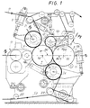
- the device comprises a pair of embossing cylinders 1, 3, each of which is provided with a plurality of tips or projections 1P, 3P (schematically shown in Figs. 2 to 4) arranged in symmetrical patterns on the two cylinders.
- the two cylinders 1, 3 are mechanically joined together so as to rotate in opposed directions, as shown by the arrows f1 and f3, and at the same peripheral speed. This may be obtained with a suitable choice of transmission gears, not shown.
- the embossing cylinder 1 cooperates with a pressure roll 5, while the cylinder 3 cooperates with a pressure roll 7.
- the two pressure rolls 5 and 7 are lined with a layer of resiliently yielding material, for example rubber.
- Each pressure roll 5, 7 is biased against the respective embossing cylinder 1, 3 by an actuator 9, 11.
- the pressure rolls 3 and 5 are not positioned either with their axes on a plane perpendicular to the plane containing the axes of the respective embossing cylinders 1 and 3, nor coplanar with the embossing cylinders.
- the plane P3 containing the axes 1A and 5A of the embossing cylinder 1 and the pressure roll 5 forms an angle of about 30° with the vertical.
- the plane P5 containing the axis 3A of the embossing cylinder 3 and 7A of the pressure roll 7 is also inclined at about 30° with respect to the vertical, but in the opposite direction with respect to the plane P3.
- ⁇ and ⁇ ' indicate the two angles formed by the planes P3 and P5 with the plane P2 containing the axes 1A, 3A of the two embossing cylinders 1, 3.
- the two angles ⁇ and ⁇ ' are in this case supplementary (their sum is equal to 180°) and are obtained by displacing the pressure roll 5 associated with the first embossing cylinder 1 so as to move it away from the nip G, while the pressure roll 7 has been moved towards the nip G.
- the position of the pressure roll 5 makes available a space around the cylinder 1, between the roll 5 and the cylinder 3, for the arrangement of a marrying or laminating roll 13, cooperating with the cylinder 1, for the purposes clarified below.
- the laminating roll 13 is controlled by an actuator 15 so as to assume an active position, shown in continuous lines in Fig. 1, where it is pressed against the surface of the embossing cylinder 1, and a non-active position, shown in broken lines, where it is not in contact with the cylinder 1.
- a flexural stress is generated on the embossing cylinder 1, said stress having a horizontal component (in the plane P2 containing the axes 1A and 3A of the cylinders 1 and 3) which causes a corresponding deformation (camber) in the horizontal plane P2.
- This deformation would cause a high degree of compression of the projections 1P, 3P in the intermediate zone (in the direction of the axis of the cylinders 1, 3) of the laminating nip G, where the deformation of the cylinder 1 is maximum.
- the pressure roll 7 is also displaced with respect to the vertical containing the axis 3A, so that the stress exerted by the pressure roll 7 on the embossing cylinder 3 causes a flexural deformation of the latter in the plane P2 in the same direction as that caused by the pressure roll on the embossing cylinder 1.
- the two axes of the embossing cylinders 1 and 3 are thus deformed substantially by the same amount and in the same plane, such that the cooperating projections of the two cylinders are located substantially at the same distance, i.e. are pressed with the same stress against one another, along the entire longitudinal extension of the laminating nip G, when the embossing/laminating unit is operating in the tip-to-tip condition.
- the embossing cylinder 1 has, associated with it, an adhesive applicator 17 of the type known per se. It comprises, in the example illustrated, two cylinders, the axes of rotation of which are coplanar with the axes 1A, 3A of the two embossing cylinders 1, 3.
- V1 and V3 Two plies of material to be embossed, indicated by V1 and V3, are supplied to the device described hitherto.
- 20 denotes a roll for guiding the ply V3, while 21 and 23 denote two expansion rolls for the plies V1 and V3, respectively.
- the ply V1 is embossed between the embossing cylinder 1 and the pressure roll 5, while the ply V3 is embossed between the embossing cylinder 3 and the pressure roll 7.
- an adhesive C is applied onto the ply V1 by means of the applicator 17 in a manner known per se.
- the two plies V1 and V3 may, at this point, be joined together in two different ways depending on how the two embossing cylinders 1, 3 are phase-synchronized and the path which the plies follow downstream of the nip G between the embossing cylinders 1,3.
- Fig. 2 shows an enlarged detail of the nip G between the two embossing cylinders 1, 3 in the position which they assume when the device is regulated to obtain tip-to-tip embossing.
- the two cylinders 1, 3 are phase-synchronized with each other so that the tips or projections 1P of the cylinder 1 are in phase with the tips 3P of the cylinder 3, namely at the minimum inter-distance point between the two cylinders 1, 3 the tips of one press against the tips of the other one, laminating between them the embossed plies V1 and V3.
- the glue applied onto the ply V1 causes mutual adhesion of the plies.
- Downstream of the nip G the web material formed by the two joined plies V1 and V3 follows the path indicated by Npp. In this condition the laminating roll 13 is kept separated from the embossing cylinder 1.
- Figs. 3 and 4 show the arrangement of the embossing cylinders 1, 3 and the laminating roll 13 in the case of nested embossing.
- the two embossing cylinders 1 and 3 are arranged with the same interaxial distance as the preceding example, but are differently phase-synchronized since the tips 1 P of the embossing cylinder 1 are engaged in between the tips 3P of the embossing cylinder 3.
- the two embossed plies V1 and V3 are not laminated in the nip G between the two embossing cylinders 1, 3, but downstream of the nip G, between the laminating roll 13 (which in this case is pressed against the tips 1P of the cylinder 1) and the embossing cylinder 1, as shown in the schematic enlarged view of Fig. 4. Downstream of the laminating roll 13, the web material obtained from joining together of the plies V1 and V3 follows the path Nn.
- Fig. 5 shows a side view, similar to Fig. 1, of a modified embodiment of the present invention.
- the same numbers indicate parts which are the same or correspond to those of the embodiment according to Figs. 1 to 4.
- the plane P2 is inclined with respect to the horizontal, and the planes P3 and P5 form angles ⁇ and ⁇ ' with the plane P2, which are equal to each other. Both the pressure rolls 5 and 7 have been moved away from the nip G.
- Figs 6 and 7 show an embodiment of the device according to the present invention in which the conversion of the embossing cylinders arrangement to move from one type of embossing to the other or vice versa is particularly simple.
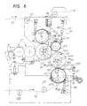
- Fig. 6 shows the configuration for the nested mode while Fig. 7 shows the same device in configuration for the the tip-to-tip mode of operation.
- the device in the configuration of Fig. 6 will firstly be described.
- same parts or parts corresponding to those of Fig. 5 are indicated with the same reference numbers increased by 100.
- the device includes a first embossing cylinder 101 and a second embossing cylinder 103, having rotation axes 101A and 103A arranged on a plane P102 which is inclined with respect to the horizontal.
- the first embossing cylinder 101 cooperates with a first pressure roll 105 and the second embossing cylinder 103 cooperates with a second pressure roll 107, both pressure rolls being lined with a yielding material.
- the two pressure rolls 105 and 107 are arranged above and below the inclined plane P102 respectively, on which the axes 101A and 103A of the embossing cylinders 101, 103 are arranged.
- the axes of pressure rolls 105 and 107 are shown at 105A and 107A, while P103 and P105 indicate respectively the plane including the axis 105A of the pressure roll 105 and the axis 101A of embossing cylinder 101 on the one side and the axis 107A of pressure roll 107 and the axis 103A of the second embossing cylinder 103 on the other.
- the angles formed by the plane P102 with plane P105 and plane P103 respectively are shown at ⁇ and ⁇ ' respectively.
- the first embossing cylinder 101 cooperates also with a laminating roll 113 and with a glue applicator 117. Between the laminator roll 113 and the pressure roll 105 a cleaning brush 116 operates, which has the function of cleaning the surface of the embossing cylinder 101.
- the second embossing cylinder 103 is supported by a pair of sides, only one of which is shown in Fig. 6 and labeled 151.
- Each side 151 is divided into two portions: the first portion 151A is pivoted at 153 to the fixed structure 155 of the device and is provided with an arm 151B upon which a thrust actuator 157 acts.
- the second portion 151C of the side 151 is mounted on portion 151A in such a way as to be removable therefrom and is provided with seats for the bearings for embossing cylinder 103.
- the laminating roll 113 is supported by a pair of small sides 161 pivoted at 163 to the fixed structure 155 of the device. Each small side 161 is combined to a thrust actuator 115 acting upon it, equivalent to actuator 15 of Fig. 5, which pushes the laminating roll 113 against the first embossing cylinder 101.
- a seat 165 is provided for supporting a further pressure roll which can be used in alternative to the pressure roll 107 and to the laminating roll 113 as will be made clear when describing the arrangement shown in Fig. 7.
- the motion between embossing cylinders 101 and 103 is transmitted via a gear train transmission.
- the latter allows, when requested, to modify the angular phase between the two embossing cylinders in order to bring the tips of one cylinder to correspond to the tips of the other (tip-to-tip mode of operation) or to be located in between the tips of the other cylinder alternatively (nested mode of operation).
- the device operates preferably in the nested mode and therefore the tips of the two embossing cylinders 101, 103 are arranged in such a way that they do not correspond to one another so that the two plies V1, V2 are not laminated between the two embossing cylinders 101, 103 which are not in mutual contact.
- the plies are rather laminated between the first embossing cylinder 101 and the laminating roll 113.
- the modification includes the replacement of portions 151C of the sides 151 with different portions 151D which support a modified embossing cylinder 103'.
- embossing cylinder 101 which may be the same as in the arrangement of Fig. 6 or may have been replaced with another having a different embossing pattern.
- the new embossing cylinder 103' cooperates with a pressure roll 107' replacing pressure roll 107 (which remains inactive or may be removed).
- the pressure roll 107' is supported by small sides 171 pivoted near seat 165.
- Each small side 171 is connected to the same thrust actuator 115 which in the arrangement of Fig. 6 acts on the small sides supporting the laminating roll 113. The latter has been removed in order to provide the room necessary for the pressure roll 107'. Therefore, in this arrangement the actuator 115 performs the function of actuator 11 of the device shown in Fig. 5, while in the arrangement of Fig. 6 said function was performed by actuator 111.
- embossing cylinder 103' may be actually different from cylinder 103 (e.g. it may have a different pattern), or it may be the same cylinder 103 arranged in a different position.
- an auxiliary deflecting roll 177 is also provided for deflecting the ply V2, whose path is different from the path followed in the arrangement of Fig. 6.
Landscapes
- Engineering & Computer Science (AREA)
- Mechanical Engineering (AREA)
- Machines For Manufacturing Corrugated Board In Mechanical Paper-Making Processes (AREA)
- Laminated Bodies (AREA)
- Folding Of Thin Sheet-Like Materials, Special Discharging Devices, And Others (AREA)
- Shaping Of Tube Ends By Bending Or Straightening (AREA)
- Extrusion Moulding Of Plastics Or The Like (AREA)
- Manufacturing Of Electric Cables (AREA)
- Paper (AREA)
Claims (15)
- Dispositif de gaufrage et de laminage d'un matériau en bande à plusieurs couches, comprenant: un premier et un second cylindres de gaufrage (1,3; 101,103) munis de pointes (1P,3P ; 101P,103), les deux cylindres de gaufrage étant disposés avec des axes parallèles (1A,3A ; 101A,103A) et adjacents l'un à l'autre de manière à former un étranglement (G) entre eux et tournant à la même vitesse périphérique dans des directions opposées ; une paire de galets de pression (5,7 ; 105,107), chacun d'eux coopérant avec l'un des cylindres de gaufrage ; et un applicateur de colle (17 ; 117) associé au premier cylindre de gaufrage ; et un galet de laminage (13 ; 113) disposé en aval de l'étranglement (G) entre les cylindres de gaufrage (1,3 ; 101,103) et coopérant avec le premier cylindre de gaufrage (1 ; 101) ; et dans lequel les deux cylindres de gaufrage (1,3 ; 101,103) peuvent être synchronisés en phase l'un avec l'autre de manière à amener les pointes (1P ; 101P) de l'un des cylindres de gaufrage (1 ; 101) à l'opposé des pointes (3P ; 103P) de l'autre cylindre de gaufrage (3 ; 103), ou alternativement provoquer l'engagement des pointes (1P ; 101P) de l'un des cylindres de gaufrage (1 ; 101) entre les pointes (3P ; 103P) de l'autre cylindre de gaufrage (3 ; 103).
caractérisé en ce queles plans (P3,P5 ; P103,P105) contenant les axes (1A,3A ; 101A,103A) de chaque cylindre de gaufrage (1,3 ; 101,103) et les axes (5A,7A ; 105A,107A) du galet de pression correspondant (5,7 ; 105,107) sont tous les deux inclinés par rapport aux plans (P2 ; P102) contenant les axes (1A,3A ; 101A,103A) des cylindres de gaufrage selon un angle (α,α') différent de 0° et 90° ; etl'angle (α') formé par le plan (P3 ; P103) contenant les axes (1A ; 101A) du premier cylindre de gaufrage (1 ; 101) et l'axe (5A ; 105A) du galet de pression respectif (5 ; 105) avec le plan (P2 ; P102) contenant les axes (1A,3A ; 101A,103A) des deux cylindres de gaufrage (1,3 ; 101,103), et dirigé vers le côté de l'étranglement à partir duquel le matériau en bande gaufré émerge de la pointe, est supérieur à 90°. - Dispositif tel que revendiqué dans la revendication 1, caractérisé en ce que la distance interaxiale des cylindres de gaufrage reste substantiellement inchangée au cours des changements de configuration où les pointes de l'un des cylindres de gaufrage correspondent avec les pointes de l'autre cylindre de gaufrage jusqu'à la configuration où les pointes de l'un des cylindres de gaufrage s'engagent entre les pointes de l'autre cylindre de gaufrage ou vice-versa.
- Dispositif tel que revendiqué dans la revendication 1 ou 2, caractérisé en ce que les plans (P3,P5) contenant les axes (1A,3) de chaque cylindre de gaufrage (1,3) et les axes du galet de pression correspondant (5A,7A) sont inclinés dans des directions telles qu'elles provoquent sur les deux cylindres de gaufrage (1,3) des déformations par flexion avec des composants coïncidant dans le plan (P2) contenant les axes desdits cylindres de gaufrage.
- Dispositif tel que revendiqué dans la revendication 3, caractéisé en ce que les plans forment des angles supplémentaires (α,α').
- Dispositif tel que revendiqué dans l'une ou plusieurs des revendications précédentes, caractérisé en ce que le galet de laminage (13) peut être amené alternativement de manière à être pressé contre le premier cylindre de gaufrage (1) ou à une distance de celui-ci.
- Dispositif tel que revendiqué dans l'une ou plusieurs des revendications précédentes, caractérisé en ce que les axes (1A,3A) des deux cylindres de gaufrage (1,3) sont situés dans un plan horizontal (P2).
- Dispositif tel que revendiqué dans l'une ou plusieurs des revendications précédentes, caractérisé en ce que les deux galets de pression (5,7) sont disposés l'un au-dessus et l'autre en dessous des cylindres de gaufrage respectifs (1,3).
- Dispositif tel que revendiqué dans l'une ou plusieurs des revendications précédentes, caractérisé en ce que le plan (P3) contenant les axes (1A) du premier cylindre de gaufrage (1) et le galet de pression respectif (5) forment un angle (α') situé entre 95° et 130° et de préférence entre 95° et 120° avec le plan contenant les axes (1A,3A) des cylindres de gaufrage (1,3).
- Dispositif tel que revendiqué dans la revendication 1, caractérisé en ce que les plans (P3,P5) contenant les axes (1A,3A) de chaque cylindre de gaufrage (1,3) et les axes du galet de pression correspondant (5A,7A) forment avec le plan (P2) contenant les axes des cylindres de gaufrage (1,3) des angles (α,α') égaux.
- Dispositif tel que revendiqué dans la revendication 9, caractérisé en ce que le plan (P2) contenant les axes (1A,3A) des cylindres de gaufrage est incliné par rapport à l'horizontal.
- Dispositif tel que revendiqué dans l'une ou plusieurs des revendications précédentes, caractérisé en ce que le second cylindra de gaufrage (103) est supporté par les côtés (151) constitués de deux parties (151A,151C) qui peuvent être séparées pour replacer aisément ledit cylindre de gaufrage.
- Dispositif tel que revendiqué dans la revendication 11, caractérisé en ce que les côtés supportant le second cylindre de gaufrage (103) sont dessinés de telle manière qu'en séparant la partie détachable (151C) les maintiens (159) du premier cylindre de gaufrage (101) deviennent accessibles.
- Dispositif tel que revendiqué dans la revendication 11 ou 12, caractérisé en ce qu'il inclut sur la structure fixe (151) des sièges (163) pour les maintiens d'une paire de petits côtés (161) supportant le galet de laminage (113) et des sièges (165) pour les maintiens d'une paire de petits côtés supplémentaires (171) supportant un troisième galet de pression (107'), ledit troisième galet de pression coopérant avec le second cylindre de gaufrage (103') alternativement au second galet de pression (107).
- Dispositif tel que revendiqué dans l'une ou plusieurs des revendications précédentes, caractérisé en ce qu'il inclut une première paire de parties séparables (151C) des côtés (151) supportant le second cylindre de gaufrage (103) et une seconde paire de parties séparables (151D) des côtés (151) supportant le second cylindre de gaufrage (103), la première et la seconde paire de parties latérales séparables ayant des sièges pour les maintiens du second cylindre de gaufrage (103) disposés à différentes hauteurs et étant utilisables alternativement.
- Dispositif tel que revendiqué dans la revendication 14, caractérisé en ce que la seconde paire de parties latérales (151D) supporte un galet déflecteur auxiliaire (177).
Applications Claiming Priority (3)
| Application Number | Priority Date | Filing Date | Title |
|---|---|---|---|
| IT98FI000031A ITFI980031A1 (it) | 1998-02-13 | 1998-02-13 | Dispositivo goffratore e laminatore per materiale nastriforme |
| ITFI980031 | 1998-02-13 | ||
| PCT/IT1999/000029 WO1999041064A1 (fr) | 1998-02-13 | 1999-02-08 | Dispositif destine a gaufrer et stratifier des bandes continues |
Publications (2)
| Publication Number | Publication Date |
|---|---|
| EP1054764A1 EP1054764A1 (fr) | 2000-11-29 |
| EP1054764B1 true EP1054764B1 (fr) | 2002-07-03 |
Family
ID=11352386
Family Applications (1)
| Application Number | Title | Priority Date | Filing Date |
|---|---|---|---|
| EP99905180A Revoked EP1054764B1 (fr) | 1998-02-13 | 1999-02-08 | Dispositif destine a gaufrer et stratifier des bandes continues |
Country Status (15)
| Country | Link |
|---|---|
| US (1) | US6470945B1 (fr) |
| EP (1) | EP1054764B1 (fr) |
| JP (1) | JP2002502734A (fr) |
| KR (1) | KR100399732B1 (fr) |
| CN (1) | CN1288411A (fr) |
| AT (1) | ATE220002T1 (fr) |
| AU (1) | AU2545799A (fr) |
| BR (1) | BR9907894A (fr) |
| CA (1) | CA2320141A1 (fr) |
| DE (1) | DE69902006T2 (fr) |
| ES (1) | ES2177237T3 (fr) |
| IL (1) | IL137717A (fr) |
| IT (1) | ITFI980031A1 (fr) |
| PL (1) | PL188779B1 (fr) |
| WO (1) | WO1999041064A1 (fr) |
Cited By (2)
| Publication number | Priority date | Publication date | Assignee | Title |
|---|---|---|---|---|
| US8557075B2 (en) | 2005-03-01 | 2013-10-15 | Fabio Perini S.P.A. | Method and device for joining plies of paper |
| US8708020B2 (en) | 2006-03-08 | 2014-04-29 | Metsa Tissue Oyj | Embossing device for at least two-layered planar products such as toilet paper, tissues, or similar |
Families Citing this family (35)
| Publication number | Priority date | Publication date | Assignee | Title |
|---|---|---|---|---|
| IT1293109B1 (it) * | 1997-05-30 | 1999-02-11 | Perini Fabio Spa | Dispositivo per la goffratura e la laminazione di materiale nastriforme in piu' veli |
| US6261666B1 (en) * | 1998-08-14 | 2001-07-17 | Paper Converting Machine Co. | Two-ply paper products with either nested or foot-to-foot embossments and method of making |
| US6109326A (en) * | 1998-08-20 | 2000-08-29 | Paper Converting Machine Company | Embosser for producing two-ply paper products with either nested or foot-to-foot embossments |
| IT1314581B1 (it) * | 2000-03-03 | 2002-12-20 | Perini Fabio Spa | Ribobinatrice compatta per la produzione di rotoli di materialenastriforme avvolto e relativo metodo |
| DE60118322T2 (de) * | 2001-06-29 | 2006-11-02 | Georgia-Pacific France | Verfahren zur Herstellung von geprägtem Papier und Prägezylinder |
| GB2383299B (en) * | 2001-12-18 | 2003-10-29 | Sca Hygiene Prod Gmbh | Embossing device |
| US6832546B2 (en) * | 2001-12-18 | 2004-12-21 | Sca Hygiene Products Gmbh | Embossing device |
| EP1410849A1 (fr) | 2002-10-18 | 2004-04-21 | Solipat Ag | Installation de traitement pour de bandes continues avec un dispositif pour appliquer des fluides sur une bande continue |
| DE20313976U1 (de) * | 2003-09-09 | 2003-12-11 | Saueressig Gmbh + Co. | Walzenanordnung für das Prägen von bahnförmigen Materialien |
| ITFI20040105A1 (it) * | 2004-05-05 | 2004-08-05 | Perini Engraving S R L | Rulli goffratori con trattamento superficiale, metodo per la loro produzione e gruppo goffratore comprendente detti rulli |
| ITFI20040107A1 (it) * | 2004-05-05 | 2004-08-05 | Perini Fabio Spa | Rullo a camicia intercambiabile per gruppi goffratori e gruppo goffratore comprendente tale rullo |
| ITFI20040139A1 (it) | 2004-06-18 | 2004-09-18 | O M Futura S P A | Apparato di supporto per rulli goffratori e metodo per la sostituzione degli stessi |
| ITPT20040011A1 (it) * | 2004-09-10 | 2004-12-10 | O M Futura Spa | Goffratore convertibile |
| ITFI20040202A1 (it) * | 2004-09-30 | 2004-12-30 | Perini Fabio Spa | Camicia intercambiabile per rulli goffratori o simili, metodo per la sua realizzazione, e rullo comprendente detta camicia |
| ITMI20042038A1 (it) * | 2004-10-26 | 2005-01-26 | Paper Converting Machine Co | Gruppo goffratore per materiale in foglio |
| ITFI20060072A1 (it) * | 2006-03-15 | 2007-09-16 | Perini Fabio Spa | Rullo goffratore e relativo procedimento per la sua produzione |
| ITFI20060245A1 (it) | 2006-10-11 | 2008-04-12 | Delicarta Spa | Un materiale in carta con elevate caratteristiche detergenti e metodo per la sua produzione |
| WO2008069085A1 (fr) * | 2006-11-29 | 2008-06-12 | Daio Paper Corporation | Papier absorbant et procédé de gaufrage associé |
| ITFI20070048A1 (it) | 2007-02-27 | 2008-08-28 | Perini Fabio Spa | Gruppo goffratore multi-funzione |
| ITFI20070162A1 (it) * | 2007-07-17 | 2009-01-18 | Futura Spa | Dispositivo per il trattamento di materiale cartaceo nastriforme. |
| ITFI20080038A1 (it) | 2008-02-27 | 2009-08-28 | Delicarta Spa | "materiale plurivelo in carta goffrata e macchina per la sua produzione" |
| JP5515971B2 (ja) * | 2010-03-31 | 2014-06-11 | 王子ホールディングス株式会社 | エンボス加工方法及びエンボス加工装置 |
| CN102862327B (zh) * | 2012-09-19 | 2013-12-11 | 金红叶纸业集团有限公司 | 多层纸的生产工艺 |
| ITFI20130112A1 (it) | 2013-05-14 | 2014-11-15 | Perini Engraving S R L | Rullo goffratore, gruppo goffratore comprendente tale rullo, metodo di goffratura e prodotto ottenuto |
| CA2944818A1 (fr) * | 2014-04-04 | 2015-10-08 | Fabio Perini S.P.A. | Dispositif de gaufrage-stratification |
| PT3194154T (pt) | 2014-08-29 | 2018-11-07 | Sofidel Spa | Produto de celulose em relevo em várias camadas e meios para a sua produção |
| CN104476825A (zh) * | 2014-12-15 | 2015-04-01 | 吴兆广 | 一种压花或压光装置 |
| BR112018072620B1 (pt) | 2016-05-09 | 2022-09-20 | Kimberly-Clark Worldwide, Inc | Método de fabricação de um produto de papel tissue padronizado |
| EP3466644B1 (fr) * | 2016-05-27 | 2023-07-05 | Lami Corporation Inc. | Appareil de stratification |
| BR112020022071A2 (pt) * | 2018-05-29 | 2021-02-02 | José Antonio Logiodice | aperfeiçoamento em conjunto gofrador para processamento de papel |
| KR102919568B1 (ko) | 2020-02-06 | 2026-02-02 | 킴벌리-클라크 월드와이드, 인크. | 국소 처리된 티슈 제품 |
| IT202000026768A1 (it) * | 2020-11-10 | 2022-05-10 | Koerber Tissue S P A | Goffratore-laminatore e relativo metodo di goffratura |
| CN112497850B (zh) * | 2020-11-30 | 2022-03-25 | 福建恒安集团有限公司 | 一种点对点无胶复合压花卫生纸生产工艺 |
| CN112622351A (zh) * | 2020-12-16 | 2021-04-09 | 福建恒安集团有限公司 | 一种卫生纸无胶复合的压花工艺 |
| CN113681991B (zh) * | 2021-08-04 | 2023-05-09 | 广东财州科技有限公司 | 多功能中间压花外层四边锁花纸巾的制作方法 |
Family Cites Families (10)
| Publication number | Priority date | Publication date | Assignee | Title |
|---|---|---|---|---|
| US3556907A (en) * | 1969-01-23 | 1971-01-19 | Paper Converting Machine Co | Machine for producing laminated embossed webs |
| US3694300A (en) | 1971-08-27 | 1972-09-26 | Paper Converting Machine Co | Base product for textile replacement and method of producing the same |
| US4376671A (en) * | 1980-05-15 | 1983-03-15 | American Can Company | Multi-ply fibrous web structure and its manufacture |
| IT1213842B (it) * | 1987-10-20 | 1990-01-05 | Perini Finanziaria Spa | Procedimento ed impianto per la formazione di manufatti di carta a veli multipli con accoppiamento punta-punta o con annidamento almeno parziale. |
| IT1225324B (it) | 1988-11-23 | 1990-11-06 | Perini Finanziaria Spa | Macchina per la trasformazione della carta con cilindri goffratori cooperanti per l'accoppiamento punta-punta di due nastri di carta da essi goffrati |
| FR2689149B1 (fr) * | 1992-03-31 | 1994-05-13 | Kaysersberg | Nouveaux papiers gaufres multicouches. dispositif et procede pour leur elaboration. |
| FR2707311B1 (fr) * | 1993-07-09 | 1995-09-08 | Kaysersberg Sa | Papiers gaufrés multicouches, dispositif et procédure pour leur élaboration. |
| FR2728152B1 (fr) * | 1994-12-16 | 1997-01-24 | Kaysersberg Sa | Papier absorbant gaufre a motifs combines |
| IT1293109B1 (it) * | 1997-05-30 | 1999-02-11 | Perini Fabio Spa | Dispositivo per la goffratura e la laminazione di materiale nastriforme in piu' veli |
| US6109326A (en) * | 1998-08-20 | 2000-08-29 | Paper Converting Machine Company | Embosser for producing two-ply paper products with either nested or foot-to-foot embossments |
-
1998
- 1998-02-13 IT IT98FI000031A patent/ITFI980031A1/it unknown
-
1999
- 1999-02-08 BR BR9907894-5A patent/BR9907894A/pt not_active IP Right Cessation
- 1999-02-08 EP EP99905180A patent/EP1054764B1/fr not_active Revoked
- 1999-02-08 IL IL13771799A patent/IL137717A/xx active IP Right Grant
- 1999-02-08 KR KR10-2000-7008650A patent/KR100399732B1/ko not_active Expired - Fee Related
- 1999-02-08 WO PCT/IT1999/000029 patent/WO1999041064A1/fr not_active Ceased
- 1999-02-08 ES ES99905180T patent/ES2177237T3/es not_active Expired - Lifetime
- 1999-02-08 PL PL99342367A patent/PL188779B1/pl not_active IP Right Cessation
- 1999-02-08 CN CN99802253A patent/CN1288411A/zh active Pending
- 1999-02-08 AT AT99905180T patent/ATE220002T1/de not_active IP Right Cessation
- 1999-02-08 US US09/601,798 patent/US6470945B1/en not_active Expired - Fee Related
- 1999-02-08 CA CA002320141A patent/CA2320141A1/fr not_active Abandoned
- 1999-02-08 AU AU25457/99A patent/AU2545799A/en not_active Abandoned
- 1999-02-08 DE DE69902006T patent/DE69902006T2/de not_active Revoked
- 1999-02-08 JP JP2000531295A patent/JP2002502734A/ja active Pending
Cited By (2)
| Publication number | Priority date | Publication date | Assignee | Title |
|---|---|---|---|---|
| US8557075B2 (en) | 2005-03-01 | 2013-10-15 | Fabio Perini S.P.A. | Method and device for joining plies of paper |
| US8708020B2 (en) | 2006-03-08 | 2014-04-29 | Metsa Tissue Oyj | Embossing device for at least two-layered planar products such as toilet paper, tissues, or similar |
Also Published As
| Publication number | Publication date |
|---|---|
| JP2002502734A (ja) | 2002-01-29 |
| PL188779B1 (pl) | 2005-04-29 |
| KR100399732B1 (ko) | 2003-09-29 |
| IL137717A (en) | 2003-12-10 |
| CA2320141A1 (fr) | 1999-08-19 |
| WO1999041064A1 (fr) | 1999-08-19 |
| CN1288411A (zh) | 2001-03-21 |
| ATE220002T1 (de) | 2002-07-15 |
| PL342367A1 (en) | 2001-06-04 |
| DE69902006T2 (de) | 2003-03-06 |
| ITFI980031A1 (it) | 1999-08-13 |
| DE69902006D1 (de) | 2002-08-08 |
| US6470945B1 (en) | 2002-10-29 |
| IL137717A0 (en) | 2001-10-31 |
| EP1054764A1 (fr) | 2000-11-29 |
| ES2177237T3 (es) | 2002-12-01 |
| KR20010040762A (ko) | 2001-05-15 |
| BR9907894A (pt) | 2000-10-17 |
| AU2545799A (en) | 1999-08-30 |
Similar Documents
| Publication | Publication Date | Title |
|---|---|---|
| EP1054764B1 (fr) | Dispositif destine a gaufrer et stratifier des bandes continues | |
| US6578617B1 (en) | Device for embossing and laminating web material consisting of two or more plies | |
| US6032712A (en) | Embossing and laminating machine and method with cylinders with distributed contact areas | |
| US6053232A (en) | Embossing and laminating machine with embossing cylinders having different rotational speed | |
| US6863107B2 (en) | Device for applying a spot embossing pattern to a web of multi-ply tissue paper | |
| JP5809670B2 (ja) | ペーパーウェブを処理する装置 | |
| CA2239435A1 (fr) | Machine de gaufrage et de stratification pour le collage de couches gaufrees | |
| EP1434687B1 (fr) | Dispositif et procede d'application d'un motif gaufre localise sur une bande de papier mousseline multicouches | |
| US20050257894A1 (en) | Embossing and laminating machine with interchangeable embossing cylinders assembly | |
| HK1017310A (en) | Embossing and laminating machine and method with cylinders with distributed contact areas |
Legal Events
| Date | Code | Title | Description |
|---|---|---|---|
| PUAI | Public reference made under article 153(3) epc to a published international application that has entered the european phase |
Free format text: ORIGINAL CODE: 0009012 |
|
| 17P | Request for examination filed |
Effective date: 20000607 |
|
| AK | Designated contracting states |
Kind code of ref document: A1 Designated state(s): AT CH DE ES FR GB GR LI NL SE |
|
| TPAD | Observations filed by third parties |
Free format text: ORIGINAL CODE: EPIDOS TIPA |
|
| TPAD | Observations filed by third parties |
Free format text: ORIGINAL CODE: EPIDOS TIPA |
|
| GRAG | Despatch of communication of intention to grant |
Free format text: ORIGINAL CODE: EPIDOS AGRA |
|
| 17Q | First examination report despatched |
Effective date: 20010911 |
|
| GRAG | Despatch of communication of intention to grant |
Free format text: ORIGINAL CODE: EPIDOS AGRA |
|
| GRAH | Despatch of communication of intention to grant a patent |
Free format text: ORIGINAL CODE: EPIDOS IGRA |
|
| GRAH | Despatch of communication of intention to grant a patent |
Free format text: ORIGINAL CODE: EPIDOS IGRA |
|
| GRAA | (expected) grant |
Free format text: ORIGINAL CODE: 0009210 |
|
| AK | Designated contracting states |
Kind code of ref document: B1 Designated state(s): AT CH DE ES FR GB GR LI NL SE |
|
| PG25 | Lapsed in a contracting state [announced via postgrant information from national office to epo] |
Ref country code: NL Free format text: LAPSE BECAUSE OF FAILURE TO SUBMIT A TRANSLATION OF THE DESCRIPTION OR TO PAY THE FEE WITHIN THE PRESCRIBED TIME-LIMIT Effective date: 20020703 Ref country code: LI Free format text: LAPSE BECAUSE OF FAILURE TO SUBMIT A TRANSLATION OF THE DESCRIPTION OR TO PAY THE FEE WITHIN THE PRESCRIBED TIME-LIMIT Effective date: 20020703 Ref country code: GR Free format text: LAPSE BECAUSE OF FAILURE TO SUBMIT A TRANSLATION OF THE DESCRIPTION OR TO PAY THE FEE WITHIN THE PRESCRIBED TIME-LIMIT Effective date: 20020703 Ref country code: CH Free format text: LAPSE BECAUSE OF FAILURE TO SUBMIT A TRANSLATION OF THE DESCRIPTION OR TO PAY THE FEE WITHIN THE PRESCRIBED TIME-LIMIT Effective date: 20020703 Ref country code: AT Free format text: LAPSE BECAUSE OF FAILURE TO SUBMIT A TRANSLATION OF THE DESCRIPTION OR TO PAY THE FEE WITHIN THE PRESCRIBED TIME-LIMIT Effective date: 20020703 |
|
| REF | Corresponds to: |
Ref document number: 220002 Country of ref document: AT Date of ref document: 20020715 Kind code of ref document: T |
|
| REG | Reference to a national code |
Ref country code: CH Ref legal event code: EP |
|
| REF | Corresponds to: |
Ref document number: 69902006 Country of ref document: DE Date of ref document: 20020808 |
|
| PG25 | Lapsed in a contracting state [announced via postgrant information from national office to epo] |
Ref country code: SE Free format text: LAPSE BECAUSE OF FAILURE TO SUBMIT A TRANSLATION OF THE DESCRIPTION OR TO PAY THE FEE WITHIN THE PRESCRIBED TIME-LIMIT Effective date: 20021003 |
|
| REG | Reference to a national code |
Ref country code: ES Ref legal event code: FG2A Ref document number: 2177237 Country of ref document: ES Kind code of ref document: T3 |
|
| NLV1 | Nl: lapsed or annulled due to failure to fulfill the requirements of art. 29p and 29m of the patents act | ||
| ET | Fr: translation filed | ||
| REG | Reference to a national code |
Ref country code: CH Ref legal event code: PL |
|
| PLBQ | Unpublished change to opponent data |
Free format text: ORIGINAL CODE: EPIDOS OPPO |
|
| PLBI | Opposition filed |
Free format text: ORIGINAL CODE: 0009260 |
|
| PLBF | Reply of patent proprietor to notice(s) of opposition |
Free format text: ORIGINAL CODE: EPIDOS OBSO |
|
| 26 | Opposition filed |
Opponent name: PAPER CONVERTING MACHINE COMPANY Effective date: 20030403 |
|
| PLBB | Reply of patent proprietor to notice(s) of opposition received |
Free format text: ORIGINAL CODE: EPIDOSNOBS3 |
|
| PLAY | Examination report in opposition despatched + time limit |
Free format text: ORIGINAL CODE: EPIDOSNORE2 |
|
| PLAY | Examination report in opposition despatched + time limit |
Free format text: ORIGINAL CODE: EPIDOSNORE2 |
|
| PLBC | Reply to examination report in opposition received |
Free format text: ORIGINAL CODE: EPIDOSNORE3 |
|
| PGFP | Annual fee paid to national office [announced via postgrant information from national office to epo] |
Ref country code: ES Payment date: 20060123 Year of fee payment: 8 |
|
| PGFP | Annual fee paid to national office [announced via postgrant information from national office to epo] |
Ref country code: FR Payment date: 20060220 Year of fee payment: 8 |
|
| PGFP | Annual fee paid to national office [announced via postgrant information from national office to epo] |
Ref country code: DE Payment date: 20060228 Year of fee payment: 8 |
|
| RDAF | Communication despatched that patent is revoked |
Free format text: ORIGINAL CODE: EPIDOSNREV1 |
|
| RDAG | Patent revoked |
Free format text: ORIGINAL CODE: 0009271 |
|
| STAA | Information on the status of an ep patent application or granted ep patent |
Free format text: STATUS: PATENT REVOKED |
|
| 27W | Patent revoked |
Effective date: 20061116 |
|
| GBPR | Gb: patent revoked under art. 102 of the ep convention designating the uk as contracting state |
Free format text: 20061116 |
|
| PLAB | Opposition data, opponent's data or that of the opponent's representative modified |
Free format text: ORIGINAL CODE: 0009299OPPO |
|
| PGFP | Annual fee paid to national office [announced via postgrant information from national office to epo] |
Ref country code: GB Payment date: 20060208 Year of fee payment: 8 |