EP1055817A2 - Tête de piston d'un compresseur à plateau en biais avec surface de réduction de frottement - Google Patents
Tête de piston d'un compresseur à plateau en biais avec surface de réduction de frottement Download PDFInfo
- Publication number
- EP1055817A2 EP1055817A2 EP00111280A EP00111280A EP1055817A2 EP 1055817 A2 EP1055817 A2 EP 1055817A2 EP 00111280 A EP00111280 A EP 00111280A EP 00111280 A EP00111280 A EP 00111280A EP 1055817 A2 EP1055817 A2 EP 1055817A2
- Authority
- EP
- European Patent Office
- Prior art keywords
- piston
- swash plate
- length
- body portion
- sliding
- Prior art date
- Legal status (The legal status is an assumption and is not a legal conclusion. Google has not performed a legal analysis and makes no representation as to the accuracy of the status listed.)
- Withdrawn
Links
- 230000004323 axial length Effects 0.000 claims description 20
- 239000011248 coating agent Substances 0.000 description 11
- 238000000576 coating method Methods 0.000 description 11
- 230000007423 decrease Effects 0.000 description 8
- 239000003507 refrigerant Substances 0.000 description 8
- 230000006835 compression Effects 0.000 description 6
- 238000007906 compression Methods 0.000 description 6
- 230000000694 effects Effects 0.000 description 6
- 239000012530 fluid Substances 0.000 description 6
- 125000001153 fluoro group Chemical group F* 0.000 description 4
- 229920001343 polytetrafluoroethylene Polymers 0.000 description 4
- 239000004810 polytetrafluoroethylene Substances 0.000 description 4
- 239000011347 resin Substances 0.000 description 4
- 229920005989 resin Polymers 0.000 description 4
- 230000007246 mechanism Effects 0.000 description 3
- 239000000463 material Substances 0.000 description 2
- 229910000838 Al alloy Inorganic materials 0.000 description 1
- 229910000676 Si alloy Inorganic materials 0.000 description 1
- CSDREXVUYHZDNP-UHFFFAOYSA-N alumanylidynesilicon Chemical compound [Al].[Si] CSDREXVUYHZDNP-UHFFFAOYSA-N 0.000 description 1
- 230000008859 change Effects 0.000 description 1
- 238000010276 construction Methods 0.000 description 1
- 239000013078 crystal Substances 0.000 description 1
- 230000006872 improvement Effects 0.000 description 1
- -1 polytetrafluoroethylene Polymers 0.000 description 1
- 230000009467 reduction Effects 0.000 description 1
- 230000007704 transition Effects 0.000 description 1
Images


Classifications
-
- F—MECHANICAL ENGINEERING; LIGHTING; HEATING; WEAPONS; BLASTING
- F04—POSITIVE - DISPLACEMENT MACHINES FOR LIQUIDS; PUMPS FOR LIQUIDS OR ELASTIC FLUIDS
- F04B—POSITIVE-DISPLACEMENT MACHINES FOR LIQUIDS; PUMPS
- F04B27/00—Multi-cylinder pumps specially adapted for elastic fluids and characterised by number or arrangement of cylinders
- F04B27/08—Multi-cylinder pumps specially adapted for elastic fluids and characterised by number or arrangement of cylinders having cylinders coaxial with, or parallel or inclined to, main shaft axis
- F04B27/0873—Component parts, e.g. sealings; Manufacturing or assembly thereof
- F04B27/0878—Pistons
Definitions
- the present invention relates in general to a swash plate type compressor, and more particularly to the configuration of a single-headed piston of such type of compressor.
- the compressor of this swash plate type includes (1) a cylinder block having a plurality of cylinder bores formed therein such that the cylinder bores are arranged along a circle, (2) a rotary drive shaft having an axis of rotation aligned with a centerline of the above-indicated circle, (3) a swash plate rotated with the rotary drive shaft, and (4) a plurality of single-headed pistons each of which includes a head portion slidably engaging a corresponding one of said cylinder bores, and a neck portion engaging said swash plate.
- the pistons are reciprocated by the swash plate rotated with the rotary drive shaft.
- the head portion of each piston is formed with a through-hole substantially parallel to the circumferential direction of the cylinder block, so as to reduce the mass of the piston.
- the head portion of the piston has a relatively high sliding surface pressure at two circumferential portions of its outer circumferential surface which correspond to respective circumferential portions of the cylinder bore at respective radially outermost and innermost portions of the cylinder block, and a relatively low sliding surface pressure at circumferential portions of its outer circumferential surface which are intermediate between the above-indicated two circumferential portions in the circumferential direction of the cylinder block. This fact permits the above-indicated through-hole to be formed through the head portion, for the purpose of reducing the mass of the head portion.
- the swash plate type compressor described above suffers from a problem that the head portion is subject to a local wear and has an insufficient degree of durability due to a tendency of inclination of the pistons within the cylinder bores.
- a coating film such as a film of polytetrafluoroethylene (PTFE)
- PTFE polytetrafluoroethylene
- a resultant force Fo consisting of an inertial force of a piston 200 and a force based on a pressure of a refrigerant gas in the cylinder bore acts on a swash plate 202 through a hemispherical shoe 201 (one of a pair of hemispherical shoes).
- the resultant force Fo is balanced with an axial component Fo' of a force Fa which acts on the surface of the swash plate 202 in a direction perpendicular to that surface.
- the axial component Fo' acts on the piston 200 in a direction parallel to the centerline of the piston 200.
- a radial component Fb of the force Fa which component Fb acts on the piston 200 in the radial direction of the swash plate 202 is called a side force acting in a direction perpendicular to the centerline of the piston 200.
- This radial component Fb (more precisely, a resultant force consisting of the radial component Fb and a friction force between the swash plate 202 and the hemispherical shoe 201) is balanced with reaction forces Fc, Fd which the piston 200 receives from the inner circumferential surface of a cylinder bore 204. Since the resultant force Fo increases as the piston 200 is moved to its upper dead point in its compression stroke, the reaction forces Fc, Fd are the largest at a point near the upper dead point. In particular, the reaction force Fc is comparatively large near the upper dead point of the piston 200. Accordingly, the coating film such as the PTFE film formed on the outer circumferential surface of the piston 200 is likely to be locally worn or removed.
- the present invention was made in the light of the background prior art described above. It is therefore an object of the present invention to provide a swash plate type compressor which has an improved degree of durability while reducing the mass of the pistons. This object may be achieved according to any one of the following modes of the present invention, each of which is numbered like the appended claims and depends from the other mode or modes, where appropriate, to indicate and clarify possible combinations of technical features of the present invention, for easier understanding of the invention. It is to be understood that the present invention is not limited to the technical features and their combinations described below, and that any technical feature described below in combination with other technical features may be a subject matter of the present invention, independently of those other technical features.
- reference numeral 10 denotes a cylinder block having a centerline M and a plurality of axially extending cylinder bores 12 formed therein such that the cylinder bores 12 are arranged along a circle whose center lies on the centerline M.
- a piston 14 In each of the cylinder bores 12, there is received a piston 14 such that the piston 14 is axially reciprocable within the cylinder bore 12.
- a front housing 16 To one of axially opposed end faces of the cylinder block 10 (i.e., the left-hand side end face of the cylinder block 10 as viewed in Fig. 1, which will be referred to as "front end face"), there is attached a front housing 16. To the other end face (i.e., the right-hand side end face as viewed in Fig.
- rear end face of the cylinder block 10
- valve plate 20 the valve plate 20
- the front housing 16, the rear housing 18 and the cylinder block 10 constitute a major part of a body portion of the swash plate type compressor.
- a suction chamber 22 and a discharge chamber 24 which are connected to a refrigerating circuit (not shown) through an inlet 26 and an outlet 28, respectively.
- the valve plate is provided with suction ports 40, suction valves 42, discharge ports 46 and delivery valves 48.
- a rotary drive shaft 50 is disposed in alignment with the centerline M of the cylinder block 10 such that the drive shaft 50 is rotatable relative to the cylinder block 10.
- the drive shaft 50 is supported at its opposite end portions by the front housing 16 and the cylinder block 10 through respective bearings.
- the cylinder block 10 has a central support hole 56 in a central portion thereof, so that the drive shaft 50 is supported at its rear end portion in the central support hole 56.
- a swash plate 50 such that the swash plate 60 is movable relative to the drive shaft 50 in the axial direction M of the drive shaft 50 and is tiltable relative to the axis of rotation of the drive shaft 50.
- a lug plate 62 such that the lug plate 62 is held in engagement with the swash plate 60 through a hinge mechanism 64.
- the lug plate 62 is also held in engagement with a thrust bearing 66 fixed to the front housing 16.
- the hinge mechanism 64 enables the swash plate 60 to be rotated with the drive shaft 50, and functions to guide the swash plate 60 for the axial movement of the swash plate 60 in the axial direction M and the inclination of the swash plate 60 relative to the drive shaft 50.
- the hinge mechanism 64 includes a pair of support arms 70 fixed to the lug plate 62, and guide pins 72 extending from the swash plate 60 such that the guide pins 72 slidably engage guide holes 74 formed in the support arms 70.
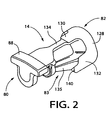
- the piston 14 includes a neck portion 80 engaging 6the swash plate 60, a head portion 82 slidably engaging the corresponding cylinder bore 12, and a connecting portion 83 which connects those neck and head portions 80, 82.
- the neck portion 80 has a groove 84 formed therein, and the swash plate 60 engages the groove 84 through a pair of hemispherical shoes 86.
- Each shoe 86 has a hemisperical surface which slidably engages a hemispherical portion of the groove 84, and a flat surface which slidably engages the corresponding one of the opposite surfaces of the swash plate 60.
- the configuration of the piston 14 will be described in detail.
- the head portion 82 cooperates with the cylinder block 10 and the valve plate 20 to define a pressurizing chamber 85.
- a rotary motion of the swash plate 60 is converted into a linear reciprocating motion of the piston 14 through the pair of shoes 86.
- a refrigerant gas in the suction chamber 22 is fed or admitted into the pressurizing chamber 85 through the suction port 40, with the suction valve 42 being opened under a reduced pressure in the cylinder bore 12.
- the refrigerant gas in the pressurizing chamber 85 is compressed by the piston 14, and the compressed gas is fed into the delivery chamber 46 through the delivery port 46, with the delivery valve 48 being opened under an elevated pressure in the pressurizing chamber 85.
- a reaction force acts on the piston 14 in the axial direction. This reaction force is received by the front housing 16 through the piston 14, swash plate 60, lug plate 62 and thrust bearing 66.
- the neck portion 80 of the piston 14 has an integrally formed rotation preventing portion 88, as shown in Fig. 2.
- the rotation preventing portion 88 is held in contact with the inner circumferential surface of the front housing 16, for preventing the piston 14 from being rotated about its centerline N.
- the cylinder block 10 has a fluid passage 94 formed therethrough, for fluid communication between the delivery chamber 24 and a crank chamber 96 which is formed between the front housing 16 and the cylinder block 10.
- a portion of the fluid passage 94 is provided by a solenoid-operated control valve 100, which is provided to control the pressure in the crank chamber 96.
- the solenoid-operated control valve 100 includes a solenoid coil 102, and a shut-off valve 104 which is opened and closed depending upon whether the solenoid coil 102 is placed in an energized state or a de-energized state.
- the shut-off valve 104 is closed when the solenoid coil 102 is energized, and is opened when the solenoid coil 102 is de-energized.
- the rotary drive shaft 50 has an exhaust passage 110 formed therethrough.
- the exhaust passage 110 is open at one of its opposite ends to the central support hole 56 indicated above, and at the other end to the crank chamber 96 through a communication passage 112.
- the central support hole 56 is held in communication with the suction chamber 22 through an exhaust port 114, which is formed through the bottom of the central support hole 56 and the valve plate 20.
- the fluid passage 94 is closed, whereby the pressurized refrigerant gas in the discharge chamber 24 is not fed into the crank chamber 96.
- the refrigerant gas in the crank chamber 96 is released into the suction chamber 22 through the exhaust passage 110 and the exhaust port 114, whereby the pressure in the crank chamber 96 is lowered, so that the angle of inclination of the swash plate 60 is increased, resulting in an increase in the rate of change of the volume of the pressurizing chamber 85 and a consequent increase in the discharge capacity of the compressor.
- the present swash plate type compressor is of a variable discharge-capacity type.
- the maximum angle of inclination of the swash plate 60 is determined by abutting contact of a stop 120 provided on the swash plate 60, with the lug plate 62.
- the minimum angle of inclination of the swash plate 60 is determined by abutting contact of the swash plate 60 with a stop 122 in the form of a ring fixed to the drive shaft 50.
- the pressure in the crank chamber 96 is controlled by controlling the solenoid-operated control valve 100 so as to selectively connect and disconnect the crank shaft 96 to and from the discharge chamber 24. With the pressure in the crank chamber 96 being changed, the angle of inclination of the swash plate 60 is changed, so that the discharge capacity of the compressor is changed.
- the operating state of the solenoid coil 102 of the solenoid-operated control valve 100 is controlled by a control device (not shown) principally constituted by a computer, depending upon appropriate input information such as a signal indicative of a load acting on the compressor.
- the cylinder block 10 and the piston 14 are formed of suitable aluminum alloys, and the outer circumferential surface of the piston 14 is coated with a coating film of a fluoro resin.
- the fluoro resin coating prevents the piston 14 from directly contacting the cylinder block 10 whose material is similar to that of the piston 14, making it possible to minimize the amount of gap between the outer circumferential surface of the piston 14 and the inner circumferential surface of the cylinder bore 12.
- the cylinder block 10 and the piston 14 may be formed of suitable hyper-eutectic crystal aluminum silicon alloys.
- the materials of the cylinder block 10, the piston 14 and the coating of the piston 14 are not limited to those mentioned above by way of example.
- the head portion 82 of the piston 14 includes a body portion 128, an outer sliding portion 130 and an inner sliding portion or protrusion 132 disposed between the body portion 128 and the neck portion 80.
- the body portion 128 has a cylindrical shape in transverse cross section, and the outer and inner sliding portions 130, 132 extend from respective circumferential portions of the body portion 128 in the radially outward and inward directions of the cylinder block 10, respectively.
- the outer and inner sliding portions 130, 132 are provided as outer and inner protrusions from the body portion 128, for sliding contact or engagement with respective circumferential portions of the inner circumferential surface of the cylinder bore 12 which correspond to respective radially outer and inner portions of the cylinder block 10.
- the inner sliding portion 132 is provided at a circumferential position of the head portion 82 at which the groove 84 of the neck portion 80 is open for engagement with the swash plate 60.
- the outer sliding portion 130 is connected to the neck portion 80 by a rib 134, while the inner sliding portion 132 is connected to the neck portion 80 by a rib 135.
- the ribs 134, 135 cooperate to constitute the connecting portion 83 indicated above.
- a total length L1 of the body portion 128 and the inner sliding portion 132 (referred to as "head inner length”, which is a length of the head portion 82 as measured at the inner sliding portion 132) is made larger than a total length L2 of the body portion 128 and the outer sliding portion 130 (referred to as “head outer length”, which is a length of the head portion 82 as measured at the outer sliding portion 130).
- head inner length which is a length of the head portion 82 as measured at the inner sliding portion 132
- head outer length which is a length of the head portion 82 as measured at the outer sliding portion 130
- the piston 14 may be formed by either joining together the head portion 82, neck portion 80 and connecting portion 83 which have been formed as separate members, as shown in Fig. 3, or forming these portions 82, 80, 83 integrally with each other.
- the percentage ⁇ is preferably at least 50%, and more preferably at least 55&, as is apparent from the graph, an increase in the head inner length L1 will results in an increase in the weight of the piston 14.
- the piston 14 has a given operating stroke. Therefore, the head inner length L1 (percentage ⁇ ) is desirably determined with those factors taken into account.
- the configuration of the inner sliding portion 132 in transverse cross section is not uniform in the axial direction. That is, the circumferential dimension of the inner sliding portion 132 as represented by a central angle is smaller at a distal sliding part 140 nearer to the neck portion 80 than at a proximal sliding part 142 nearer to the body portion 128, as indicated at ⁇ and ⁇ .
- the sliding surface pressure of the distal sliding part 140 decreases with an increase in the central angle ⁇ , the weight of the piston 14 increases with the central angle ⁇ . Accordingly, it is desirable to determine the central angles ⁇ and ⁇ with the above factors taken into account.
- the central angle ⁇ of the front sliding part 140 must be 120° or smaller, and is preferably 110° or 100° or smaller. In the present embodiment, the central angle ⁇ is 90°, while the central angle ⁇ of the proximal sliding part 142 is 120°.
- the percentage ⁇ must be at least 10%, and is preferably at least 15%, 20% or 25%. If the length of the proximal sliding part 142 is fixed, an increase in the percentage ⁇ increases an effect of preventing the inclination of the piston 14, but increases the eight of the inner sliding portion 132. Accordingly, it is desirable to determine the percentage ⁇ with these factors taken into account.
- the distal length L3 may be determined based on a percentage ⁇ of this length L3 with respect to the entire length L of the piston 14. In the present piston 14, the percentage ⁇ of the distal length L3 with respect to the entire length L is determined to be 10%.
- the percentage ⁇ must be at least 5%, and is preferably at least 8%, 10% or 12%.
- the axial position of the distal sliding part 140 is determined by the percentage ⁇ of the head inner length L1 with respect to the entire length L of the piston 14 and the percentage ⁇ of the distal length L3 with respect to the head inner length L1).
- the end of the distal sliding part 140 is spaced from the end face 136 of the piston 14 by a distance corresponding to the 40% of the entire length L.
- the total length (L1 - L3) of the body portion 128 and the proximal sliding part 142 is made equal to the head outer length L2 (total length of the body portion 128 and the outer sliding portion 130), as shown in Fig. 3.
- the distal sliding part 140 of the inner sliding portion 132 may be considered to be an extension of the proximal sliding part 142.
- the total length (L1 - L3) need not be equal to the head outer length L2, and may be different from the length L2.
- the piston 14 has the distal sliding part 140 so that the distance between the axial positions at which the reaction forces Fc, Fd act on the head portion 82 of the piston 14 can be increased, whereby the reaction force Fc corresponding to the given side force Fb can be reduced.
- the amount of increase of the mass of the piston 14 due to the provision of the inner sliding portion 132 is reduced since the distal length L3 of the distal sliding part 140 and its central angle ⁇ are minimized to such an extent that assures a surface area of the distal sliding part 140 sufficient to limit its sliding surface pressure to a value not higher than a predetermined upper limit. Accordingly, the durability of the piston 14 can be effectively increased while reducing the mass of the piston 14. Namely, the local wear and removal of the fluoro resin coating of the distal sliding part 140 can be minimized.
- the configuration of the piston 14 is not limited to the details described above with respect to the first embodiment by reference to Figs. 2-4.
- the connecting portion 83 need not include both of the ribs 134, 135, but may consist of only one of these two ribs 134, 145.
- the configuration and size of the distal sliding part 140 are not limited to the details described above with respect to the first embodiment.
- the distal sliding part 140 may have any configuration and size provided the configuration and size assure an improvement in the durability of the piston 140.
- Fig. 6 shows a piston 148 according to a second embodiment of this invention, which has a modified distal sliding part as indicated at 150.
- the distal sliding part 150 has a circumferential dimension and a central angle ⁇ which continuously decrease as indicated by a curved line in Fig. 6 as the part 150 extends in the axial direction of the piston 148 from the head portion toward the neck portion.
- Fig. 7 shows a third embodiment wherein a piston 151 has a distal sliding part 152 which consists of a wide section 154 located on the side of the neck portion, and a narrow section 156 located on the side of the head portion.
- the wide section 154 has a comparatively large central angle and consequently a comparatively large pressure-receiving surface area, which further improves the durability of the piston 151.
- the narrow section 156 contributes to a decrease in the amount of increase of the weight of the piston 151 due to the provision of the inner sliding part 152, as compared with that of a piston whose inner sliding part consists of only the wide portion 154. Only the wide portion 154 may be considered to be the distal sliding part 154, and the narrow section 156 may be considered to be a part of the proximal sliding part.
- a piston 158 has a spaced-apart distal sliding part 159 on the rib 135 which connects the proximal part 142 and the neck portion 80.
- the spaced-apart distal sliding part 159 is spaced from the proximal sliding part 142.
- the provision of the spaced-apart distal sliding part 159 eliminates a need of increasing the axial length of the proximal sliding part 142, so that the weight increase of the piston 158 due to the provision of the inner sliding portion is accordingly reduced.
- the spaced-apart distal sliding part 159 may be configured such that its central angle continuously changes in the axial direction, along a straight or curved line.
- the central angle (circumferential dimension) of the inner sliding portion 132 decrease in steps at the boundary between the proximal and distal sliding parts, in the direction from the head portion toward the neck portion 80.
- this central angle of the inner sliding portion 132 may continuously decrease at the boundary between the proximal and distal sliding parts.
- the configuration of the inner sliding portion 132 may be either symmetrical or asymmetrical with respect to a plane which passes the centerline N of the piston 14, 148, 151, 158 and the centerline M of the cylinder block 10.
- Fig. 9 shows a piston 160 according to a further embodiment of this invention, wherein the central angle ⁇ of a distal sliding part 162 is larger than the central angle ⁇ of a proximal sliding part 164, contrary to the arrangements in the preceding embodiments.
- the comparatively larger central angle (circumferential dimension) of the distal sliding part 162 provides a comparatively larger pressure-receiving surface area, which results in an effect of accordingly lowering the sliding surface pressure in the distal sliding part 162.
- the proximal sliding part 164 does not receive a large reaction force from the inner surface of the cylinder bore, and need not have a pressure-receiving surface area as large as that of the distal sliding part 162.
- the present arrangement permits an improved degree of durability of the piston 160 while assuring a reduced weight of the piston. It is noted that the provision of the proximal sliding part 164 is not essential, and that the distal sliding part 162 may be provided on the connecting portion which connects the body portion 128 of the head portion 82 and the neck portion 80.
- the various distal sliding parts described above may have suitable shapes in transverse cross section, and that the configuration of the body portion 128 is not limited to that of the illustrated embodiment.
- the body portion 128 may have an axially intermediate section which has a smaller diameter than the other axial sections. This arrangement also assures intended compression of the refrigerant gas by the piston, provided an air-tight sliding contact of the piston with the cylinder bore 12 is guaranteed at the opposite end portions of the piston.
- the construction of the swash type compressor is not limited to the details of the illustrated embodiments, but may be modified as needed.
- the solenoid-operated control valve 100 is not essential, and may be replaced by a shut-off valve which is opened and closed depending upon a difference between the pressures in the crank chamber 56 and the suction chamber 24.
- the angle of inclination of the swash plate 60 is increased to increase the discharge capacity of the compressor, by lowering the pressure in the crank chamber 56.
- Swash plate type compressor including a cylinder block having cylinder bores arranged along a circle, a drive shaft aligned with the circle, a swash plate rotated with the drive shaft, and single-headed pistons each including a head portion engaging the cylinder bore, and a neck portion engaging the swash plate, and wherein each piston is reciprocated by the swash plate rotated by the drive shaft, and the head portion includes a circular body portion, and an outer sliding portion and an inner sliding portion which are disposed between the body portion and the neck portion and which slidably engage respective circumferential portions of the cylinder bore which correspond to respective radially outer and inner portions of the cylinder block.
- Length from the end face of the body portion to the remote end of the inner sliding portion is larger than the corresponding length of the outer sliding portion.
- the inner sliding portion has a distal sliding part spaced from the end face by at least 40% of the entire piston length and having a central angle of not larger than 120° and a length of at least 5% of the entire piston length.
Landscapes
- Engineering & Computer Science (AREA)
- Manufacturing & Machinery (AREA)
- Mechanical Engineering (AREA)
- General Engineering & Computer Science (AREA)
- Compressors, Vaccum Pumps And Other Relevant Systems (AREA)
- Transmission Devices (AREA)
Applications Claiming Priority (2)
| Application Number | Priority Date | Filing Date | Title |
|---|---|---|---|
| JP11150448A JP2000337250A (ja) | 1999-05-28 | 1999-05-28 | 斜板式圧縮機 |
| JP15044899 | 1999-05-28 |
Publications (2)
| Publication Number | Publication Date |
|---|---|
| EP1055817A2 true EP1055817A2 (fr) | 2000-11-29 |
| EP1055817A3 EP1055817A3 (fr) | 2001-05-02 |
Family
ID=15497164
Family Applications (1)
| Application Number | Title | Priority Date | Filing Date |
|---|---|---|---|
| EP00111280A Withdrawn EP1055817A3 (fr) | 1999-05-28 | 2000-05-25 | Tête de piston d'un compresseur à plateau en biais avec surface de réduction de frottement |
Country Status (3)
| Country | Link |
|---|---|
| US (1) | US6484621B1 (fr) |
| EP (1) | EP1055817A3 (fr) |
| JP (1) | JP2000337250A (fr) |
Cited By (3)
| Publication number | Priority date | Publication date | Assignee | Title |
|---|---|---|---|---|
| DE10107424A1 (de) * | 2001-02-14 | 2002-09-26 | Daimler Chrysler Ag | Kolben für einen Kompressor |
| DE10145305A1 (de) * | 2001-02-14 | 2003-04-10 | Daimler Chrysler Ag | Kolben für einen Kompressor |
| CN102678864A (zh) * | 2012-05-18 | 2012-09-19 | 中山市亚泰机械实业有限公司 | 斜盘式传动机构 |
Families Citing this family (6)
| Publication number | Priority date | Publication date | Assignee | Title |
|---|---|---|---|---|
| JP2003129954A (ja) * | 2001-10-19 | 2003-05-08 | Toyota Industries Corp | 流体機械用ピストンおよび流体機械 |
| JP4194350B2 (ja) * | 2002-11-26 | 2008-12-10 | サンデン株式会社 | 斜板式圧縮機 |
| US20040149123A1 (en) * | 2002-12-18 | 2004-08-05 | Kiyokazu Yamamoto | Piston compressor |
| US6941852B1 (en) * | 2004-02-26 | 2005-09-13 | Delphi Technologies, Inc. | Unitary hollowed piston with improved structural strength |
| JP5492917B2 (ja) * | 2012-02-01 | 2014-05-14 | 株式会社豊田自動織機 | 可変容量型斜板式圧縮機 |
| JP2017180291A (ja) * | 2016-03-30 | 2017-10-05 | 株式会社豊田自動織機 | 両頭ピストン型斜板式圧縮機 |
Citations (1)
| Publication number | Priority date | Publication date | Assignee | Title |
|---|---|---|---|---|
| JPH11150448A (ja) | 1997-11-18 | 1999-06-02 | Sony Corp | 発振回路 |
Family Cites Families (9)
| Publication number | Priority date | Publication date | Assignee | Title |
|---|---|---|---|---|
| JP2684931B2 (ja) | 1992-08-21 | 1997-12-03 | 株式会社豊田自動織機製作所 | 片頭ピストン型圧縮機 |
| JP2924564B2 (ja) | 1993-05-28 | 1999-07-26 | 株式会社豊田自動織機製作所 | 揺動斜板式圧縮機におけるピストン |
| JP2924621B2 (ja) | 1993-12-27 | 1999-07-26 | 株式会社豊田自動織機製作所 | 揺動斜板式圧縮機におけるピストン |
| JP3550707B2 (ja) | 1993-12-27 | 2004-08-04 | 株式会社豊田自動織機 | 揺動斜板式圧縮機におけるピストン |
| JP3631344B2 (ja) | 1995-11-24 | 2005-03-23 | カルソニックカンセイ株式会社 | 斜板式コンプレッサ |
| EP0780572B1 (fr) * | 1995-11-24 | 2005-10-12 | Calsonic Kansei Corporation | Compresseur à plateau en biais |
| JPH09250451A (ja) | 1996-03-19 | 1997-09-22 | Sanden Corp | 容量可変型揺動斜板式圧縮機のピストン |
| US5630353A (en) | 1996-06-17 | 1997-05-20 | General Motors Corporation | Compressor piston with a basic hollow design |
| JPH10169557A (ja) | 1996-12-06 | 1998-06-23 | Toyota Autom Loom Works Ltd | 圧縮機 |
-
1999
- 1999-05-28 JP JP11150448A patent/JP2000337250A/ja active Pending
-
2000
- 2000-05-24 US US09/575,471 patent/US6484621B1/en not_active Expired - Fee Related
- 2000-05-25 EP EP00111280A patent/EP1055817A3/fr not_active Withdrawn
Patent Citations (1)
| Publication number | Priority date | Publication date | Assignee | Title |
|---|---|---|---|---|
| JPH11150448A (ja) | 1997-11-18 | 1999-06-02 | Sony Corp | 発振回路 |
Cited By (4)
| Publication number | Priority date | Publication date | Assignee | Title |
|---|---|---|---|---|
| DE10107424A1 (de) * | 2001-02-14 | 2002-09-26 | Daimler Chrysler Ag | Kolben für einen Kompressor |
| DE10145305A1 (de) * | 2001-02-14 | 2003-04-10 | Daimler Chrysler Ag | Kolben für einen Kompressor |
| US6925925B2 (en) | 2001-02-14 | 2005-08-09 | Daimlerchrysler Ag | Piston for a compressor |
| CN102678864A (zh) * | 2012-05-18 | 2012-09-19 | 中山市亚泰机械实业有限公司 | 斜盘式传动机构 |
Also Published As
| Publication number | Publication date |
|---|---|
| EP1055817A3 (fr) | 2001-05-02 |
| JP2000337250A (ja) | 2000-12-05 |
| US6484621B1 (en) | 2002-11-26 |
Similar Documents
| Publication | Publication Date | Title |
|---|---|---|
| US6752065B2 (en) | Sliding member and sliding device | |
| US5765464A (en) | Reciprocating pistons of piston-type compressor | |
| KR100274497B1 (ko) | 압축기 | |
| US5974946A (en) | Swash plate type compressor using swash plate made of highly wear-resistant material | |
| US5953980A (en) | Piston type compressors | |
| US6484621B1 (en) | Swash plate type compressor wherein piston head has inner sliding portion for reducing local wear | |
| EP0952340A2 (fr) | Piston pour un compresseur à plateau en biais pour réfrigérant | |
| US6254356B1 (en) | Fitting structure for controlling valve in variable capacity compressor | |
| EP0844389B1 (fr) | Compresseur à plateau en biais | |
| US6546841B2 (en) | Swash plate compressor and piston therefor | |
| US6393964B1 (en) | Compressor having piston rotation restricting structure with lubricating inclined guide surface | |
| US6508633B2 (en) | Swash plate type compressor of variable capacity type | |
| EP0849470B1 (fr) | Compresseur à plateau en biais capable d'assurer une lubrification suffisante entre un piston et un patin de piston disposé à glissement entre le piston et le plateau en biais | |
| US6575080B1 (en) | Single-headed piston for swash plate type compressor wherein head portion has a curved surface at axial end | |
| EP0856663A2 (fr) | Compresseur à plateau en biais à capacité variable | |
| US6332394B1 (en) | Piston for swash plate type compressor, wherein head portion includes radially inner sliding projection connected to neck portion | |
| US6293761B1 (en) | Variable displacement swash plate type compressor having pivot pin | |
| JP5492917B2 (ja) | 可変容量型斜板式圧縮機 | |
| JPH08254180A (ja) | 斜板式圧縮機 | |
| JPH09177670A (ja) | ピストン式圧縮機 | |
| JP2001159392A (ja) | 斜板式圧縮機用の片頭ピストン | |
| EP1188923B1 (fr) | Revêtement d'un plateau-came d'un compresseur | |
| EP1039128A2 (fr) | Compresseur à plateau en biais | |
| JP3084976B2 (ja) | 片側ピストン式可変容量圧縮機における潤滑構造 | |
| EP1275846A2 (fr) | Dispositif d'articulation pour un plateau en biais |
Legal Events
| Date | Code | Title | Description |
|---|---|---|---|
| PUAI | Public reference made under article 153(3) epc to a published international application that has entered the european phase |
Free format text: ORIGINAL CODE: 0009012 |
|
| 17P | Request for examination filed |
Effective date: 20000525 |
|
| AK | Designated contracting states |
Kind code of ref document: A2 Designated state(s): DE FR IT |
|
| AX | Request for extension of the european patent |
Free format text: AL;LT;LV;MK;RO;SI |
|
| PUAL | Search report despatched |
Free format text: ORIGINAL CODE: 0009013 |
|
| AK | Designated contracting states |
Kind code of ref document: A3 Designated state(s): AT BE CH CY DE DK ES FI FR GB GR IE IT LI LU MC NL PT SE |
|
| AX | Request for extension of the european patent |
Free format text: AL;LT;LV;MK;RO;SI |
|
| RAP1 | Party data changed (applicant data changed or rights of an application transferred) |
Owner name: KABUSHIKI KAISHA TOYOTA JIDOSHOKKI |
|
| AKX | Designation fees paid |
Free format text: DE FR IT |
|
| 17Q | First examination report despatched |
Effective date: 20040819 |
|
| STAA | Information on the status of an ep patent application or granted ep patent |
Free format text: STATUS: THE APPLICATION IS DEEMED TO BE WITHDRAWN |
|
| 18D | Application deemed to be withdrawn |
Effective date: 20050301 |