EP1055838A2 - Mécanisme vibratoire - Google Patents
Mécanisme vibratoire Download PDFInfo
- Publication number
- EP1055838A2 EP1055838A2 EP00111162A EP00111162A EP1055838A2 EP 1055838 A2 EP1055838 A2 EP 1055838A2 EP 00111162 A EP00111162 A EP 00111162A EP 00111162 A EP00111162 A EP 00111162A EP 1055838 A2 EP1055838 A2 EP 1055838A2
- Authority
- EP
- European Patent Office
- Prior art keywords
- vibration
- spring
- magnets
- input
- seat
- Prior art date
- Legal status (The legal status is an assumption and is not a legal conclusion. Google has not performed a legal analysis and makes no representation as to the accuracy of the status listed.)
- Granted
Links
Images


























Classifications
-
- F—MECHANICAL ENGINEERING; LIGHTING; HEATING; WEAPONS; BLASTING
- F16—ENGINEERING ELEMENTS AND UNITS; GENERAL MEASURES FOR PRODUCING AND MAINTAINING EFFECTIVE FUNCTIONING OF MACHINES OR INSTALLATIONS; THERMAL INSULATION IN GENERAL
- F16F—SPRINGS; SHOCK-ABSORBERS; MEANS FOR DAMPING VIBRATION
- F16F15/00—Suppression of vibrations in systems; Means or arrangements for avoiding or reducing out-of-balance forces, e.g. due to motion
- F16F15/02—Suppression of vibrations of non-rotating, e.g. reciprocating systems; Suppression of vibrations of rotating systems by use of members not moving with the rotating systems
- F16F15/03—Suppression of vibrations of non-rotating, e.g. reciprocating systems; Suppression of vibrations of rotating systems by use of members not moving with the rotating systems using magnetic or electromagnetic means
-
- F—MECHANICAL ENGINEERING; LIGHTING; HEATING; WEAPONS; BLASTING
- F16—ENGINEERING ELEMENTS AND UNITS; GENERAL MEASURES FOR PRODUCING AND MAINTAINING EFFECTIVE FUNCTIONING OF MACHINES OR INSTALLATIONS; THERMAL INSULATION IN GENERAL
- F16F—SPRINGS; SHOCK-ABSORBERS; MEANS FOR DAMPING VIBRATION
- F16F6/00—Magnetic springs; Fluid magnetic springs, i.e. magnetic spring combined with a fluid
- F16F6/005—Magnetic springs; Fluid magnetic springs, i.e. magnetic spring combined with a fluid using permanent magnets only
Definitions
- the present invention relates to a vibration mechanism having a magneto-spring that can be used for a vibration isolator such, for example, as a suspension unit, a cab mount, an engine mount or the like.
- magnetic levitation damping technology makes it possible to support physical objects with no actual physical contact, its merits include reduction of problems related to friction and wear, the capability for motion at very high speeds, and low levels of vibration and noise. Moreover, it can be used in special situations (also a special characteristic of magnets), as well as having the advantage of its force being effective in all directions. For those reasons, magnetic levitation vehicles, magnetic bearings, etc. which apply these special characteristics are being developed.
- the present invention has been developed to overcome the above-described disadvantages.
- the vibration mechanism according to the present invention includes first and second permanent magnets spaced from each other, and the second permanent magnet is movable relative to the first permanent magnet.
- the first and second permanent magnets constitute a repulsive magneto-spring having a spring constant, wherein magnetic energy accumulated in the magneto-spring is made substantially constant by appropriately selecting a locus of motion of the second permanent magnet relative to the first permanent magnet, thereby setting the spring constant to substantially zero.
- each of the first and second permanent magnets is a multi-pole magnet, a leakage magnetic field created between neighboring magnet poles can be effectively utilized, resulting in an efficient magneto-spring.
- the repulsive force acting between the first and second permanent magnets is made substantially constant by appropriately selecting a relationship between the opposing area of the first and second permanent magnets and the distance between the first and second permanent magnets.
- the construction is very simple, vibration can be effectively absorbed by making use of a phase shift.
- the first permanent magnet is secured to a stationary frame
- the second permanent magnet is secured to a movable frame movably mounted on the stationary frame.
- first and second permanent magnets are inclined on the stationary and movable frames, respectively, the opposing area of the magnets can be easily changed depending on the distance between the magnets, making it possible to simplify the construction of the vibration mechanism.
- the origin of electromagnetic force is Lorentz force, which controls electrical charge's velocity vectors within a homogeneous magnetic field (electrical field).
- the forces that exist between two magnets follow Coulomb's law, and the concept of a "field" of force can be introduced.
- This field occurs when magnetic charge creates a field called the "magnetic field” around a magnet, which is in turn sensed by another magnet's magnetic charge. If the field is controlled satisfactorily, it is conceivable that the field may bring itself into a steady state, and disturbance may be cancelled out by a passive control.
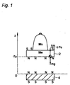
- a pair of permanent magnets 2, 4 such, for example, as rare-earth magnets (Nd-Fe-B) are faced to repel each other.
- the repulsive forces between the magnetic poles 2, 4 create fluctuations in energy accumulated by the work produced when the magnetic poles 2, 4 are shifted.
- the amount of fluctuation is equal to the quantity of work.
- the magnetic energy accumulated per unit volume of magnetic field space can be found using the following equation:
- the repulsive force of two faced magnets 2, 4 with like poles can be found using the following equation: In these equations, 'B' is the magnetic flux density, 'A' is the area of the magnetic poles, and ⁇ 0 is the magnetic permeability.
- the repulsive force is proportional to the square of the magnetic flux density 'B' and to the area 'A'.
- the magnetic flux Hm indicates the diamagnetic field of the force by which the magnet weakens itself (self-demagnetization), and Hex is the external magnetic field that arises when magnetic poles oppose one another.
- multi polarization is effective to reduce Hm by creating a sequential (quasi) magnetic field with the neighboring magnets.
- the magnetic line of force will not extend outward.
- the number of poles is increased to decrease the Hm, the gradient of the magnetic line of force with respect to the tangential vector at the boundary surface is lost, and the magnetic line of force around a magnetic domain wall almost completely stops extending outward.
- the magnetic flux density at the edges is reduced, weakening the repulsive force.
- the strength of the repulsive force is determined by the area of the opposing surfaces, the number of poles and the distance between the magnets that is normally used.
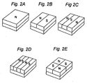
- Figs. 2A to 2E depict various magnets each having an area of 75x75mm 2 and a thickness of 20mm with the number of poles ranging from one to four.
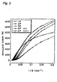
- Fig. 3 depicts a relationship between the repulsive force and the distance between the magnets when they are disposed in the same manner as in Fig. 1.
- Single-pole magnets provide an almost homogeneous magnetic field, while two-pole magnets are controlled in magnetic flux and have a leakage magnetic field between the neighboring magnets, wherein an X-shaped magnetic flux distribution portion has a high magnetic flux density.
- Table 1 shows spring constants and spring forces of such magnets.
- an efficient magnetic circuit for a mechanism that is damping vibration across several 10's of mm's of magnet deflection with a seated occupant whose mass is approximately 100kg would be the two-pale magnet. It has a repulsive force to reduce the "bottoming" sensation, when the distance between the magnets is approximately 5mm, and it also has a high repulsive force when the distance between the magnets exceeds 20mm, in the case of the occupant's body absorbing the vibration. Moreover, in the two-pole magnet, a leakage magnetic field is created between the magnets, and when the faced magnets are brought closer, a stronger repulsive force is achieved, reducing the sensation of bottoming. If the mechanism is designed such that the influence of the leakage magnetic field is reduced in the steady state, while the leakage magnetic field is utilized in the unsteady state, the leakage magnetic field can be used for a magnetic force to shift the fielded to the steady state.
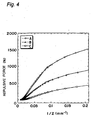
- Fig. 4 shows a relationship between the distance between the magnets (z) and the static repulsive force (Fmg) expressed by formula (4), when magnets of different size and mass are put in motion in the direction perpendicular to their surfaces.
- the internal magnetic moment is not easily affected by the magnetic field, and the strength of magnetization on a demagnetization curve barely fluctuates, and nearly completely maintains the saturation magnetization strength. For that reason, when the magnetic charge is evenly dispersed at the end surfaces of magnets, a hypothesized charge model is used in calculating the repulsive force acting between the magnets.
- (l) and (d) indicate the size of a magnet and ⁇ is the amount by which the two magnets are offset from each other, provided that the origin for calculation is located at the center point of the lower magnet.
- f m when the natural frequency is f m , f m is given by the following equation:
- the natural frequency is directly proportional to If an optimum load-deflection characteristic curve is set by adjusting the equilibrium point and the magnetic circuit, the resonance frequency can be nearly completely fixed, irrespective of the loaded mass.
- the portion where the spring constant k m is large can be utilized to reduce the resonance frequency.
- Fig. 6 shows results of calculation of a load-gap relationship when the locus of motion has been changed, as shown in Fig. 7.
- the magnet A in Fig. 4 was used.
- the magnets were inclined 15° with respect to the horizontal direction so that the direction in which the maximum repulsive force acts forms an angle of 15° with respect to the vertical direction.
- the repulsive force in that case is shown in Fig. 9.
- Fz indicates the repulsive force perpendicular to the faced magnet area
- Fx indicates the horizontal repulsive force, which is in turn converted into either an upward or downward force through the links.
- the magnets were disposed such that the opposing area thereof is maximized at a magnet distance of 0mm, and the point of equilibrium is at a magnet distance of 15mm apart.
- the dynamic spring constants were obtained for each locus of motion and for each arrangement of the magnets.
- the locus of motion of the magnets changes the dynamic spring constant.
- ⁇ ( ⁇ ) indicate the measured values when the magnets were inclined at angles of 0, 30, and 45 degrees, respectively, and ⁇ correspond to the arrangement of Fig. 11A, while ⁇ correspond to the arrangement of Fig. 11B.
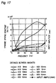
- Figs. 17 and 18 show the dynamic spring constant and damping coefficient of the magneto-springs, respectively, when a magneto-spring system composed of two-pole magnets with an opposing area of 75 x 75mm 2 and a thickness of 15mm (A15), 20mm (A20), or 25mm (A25) was moved vertically at various frequencies and at different input deflection amplitudes. While they are affected by the frequency, the dynamic spring constant and damping coefficient are dependent on the size of the magnets and the distance between them. In other words, the dynamic spring constant and damping coefficient can be controlled by controlling the size of the magnets and the distance between them. By utilizing these various characteristics, the resonance frequency will fluctuate due to differences in input acceleration amplitude, and a transfer function with a constant output acceleration amplitude can be made, making it possible to realize various types of passive control.
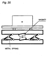
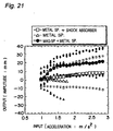
- Fig. 21 depicts the behavior of the equilibrium point of the single-degree-of-freedom model of Fig. 20) under varying acceleration of 2Hz-excitation frequency.
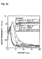
- Fig. 22 depicts the vibration characteristics and simulation results of an experiment in which a one-degree-of-freedom non-linear model of the magneto-spring and a linear model composed of metal springs and shock absorbers were each loaded with 90kg mass, and then excited by random waves that simulated the acceleration at the floor of a one-box type vehicle traveling over the highway (Japan) at a speed of 80km/hr. The results of this simulation very closely duplicate the actual measurements that were taken. Furthermore, it has the same resonance point as the non-linear model of the magneto-spring.
- Fig. 22 also depicts the simulation results of a linear model, in which the spring constant and damping coefficient do not fluctuate.
- Fig. 23 depicts an analysis model of the magneto-spring non-linear model and parameters. The parameters were determined based on the experimental results of the dynamic characteristics derived by a fatigue durability machine and on the load-deflection characteristics of the magneto-spring.
- Fig. 24 depicts a vertical suspension using a magneto-spring (hereinafter referred to as VSUM).
- the VSUM supports the human body and a seat and is composed of metal springs and a magneto-spring that continue small vibrations, and a bottoming and topping buffer.
- the magneto-spring includes a pair of inclined permanent magnets secured respectively to a lower frame and an upper frame vertically movably mounted on the lower frame via pantograph-type link mechanisms disposed on respective sides of the VSUM, while the metal springs includes a metal spring A connected at opposite ends thereof to one of the pantograph-type link mechanisms and a plurality of metal springs B connected to a portion of the upper frame.
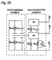
- the bottoming and topping buffer includes a shock absorber connected at opposite ends thereof to the other pantograph-type link mechanism. It has been proposed that evaluation of the dynamic performance of the suspension seat would be done based on the isolation characteristics under random excitation and on the performance of the bottoming buffer. For that reason, the VSUM seat is designed using two separate mechanical elements exhibiting vibration-isolation performance and shock-absorbing performance, respectively.
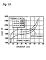
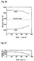
- the characteristics of the VSUM seat are created using the static characteristics of the magneto-spring shown in Figs. 6, 7, 8, 9, and 19, while the amount of deflection amplitude of the load-deflection characteristics is maintained at a lower level.
- a magneto-spring system composed of rare-earth magnets differs from ferrite magnets in that because the magnet itself is also a conductor, eddy currents are produced due to electromagnetic induction, thereby causing a braking force to act in the direction in which the movement of the magnet is restricted.
- the magnetic field gradient and magnetic flux density also fluctuate.
- the magnetic flux density decreases due to heat generation by the eddy currents.
- the VSUM magneto-spring consists of permanent magnets with an opposing area of 75x75mm 2 and a thickness of 20mm.
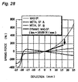
- Fig. 28 shows the characteristics of a spring system constituting the VSUM
- Fig. 29 shows the load-deflection characteristics obtained by combining all spring forces.
- the VSUM is required to accommodate the range of 1.5 times the loaded mass within a stroke range of the load-deflection characteristics.
- the metal spring A is employed for the purpose of creating a negative spring constant at the equilibrium point.
- the metal springs B are used to make adjustments for the loaded mass.
- the magneto-spring creates a non-linear damping coefficient through phase shifts by utilizing the dynamic spring characteristics that are dependent on amplitude, the non-linear spring force that withstands input, and the small spring constant of a combination spring.
- Fig. 30 is the result of a VSUM phase shift analysis from an experiment in which the VSUM was excited in a range of 2 ⁇ 10Hz by a sine wave with deflection amplitude of 3mm.
- the VSUM is a mechanism in which the phase shift lags up to needy 160° close to the opposite phase at 4 Hz, and vibration energy is attenuated by the phase shifts.
- the new equilibrium point B has a smaller spring constant than equilibrium paint A, and the VSUM seat's resonance frequency is also lower than the resonance frequency of static equilibrium point A. If a large forced deflection is applied at equilibrium point B (which is in a state of very small vibration, has a small spring constant, and is unstable under deflection excitation), the new deflection excitation force will cause the VSUM seat to undergo a large relative deflection.
- the loaded mass and the shock absorber curb that relative deflection (deflection in the direction opposing gravity). If deflection occurs in the direction of gravity, it is repelled by the magnetic field's gradient.
- the shock absorber is used for damping the vibration, and over convex surfaces, there's a lag in reaction time. This causes a sensation of being pulled upward to remain.
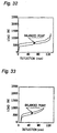
- Seat A of Fig. 32 has a small spring constant of 2650 N/m and a large suspension stroke of 130 mm. This is an air suspension seat, with excellent vibration absorption and shock absorption.
- Seat B of Fig. 33 has a small spring constant of 3250 N/m and a small suspension stroke of 100 mm. Additionally, because shock absorption is achieved by a shock absorber with a low damping force, this is an air-suspension seat that lays an emphasis on its vibration absorbing properties.
- Seat C of Fig. 34 is a magneto-spring suspension seat having a non-linear spring constant and also having a stroke of half the conventional suspension stroke, wherein no load-deflection adjustment is required with respect to the loaded mass.
- FIG. 35 has a spring constant of 4940 N/m and a reduced suspension smoke of 95 mm, and includes a shock absorber having a large damping force.
- This seat is a metal spring suspension seat which attempts to optimize both the vibration and shock absorption properties.
- Seat E of Fig. 36 has a spring constant of 4590 N/m and a reduced suspension stroke of 75 mm, and includes a shock absorber having a large damping force.
- This seat is also a metal spring suspension which attempts to optimize both the vibration and shock absorbing properties.
- Seat F of Fig. 37 has a spring constant of 6930 N/m and a reduced suspension stroke of 75 mm, and includes a shock absorber having a small damping force.
- This seat is a metal spring suspension seat that lays emphasis on its vibration absorbing properties.
- Seat G of Fig. 38 is a metal spring suspension seat which aims at shock absorption through a combination of a shock absorber with a low damping force and a spring constant of 7100 N/m, along with a suspension stroke of 135 mm, and also aims at optimum vibration absorption.
- Seat H of Fig. 39 is also a metal spring suspension seat and mainly focuses on shock absorption, with a combination of a spring constant of 10550 N/m, and a shock absorber with a large damping force.
- the VSUM seat has the load-deflection characteristics shown in Fig. 29.
- Exciting waveforms were determined based on test runs that were carried out using a van-type vehicle on the highways in Japan. There were used various random waves as shown in Table 4 and reproduced by an electromotive triaxial exciter from vertical acceleration of a vehicle floor at a position above the rear axle, and transformed sine waves of 2 Hz frequency and 15 m/s 2 acceleration amplitude reproduced by a uniaxial hydraulic exciter and obtained from DR-12 random waves shown in Table 4 by multiplying the largest shock waves' acceleration amplitude by 1.2.
- Figs. 40 and 41 show the special characteristics of the exciting waveforms in Table 4 and show the travel speed of the van-type vehicle and overall values of input acceleration in the range of 0 ⁇ 50 Hz, as well as the maximum input acceleration amplitude in acceleration time series data.
- the metal-spring suspension seats with a small stroke generally have a tendency toward bottoming when a large impact force is applied.
- the air suspension seats have a larger suspension stroke, and bottoming (bottom stop impact) is alleviated by attenuating an impact force with the shock absorber.
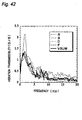
- Fig. 42 shows the frequency characteristics (when excited by DR-12 random input) of the air suspension seat shown in Table 3, the metal spring seats A, B, D, and F, which exhibit typical vibration characteristics for that seat type, and the VSUM seat.
- the weight of the subject was 82kg.
- Figs. 43 and 44 show the results of an evaluation done on transient ride comfort in relation to impulsive input, similar to going over bumps on a road.
- Fig. 43 is a graph when vibration of 1.5 Hz and 5 m/s 2 was input.
- Fig. 44 is a graph when impulsive vibration of 2 Hz and 15 m/s 2 was input.
- Seat A exhibits both vibration and shock absorption. This seat is difficult to undergo the bottoming and has superior vibration characteristics over all frequency ranges.
- Seat B has a low resonance frequency, but exhibits a high vibration transmissibility of 2.15 (G/G). It has a strong spring feeling and is excellent for vibration absorption, but problems remain with its shock absorption qualities.
- the transmissibility is high in the frequencies beyond 5 Hz due to the effect of its shock absorber. Although its vibration characteristics are not so good, it is a suspension seat with good shock absorption, even in the smaller stroke ranges.
- Seat F has excellent vibration absorption properties, but because its damping system utilizes phase shifts caused by a shock absorber of which the damping force changes between the expanding and contracting directions, its shock absorbing qualities are lacking, and bottoming occurs.
- the shock absorber of the VSUM seat does not work when 5 m/s 2 vibration has been input at 1.5 Hz, but works when 15 m/s 2 impact vibration has been input at 2 Hz.
- the shock absorber of the VSUM seat is also set at a large damping coefficient, so it has very effective impact-absorbing qualities in the smaller stroke range.
- the VSUM seat has a spring constant of 10000 N/m at the equilibrium point when the loaded mass is subjected to very small vibration. This is a bit higher than that of the conventional suspension seat. Because damping is achieved through phase shifts, the VSUM seat has goad vibration absorbing qualities in the lower frequency range.
- V is the travel speed (m/s) and L is the wheel base (m).
- L is the wheel base (m).
- a vehicle traveling at 80 km/h will receive shock input when going over seams in the road, or rough surfaces. This input ranges from 7 Hz to 10 Hz, and is an impulsive or periodic input. Because the VSUM seat utilizes damping by the phase shifts, it isn't equipped to handle this type of impulsive input as well, so its acceleration increases. However, the acceleration transmissibility is lower than 0.5 G/G, and as can be seen from Figs. 43 and 44, it exhibits excellent shock absorption, so the acceleration is held to a low level, and doesn't significantly effect to the ride comfort.
- Fig. 45 shows the frequency characteristics of seats A and B, and the VSUM seat when input spectrum DR-1 was applied.
- the weight of the subject was 60kg.
- the air suspension seat with it's good vibration characteristics
- the VSUM seat when exposed to small input acceleration of DR-1's input spectrum, the VSUM exhibits characteristics in the lower frequency ranges that are completely unique compared to any other seats.
- the resonance crest which is near 2 to 3 Hz, is damped by the phase shift, so the vibration transmissibility is held to a low level of 1.0 (G/G).
- phase shifts are facilitated up to nearly 3 Hz by the energy reviving and amplifying effects of the magneto-spring utilizing input vibration.
- transmissibility is slightly high at a resonant crest (1.3 (G/G)), it has nearly the same vibration characteristics as the air suspension seat having a 130mm stroke.
- Fig. 46 depicts the frequency characteristics in the vertical direction of the VSUM seat when traveling over highway roads as stated in Table 4.
- the non-linear magneto-spring characteristics exhibit little dependency on the input, and a high level of robustness is evident.
- Fig. 47 depicts the results of an investigation of vibration transmissibility characteristics caused by the differences in input acceleration amplitude.
- the phase shift lags even in the low frequency range.
- the transmissibility at the resonant crest is close to 1.0 (G/G), and the transfer function closely resembles quasi-active controls.
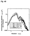
- Fig. 48 shows the weighted ride comfort evaluation done on seats shown in Fig. 42 based on ISO2631-1; 1997(E). Excitation was caused by random input DR-12, and the weight of the subject was 82kg.
- vibrational energy is absorbed, and the occupant felt little fatigue: at 0-2 Hz, a "wavy" motion that causes motion sickness; at around 5 Hz, a “bobbing” motion in which mainly the torso and vision are affected; at around 10 Hz, a shaking motion felt mainly in the lower limbs, at around 20 Hz, a pounding motion that is accompanied by noise; and at 30 Hz and above, a "buzzing" type of vibration.
- the acceleration at around 8 Hz where the resonance of internal organs occurs is slightly high, but does not reach a level that would be considered a problem.
- the air suspension exhibits excellent vibration absorption in the higher frequency ranges and the VSUM exhibits excellent vibration absorption in the range below 2 Hz, in which a wavy motion occurs.
- the VSUM seat achieves approximately the same vibration absorbing capability as the air suspension seat, but with a stroke only half as long as that of the air suspension seat.
- the value of a w mentioned in ISO2631-1: 1997(E), is nearly the same as well.
- a w is the sum total of the acceleration from 0 to 50 Hz with weighed spectra and is given by the following equation: Wi is the weighted spectra function, per ISO2631-1: 1997(E), and a i indicates actual measured acceleration, in which a frequency analysis was done on the vertical vibration at the occupant's hip joint.
- Fig. 32 The vibration characteristics of several suspension seats according to ISO 2631-1: 1997(E) (weighted spectra)
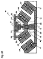
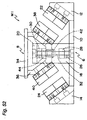
- Figs. 49 to 53 depict a vibration mechanism M1 according to a first embodiment of the present invention.
- the vibration mechanism M1 includes a stationary frame 6 and a movable frame 8 vertically movably mounted on the stationary frame 6.
- the stationary frame 6 includes a generally rectangular base plate 10, a pair of inclined stands 12, 14 secured to opposite ends of the base plate 10, respectively, a pair of side plates 16, 18 secured at lower ends thereof to respective sides of a central portion of the base plate 10, and an upper stationary plate 20 secured to upper ends of the side plates 16, 18.
- the inclined stands 12, 14 are inclined downwardly towards the inside and each of them has a two-pole magnet 22, 24 shown in, for example, Fig. 2B and secured to an upper surface thereof.
- a lower stopper 28 is secured to the center of the base plate 10 via a spacer 26, while an upper stopper 30 is secured to the center of the upper stationary plate 20.
- the lower stopper 28 and the upper stopper 30 hold lower and upper ends of a slide shaft 32, respectively.
- the movable frame 8 includes a top plate 34, a generally V-shaped bracket 36 secured to a lower surface of the top plate 34, and two two-pole magnets 38, 40 secured to inclined portions 36a, 36a formed on respective sides of the bracket 36.
- a slide bearing 42 and a contact member 44 are mounted to a lower portion of the bracket 36, and the slide shaft 32 is loosely inserted into the slide bearing 42.
- the two-pole magnets 22, 24 secured to the inclined stands 12, 14 are spaced from and extend parallel to the two-pole magnets 38, 40 secured to the bracket 36, respectively, with like magnetic poles opposed to each other.
- the movable frame 8 can move vertically along the slide shaft 32 between the bottom dead center, at which the slide bearing 42 is brought into contact with the lower stopper 26, as shown in Fig. 51, and the top dead center at which the contact member 44 is brought into contact with the upper stopper 30, as shown in Fig. 52.
- the vibration mechanism M1 can be used for a vibration isolating mechanism such, for example, as a suspension unit, an engine mount or the like.
- a vibration isolating mechanism such, for example, as a suspension unit, an engine mount or the like.
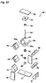
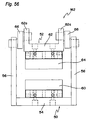
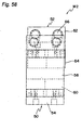
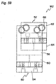
- Figs. 54 to 59 depict a vibration mechanism M2 according to a second embodiment of the present invention, which includes a stationary frame 50 and a movable frame 52 rotatably mounted on the stationary frame 50.
- the stationary frame 50 includes a base plate 54, a pair of side plates 56, 58 secured at lower ends thereof to opposite ends of the base plate 54, and a two-pole magnet 60 secured to the center of the base plate 54.
- the movable frame 52 includes a generally U-shaped rocking member 62 and a two-pole magnet 64 secured to a lower surface of the rocking member 62.
- the two-pole magnet 64 confronts the two-pole magnet 60 on the stationary frame 50 with like magnetic poles opposed to each other.
- the rocking member 62 has two opposing side walls 62a, 62a each having two round holes 62b, 62b defined therein.
- One end of a crank shaft 66 is loosely inserted into each round holes 62b, while the other end of the crank shaft 66 is similarly loosely inserted into a round hole 56a (or 58a) defined in an upper portion of the side plate 56 (or 58) of the stationary frame 50.
- the spring constant around the equilibrium point can be set to nearly zero (k ⁇ 0) within a predetermined range in which the opposing area decreases as the upper magnet 64 moves towards the lower magnet 60 or within another predetermined range in which the opposing area increases as the upper magnet 64 moves away from the lower magnet 60 (for example, within a range from Fig. 58 to Fig. 59), by appropriately selecting the size of the two-pole magnets 60, 64 and the radius of rotation of the crank shafts 66, ⁇ , 66 depending on a loaded mass placed on the movable frame 52.
- the two two-pole magnets 60, 64 are disposed horizontally, they may be inclined as in the vibration mechanism M1 so long as they extend parallel to each other.
- vibration mechanisms M1, M2 shown in Figs. 49 to 59 a plurality of two-pole magnets 22, 24, 38, 40, 60, 64 are used, other multi-pole magnets shown in Figs. 2C, 2D, and 2E may be used.
- Fig. 60 is a graph indicating a relationship between the load and the gap or distance between the magnets when one of the two two-pole magnets having an opposing area of 75x75mm 2 and a thickness of 20mm has been shifted relative to the other in a parallel state with like magnetic poles opposed to each other. The amount of shift was changed by 5mm in the range of 0-75mm.
- lines A and B indicate loads of 500N and 1000N, respectively. If one of the magnets is moved relative to the other in a manner in which the relationship between the amount of shift and the amount of gap follows one of those tines (by appropriately selecting the locus of motion), the load can be made constant or the spring constant can be set to nearly zero (k ⁇ 0).
- Fig. 61 is a graph indicating a relationship between the load and the gap or distance between the magnets when one of the two two-pole magnets having an opposing area of 75x75mm 2 and a thickness of 20mm has been shifted relative to the other from a state in which like magnetic poles are opposed to each other so that the opposing area of opposite magnetic poles may increase gradually.
- the amount of shift was changed by 2.5mm in the range of 0-17.5mm.
- lines C and D indicate loads of 500N and 1000N, respectively.
- the toad can be made constant or the spring constant can be set to nearly zero (k ⁇ 0) by appropriately selecting the tows of motion of one of the two-pole magnets relative to the other.
- the constant load (the repulsive force given by Equation (2) is constant) is achieved, for example, by increasing the opposing area with an increase in the amount of gap so that the accumulated magnetic energy may be made substantially constant.
- the load can be made constant over a wide gap range, making it possible to provide a vibration mechanism having a large stroke.
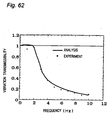
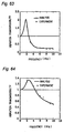
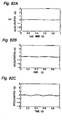
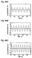
- Figs. 62, 63 and 64 depict the frequency characteristics of a magneto-spring model having a spring constant of approximately zero, those of a metal spring model, and those of a metal spring-damper model, respectively.
- the magneto-spring model having a spring constant of approximately zero has no resonant point in the tow-frequency region and is, hence, superior in shock absorption, and also provides a good vibration isolating performance even in the high-frequency region, while the metal spring model or the metal spring-damper model has a resonant point in the low-frequency region and is inferior to the magneto-spring model in shock absorption.
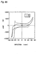
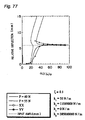
- Fig. 65 depicts the load-deflection characteristics (measured vales) of vibration models in the form of XX or YY.
- the model XX has two X-shaped links on each side of the vibration model of Fig. 20, wherein the mounting angle of the magnets is 0° and the stroke between the top and bottom dead centers is 70mm.
- the model YY has two Y-shaped links on each side of the vibration model, as shown in Fig. 20, wherein the mounting angle of the magnets is 10° and the stroke between the top and bottom dead centers is 50mm.
- the model XX has a smaller hysteresis loss including structural damping and frictional damping than that of the model YY.
- the phase curve shifts from [YY] to [XX]. Accordingly, an anti-phase occurs easily even in the low-frequency region, reducing the vibration transmissibility and improving the vibration isolating performance.
- the phase shift ( ⁇ ) is given by:
- the relative displacement is affected by the hysteresis loss.
- the experimental values and the vibration transmissibility were calculated from the vertical acceleration on the platform of the exciter and the vertical acceleration of a loaded mass of 100kg on the model XX or YY.
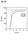
- the relative deflection becomes approximately equal to the input amplitude by making use of damping by a phase difference after the resonant point in a very small vibration region up to 1Hz, and by excitation caused by a leakage magnetic field in a region over 1Hz.
- the phase shift exceeds 150° , which is close to the anti-phase.
- the hardened spring characteristics having a spring constant of quasi-zero and soft non-linearity cause phase curves and relative deflection curves to move to a low-frequency region.
- the phase shift and relative deflection become large, and a state close to the anti-phase is created, thus reducing the vibration level.
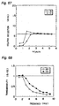
- the damping by disturbance cancellation exhibits a high vibration isolating performance throughout the entire frequency region, compared with the conventional viscous damping. As shown in Fig. 68, the vibration transmissibility is smaller than 1.0, resulting in non-resonance.
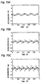
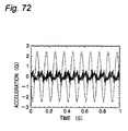
- Figs. 69A-69C, Figs. 70A-70C, Figs. 71A-71C, and Fig. 72 depict relationships between input acceleration and output acceleration when vibration having an amplitude of 12mm and a frequency of 1-10Hz has been input to the model YY. Even if the input acceleration varies, the output acceleration varies little and, hence, it can be seen that the model YY is superior in vibration absorption.
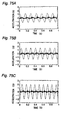
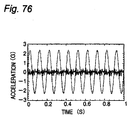
- Figs. 73A-73C, Figs. 74A-74C, Figs. 75A-75C, and Fig. 76 depict relationships between input acceleration and output acceleration when vibration having an amplitude of 12mm and a frequency of 1-10Hz has been input to the model XX.
- the vibration transmissibility of the model XX is smaller than that of the model YY.
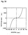
- Fig. 78 depicts non-linear characteristics obtained by setting the spring constant to be substantially zero with only a magneto-spring, as in the vibration mechanism M1 shown in Figs. 49 to 53 and the vibration mechanism M2 shown in Figs. 54 to 59.
- the magnetic energy accumulated between opposing repulsive magnets can be made constant by controlling the opposing area of and the distance between the magnets, i.e., by making the repulsive force given by Equation (2) constant, making it possible to obtain hardened non-linear spring characteristics.
- the relative deflection occurs in a low-frequency region, and improvement in vibration transmissibility is expected in the low-frequency region.
- the anti-phase after a resonant point provides a high vibration isolating performance in a low-frequency region.
- the way of thinking applied to vibrographs i.e., a method of utilizing a range in which ⁇ is sufficiently larger than ⁇ 0 in vibration isolation by reducing the natural frequency and a method of disturbance cancellation are both applied to a vibration isolating apparatus under passive control.
- Hardened spring characteristics have been designed wherein the spring constant is set to quasi-zero around the balanced or equilibrium point by controlling the geometric dimensions of the opposing magnets, and wherein there are provided non-linear spring characteristics in the direction towards the bottom end shock.
- the vibration isolating effects of such characteristics have been confirmed by analysis and vibration experiments in which a sine wave has been input. As a result, the following conclusions have been obtained.
Landscapes
- Engineering & Computer Science (AREA)
- General Engineering & Computer Science (AREA)
- Mechanical Engineering (AREA)
- Physics & Mathematics (AREA)
- Electromagnetism (AREA)
- Acoustics & Sound (AREA)
- Aviation & Aerospace Engineering (AREA)
- Vibration Prevention Devices (AREA)
- Control Of Position Or Direction (AREA)
- Reciprocating, Oscillating Or Vibrating Motors (AREA)
Applications Claiming Priority (2)
| Application Number | Priority Date | Filing Date | Title |
|---|---|---|---|
| JP14486099 | 1999-05-25 | ||
| JP11144860A JP2000337434A (ja) | 1999-05-25 | 1999-05-25 | 振動機構 |
Publications (3)
| Publication Number | Publication Date |
|---|---|
| EP1055838A2 true EP1055838A2 (fr) | 2000-11-29 |
| EP1055838A3 EP1055838A3 (fr) | 2001-05-30 |
| EP1055838B1 EP1055838B1 (fr) | 2005-07-13 |
Family
ID=15372093
Family Applications (1)
| Application Number | Title | Priority Date | Filing Date |
|---|---|---|---|
| EP00111162A Expired - Lifetime EP1055838B1 (fr) | 1999-05-25 | 2000-05-24 | Mécanisme vibratoire |
Country Status (7)
| Country | Link |
|---|---|
| US (1) | US6325365B1 (fr) |
| EP (1) | EP1055838B1 (fr) |
| JP (1) | JP2000337434A (fr) |
| KR (1) | KR100365897B1 (fr) |
| CN (1) | CN1139734C (fr) |
| DE (1) | DE60021229T2 (fr) |
| TW (1) | TW457341B (fr) |
Cited By (1)
| Publication number | Priority date | Publication date | Assignee | Title |
|---|---|---|---|---|
| RU2678932C1 (ru) * | 2017-12-22 | 2019-02-04 | Федеральное государственное бюджетное учреждение наук Институт проблем машиноведения Российской академии наук (ИПМаш РАН) | Способ гашения вибрации упругих элементов конструкций |
Families Citing this family (16)
| Publication number | Priority date | Publication date | Assignee | Title |
|---|---|---|---|---|
| JP4931305B2 (ja) * | 2000-10-30 | 2012-05-16 | 株式会社デルタツーリング | マグネットユニット |
| DE10220008A1 (de) * | 2002-05-03 | 2003-11-13 | Integrated Dynamics Eng Gmbh | Magnetische Federeinrichtung mit negativer Steifheit |
| KR100494805B1 (ko) * | 2003-07-30 | 2005-06-13 | 현대자동차주식회사 | 비대칭 가변강성을 갖는 차량용 마운트 장치 |
| WO2011065441A1 (fr) * | 2009-11-25 | 2011-06-03 | シンフォニアテクノロジー株式会社 | Dispositif d'amortissement de vibrations et véhicule comprenant celui-ci |
| EP2472139A1 (fr) * | 2011-01-03 | 2012-07-04 | Technische Universiteit Eindhoven | Isolateur de vibrations |
| CN102774300A (zh) * | 2011-05-08 | 2012-11-14 | 何新法 | 一种磁悬浮车辆坐椅凳抗震方法 |
| KR101279589B1 (ko) | 2011-05-26 | 2013-06-27 | 한국과학기술원 | 저항력 발생모듈, 이를 이용한 댐퍼장치, 전자제품, 휴대용기기, 저항력 발생방법, 및 그 기록매체 |
| JP6009905B2 (ja) * | 2012-10-26 | 2016-10-19 | Nok株式会社 | 回転変動吸収ダンパプーリ |
| US9188189B2 (en) | 2013-06-19 | 2015-11-17 | Honeywell International Inc. | Isolators including magnetically-assisted thermal compensation devices |
| CN104343873B (zh) * | 2014-08-29 | 2017-05-24 | 马忠威 | 永磁柔性阻尼组件 |
| US10208824B2 (en) * | 2015-06-03 | 2019-02-19 | Zachary Stein | Suspension assembly |
| CN109708386A (zh) * | 2018-08-07 | 2019-05-03 | 青岛海尔股份有限公司 | 压缩机承载装置及具有该压缩机承载装置的冰箱 |
| CN110007605B (zh) * | 2019-05-20 | 2020-03-24 | 长沙学院 | 一种排斥式磁悬浮装置的鲁棒预测控制方法 |
| WO2021078757A1 (fr) * | 2019-10-21 | 2021-04-29 | Koninklijke Philips N.V. | Système de suspension d'isolation acoustique |
| CN111795366A (zh) * | 2020-07-28 | 2020-10-20 | 张帮鑫 | 一种减震led射灯及其减震方法 |
| US11796022B1 (en) * | 2022-07-14 | 2023-10-24 | Ehoma Industrial Corporation | Magnetic levitation buffer device |
Family Cites Families (14)
| Publication number | Priority date | Publication date | Assignee | Title |
|---|---|---|---|---|
| DE13185C (de) | N. G. sörensen in Stockholm | Verfahren zum Schwarzfärben von Leder unter Anwendung von Vanadin-Verbindungen | ||
| DE2024746A1 (de) * | 1970-05-21 | 1971-12-02 | Kloeckner Werke Ag | Feder |
| DE3136320C2 (de) * | 1981-09-12 | 1983-10-20 | Deutsche Forschungs- und Versuchsanstalt für Luft- und Raumfahrt e.V., 5000 Köln | Verfahren und Vorrichtung zur Unterdrückung des Außenlast-Tragflügel-Flatterns von Flugzeugen |
| DE3431117C2 (de) * | 1984-08-24 | 1987-04-16 | Adam Opel AG, 6090 Rüsselsheim | Steuerbares elastisches Lager |
| DE3602599A1 (de) * | 1986-01-29 | 1987-07-30 | Bosch Gmbh Robert | Vorrichtung zur verstellung der federsteifigkeit einer magnetfeder |
| DE3817056A1 (de) * | 1988-05-19 | 1989-11-30 | Bosch Gmbh Robert | Magnetfeder |
| FR2668969B1 (fr) * | 1990-11-13 | 1993-02-05 | Braillon Cie | Coulisse a rappel magnetique. |
| US5542506A (en) * | 1991-12-03 | 1996-08-06 | University Of Houston-University Park | Magnet-superconductor systems for controlling and influencing relative motion |
| US5896961A (en) * | 1995-10-02 | 1999-04-27 | Kabushiki Kaisha Toshiba | Dynamic vibration absorber |
| CN1077966C (zh) * | 1996-04-08 | 2002-01-16 | 株式会社三角工具加工 | 具有阻尼特性的磁弹簧和具有所述磁弹簧的振动机构 |
| JPH1130274A (ja) * | 1997-05-15 | 1999-02-02 | Delta Tsuuring:Kk | 磁気バネを有する振動機構 |
| KR100281474B1 (ko) * | 1997-05-16 | 2001-02-01 | 후지타 히토시 | 자기스프링을구비한에너지출력기구 |
| NL1007127C2 (nl) * | 1997-09-26 | 1999-03-29 | Univ Delft Tech | Draagsysteem. |
| JP3115864B2 (ja) * | 1998-10-21 | 2000-12-11 | 株式会社デルタツーリング | 救急車用除振架台 |
-
1999
- 1999-05-25 JP JP11144860A patent/JP2000337434A/ja active Pending
-
2000
- 2000-05-24 DE DE60021229T patent/DE60021229T2/de not_active Expired - Fee Related
- 2000-05-24 US US09/577,139 patent/US6325365B1/en not_active Expired - Fee Related
- 2000-05-24 TW TW089110031A patent/TW457341B/zh active
- 2000-05-24 KR KR10-2000-0028051A patent/KR100365897B1/ko not_active Expired - Fee Related
- 2000-05-24 EP EP00111162A patent/EP1055838B1/fr not_active Expired - Lifetime
- 2000-05-25 CN CNB001176846A patent/CN1139734C/zh not_active Expired - Fee Related
Cited By (1)
| Publication number | Priority date | Publication date | Assignee | Title |
|---|---|---|---|---|
| RU2678932C1 (ru) * | 2017-12-22 | 2019-02-04 | Федеральное государственное бюджетное учреждение наук Институт проблем машиноведения Российской академии наук (ИПМаш РАН) | Способ гашения вибрации упругих элементов конструкций |
Also Published As
| Publication number | Publication date |
|---|---|
| US6325365B1 (en) | 2001-12-04 |
| CN1139734C (zh) | 2004-02-25 |
| KR20010049400A (ko) | 2001-06-15 |
| KR100365897B1 (ko) | 2003-02-06 |
| EP1055838A3 (fr) | 2001-05-30 |
| JP2000337434A (ja) | 2000-12-05 |
| DE60021229T2 (de) | 2006-05-24 |
| EP1055838B1 (fr) | 2005-07-13 |
| DE60021229D1 (de) | 2005-08-18 |
| TW457341B (en) | 2001-10-01 |
| CN1275686A (zh) | 2000-12-06 |
Similar Documents
| Publication | Publication Date | Title |
|---|---|---|
| EP1055838B1 (fr) | Mécanisme vibratoire | |
| EP0833074B1 (fr) | Ressort magnetique dote de caracteristiques d'amortissement et mecanisme vibratoire equipe de ce type de ressort | |
| US6585240B1 (en) | Vibration relief apparatus and magnetic damper mechanism therefor | |
| JP2000234649A (ja) | サスペンションユニット | |
| KR100331934B1 (ko) | 자기스프링을구비한진동기구 | |
| EP0995924B1 (fr) | Isolateur de vibrations avec ressorts magnétiques | |
| Wang et al. | Lever-type high-static-low-dynamic-stiffness vibration isolator with electromagnetic shunt damping | |
| JPH1086724A (ja) | 磁気浮上式サスペンションユニット | |
| JP3747112B2 (ja) | 減衰特性を有する磁気バネ | |
| JP3924596B2 (ja) | 負の減衰特性を有する磁性バネ振動機構 | |
| US12168375B1 (en) | Motion control system | |
| JP3924597B2 (ja) | 負の減衰特性を有する磁性バネ振動機構 | |
| JPH1086725A (ja) | 磁気浮上式サスペンションユニット | |
| JP3890383B2 (ja) | 減衰特性を有する磁性バネ | |
| JP3903163B2 (ja) | 磁気浮上式サスペンションユニット | |
| Fujita et al. | Vibration characteristics of vertical suspension using magneto-spring | |
| JPH1067267A (ja) | 磁気浮上式サスペンションユニット | |
| JP2008185184A (ja) | インホイールモータ用吸振機 | |
| JP2000193025A (ja) | 磁気回路 | |
| Todaka et al. | Moving simulation of vibration systems using permanent magnets | |
| Tohtake et al. | A103 Study on the Vibration Control by the Modal Analysis of a MAGLEV Vehicle |
Legal Events
| Date | Code | Title | Description |
|---|---|---|---|
| PUAI | Public reference made under article 153(3) epc to a published international application that has entered the european phase |
Free format text: ORIGINAL CODE: 0009012 |
|
| AK | Designated contracting states |
Kind code of ref document: A2 Designated state(s): DE FR GB |
|
| AX | Request for extension of the european patent |
Free format text: AL;LT;LV;MK;RO;SI |
|
| PUAL | Search report despatched |
Free format text: ORIGINAL CODE: 0009013 |
|
| AK | Designated contracting states |
Kind code of ref document: A3 Designated state(s): AT BE CH CY DE DK ES FI FR GB GR IE IT LI LU MC NL PT SE |
|
| AX | Request for extension of the european patent |
Free format text: AL;LT;LV;MK;RO;SI |
|
| 17P | Request for examination filed |
Effective date: 20011130 |
|
| AKX | Designation fees paid |
Free format text: DE FR GB |
|
| 17Q | First examination report despatched |
Effective date: 20031020 |
|
| GRAP | Despatch of communication of intention to grant a patent |
Free format text: ORIGINAL CODE: EPIDOSNIGR1 |
|
| GRAS | Grant fee paid |
Free format text: ORIGINAL CODE: EPIDOSNIGR3 |
|
| GRAA | (expected) grant |
Free format text: ORIGINAL CODE: 0009210 |
|
| AK | Designated contracting states |
Kind code of ref document: B1 Designated state(s): DE FR GB |
|
| REG | Reference to a national code |
Ref country code: GB Ref legal event code: FG4D |
|
| REF | Corresponds to: |
Ref document number: 60021229 Country of ref document: DE Date of ref document: 20050818 Kind code of ref document: P |
|
| ET | Fr: translation filed | ||
| PLBE | No opposition filed within time limit |
Free format text: ORIGINAL CODE: 0009261 |
|
| STAA | Information on the status of an ep patent application or granted ep patent |
Free format text: STATUS: NO OPPOSITION FILED WITHIN TIME LIMIT |
|
| 26N | No opposition filed |
Effective date: 20060418 |
|
| PGFP | Annual fee paid to national office [announced via postgrant information from national office to epo] |
Ref country code: DE Payment date: 20080530 Year of fee payment: 9 |
|
| PGFP | Annual fee paid to national office [announced via postgrant information from national office to epo] |
Ref country code: GB Payment date: 20080527 Year of fee payment: 9 |
|
| GBPC | Gb: european patent ceased through non-payment of renewal fee |
Effective date: 20090524 |
|
| REG | Reference to a national code |
Ref country code: FR Ref legal event code: ST Effective date: 20100129 |
|
| PG25 | Lapsed in a contracting state [announced via postgrant information from national office to epo] |
Ref country code: FR Free format text: LAPSE BECAUSE OF NON-PAYMENT OF DUE FEES Effective date: 20090602 |
|
| PGFP | Annual fee paid to national office [announced via postgrant information from national office to epo] |
Ref country code: FR Payment date: 20080422 Year of fee payment: 9 |
|
| PG25 | Lapsed in a contracting state [announced via postgrant information from national office to epo] |
Ref country code: GB Free format text: LAPSE BECAUSE OF NON-PAYMENT OF DUE FEES Effective date: 20090524 |
|
| PG25 | Lapsed in a contracting state [announced via postgrant information from national office to epo] |
Ref country code: DE Free format text: LAPSE BECAUSE OF NON-PAYMENT OF DUE FEES Effective date: 20091201 |