EP1055878A2 - Bougie à incandescence et son procédé de fabrication - Google Patents
Bougie à incandescence et son procédé de fabrication Download PDFInfo
- Publication number
- EP1055878A2 EP1055878A2 EP00110503A EP00110503A EP1055878A2 EP 1055878 A2 EP1055878 A2 EP 1055878A2 EP 00110503 A EP00110503 A EP 00110503A EP 00110503 A EP00110503 A EP 00110503A EP 1055878 A2 EP1055878 A2 EP 1055878A2
- Authority
- EP
- European Patent Office
- Prior art keywords
- resistor
- point
- winding axis
- spiral
- tube
- Prior art date
- Legal status (The legal status is an assumption and is not a legal conclusion. Google has not performed a legal analysis and makes no representation as to the accuracy of the status listed.)
- Granted
Links
Images


Classifications
-
- F—MECHANICAL ENGINEERING; LIGHTING; HEATING; WEAPONS; BLASTING
- F23—COMBUSTION APPARATUS; COMBUSTION PROCESSES
- F23Q—IGNITION; EXTINGUISHING-DEVICES
- F23Q7/00—Incandescent ignition; Igniters using electrically-produced heat, e.g. lighters for cigarettes; Electrically-heated glowing plugs
- F23Q7/001—Glowing plugs for internal-combustion engines
- F23Q2007/004—Manufacturing or assembling methods
Definitions
- the present invention relates to a glow plug for improving the startability of a diesel engine, or other devices, and a method for producing the same.
- a glow plug has been proposed, for example, in Japanese Unexamined Patent Publication (Kokai) No. 9-217933.
- This glow plug comprises a tube (sheath) and a resistor embedded in an insulating powder contained in the interior of the tube, wherein the resistor is wound in a spiral shape on a winding axis corresponding to a longitudinal axis of the tube.
- the resistor is energized with a current to generate heat.
- This glow plug is usually produced by placing the resistor in the tube and, after filling an insulating powder in the interior of the tube, swaging the tube to increase the filling density of the insulating powder.
- the resistor is subjected to a compressive force applied in the direction vertical to the axis on which the spiral is wound. Since the resistor is wound in a spiral shape about the longitudinal axis of the tube as described above, the resistor is compressed in the axial direction of resistor wire, whereby the resistor becomes thicker in diameter due to this compressive force to decrease its resistance. This is contradictory to the requirement in that the resistor must have a large resistance value to act as a heater.
- the present inventors have tried to solve this problem from the view point that the increase in diameter of the resistor due to swaging could be minimized by tilting the resistor relative to the winding axis of the spiral so that the wire axis of the resistor wound in a spiral shape largely deviates from the direction of the compressive force generated due to the swaging.
- Fig. 2(a) A distance between a first point t1 and a second point t2 measured in the direction of an axis M about which the resistor is wound defines a spiral pitch P. Note that the axis M is an imaginary line.
- a third point t3 is defined on the resistor J intermediate between the first and second points at a position apart half a length of the resistor between the first and second points from the first point.
- a distance Q between the third point and the first point measured in the winding direction is a so-called half spiral pitch which is 1/2 of the spiral pitch.
- a compressive force is applied to the resistor J in the direction vertical to the winding direction, which is generated due to the swaging, as shown in the arrowed direction R as shown in Fig. 2(a). Accordingly, the resistor J collapses in the wire-axial direction as shown in Fig. 2(b) to result in an increase in the wire diameter.
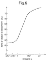
- the inventors have studied to find how spiral shape of the resistor should be tilted relative to the winding axis for purpose of properly restricting the variation in resistance of the resistor due to swaging. As a result, as shown in Fig. 6, it has been found that there is a certain inclination range of the resistor wherein the difference in resistance between before and after swaging is significantly minimized.
- the present invention is based on this knowledge.
- An object of the present invention is to provide a glow plug capable of restricting the resistance variation of a resistor caused by the swaging of a tube and a method of producing the same.
- a glow plug comprising a hollow tube (3) and a resistor (4, 5) retained in the tube while being wound in a spiral shape having a winding axis (M) coinciding with a longitudinal axis of the tube, the resistor being heated by being energized with a current, characterized in that a third point (t3) is defined at a position on the resistor between a first point (t1) and a second point (t2) defining a spiral pitch (P); the third point being distant from the first point and close to the second point (t2) at half the distance between the first point and the second point along the resistor; and in that the resistor is inclined relative to the winding axis so that a distance Q between the third point and the first point measured in the direction of the winding axis is 0.75 times the spiral pitch or more; the distance Q being the maximum value relative to the spiral pitch P as the tube turns 180 degrees on the winding axis (when an imaginary plane K of the resistor rotate
- a glow plug capable of properly restricting the resistance variation of the resistor (4, 5) due to the swaging of the tube (3) wherein the distance Q between the third point (t3) and the first point (t1) measured in the direction of the winding axis (M) is 0.75 times the spiral pitch (P) or more; the distance Q being the maximum value relative to the spiral pitch (P) as the tube (3) turns 180 degrees on the winding axis.
- the third point (t3) which defines half a pitch is alternatively defined as a point located in an imaginary plane (K) containing the first point (t1) and the winding axis (M) at a position opposite to the first point (t1) relative to the winding axis.
- Another aspect of the present invention employs the latter definition of the third point (t3), and it is possible to provide a glow plug, capable of properly restricting the resistance variation of the resistor (4, 5) due to the swaging of the tube (3), wherein the distance Q between the third point and the first point (t1) measured in the direction of the winding axis (M) is 0.75 times the spiral pitch (P) or more; the distance Q being the maximum value relative to the spiral pitch P as the tube (3) turns 180 degrees on the winding axis.
- the distance Q between the third point (t3) and the first point (t1) measured in the direction of the winding axis (M) is equal to the spiral pitch (P) or more (that is, one turn of the spiral pitch or more), it is possible to provide a glow plug capable of properly restricting the resistance variation of the resistor due to the swaging of the tube (3) at a higher level.
- the present invention also includes a method for producing a glow plug, mentioned in the preceding aspects, characterized in that the method comprises the steps of preparing a spiral body (100) of a wire material wound about a winding axis (M) to finally form the resistor (4, 5), supporting the circumference of the spiral body with a pair of split jigs (103, 104) arranged opposite to each other relative to the winding axis, pressing the spiral body by moving the pair of split jigs toward each other while translating the pair of split presser jigs in reverse to each other so that the spiral body is tilted relative to the winding axis, and after the spiral body is inserted into the tube (3), swaging the tube along the winding axis.
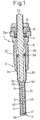
- a glow plug 1 shown in Fig. 1 according to the present invention is mounted to each of a plurality of (for example, four) cylinders (not shown) of a diesel engine for facilitating the ignition and combustion of fuel at a starting stage of the engine.
- the glow plug 1 includes a hollow housing 2 made of iron type material having a threaded portion 21 for the detachable mounting of the glow plug 1 to the cylinder.
- An elongate bottomed heater tube (referred to as a tube in this text) 3 with a blocked end 3a and an open end 3b opposite thereto is press-fitted into the housing 2 from one end 2a thereof.
- the heater tube 3 is made of electro-conductive material excellent in resistance to heat and oxidation (such as stainless steel) and is located so that the blocked end 3a is exposed from the one end 2a of the housing 2.
- the heater tube 3 has a smaller-diameter portion 31 on the one end side and a larger-diameter portion 32 on the other end side.
- the smaller-diameter portion 31 is formed by swaging the outer diameter of the tube.
- Coil-shaped first and second resistors (referred to as a resistor in this text) 4 and 5 are provided within the interior of the heater tube 3 along the longitudinal axis thereof.
- the first resistor 4 is built-in within the heater tube 3 closer to the blocked end 3b and the second resistor 5 is closer to the open end 3b.
- the first resistor 4 and the second resistor 5 are formed of a wire wound in a spiral shape about the longitudinal axis of the heater tube 3 while tilting relative to the winding axis, which spiral shape will be described in more detail later.
- One end 41 of the first resistor 4 is electrically connected to the blocked end 3a of the heater tube 3, while the other end 42 of the first resistor 4 is electrically connected to one end 51 of the second resistor 5.
- the other end 52 of the second resistor 5 is electrically connected by welding or others to one end 61 of an internal shaft 6 made of iron type material fixedly inserted into the housing 2.
- a portion of the internal shaft 6 closer to the one end 61, the first resistor 4 and the second resistor 5 are embedded in an insulating powder 30 of a heat-resistant and insulating material (such as magnesia) filled within the heater tube 3.
- a heat-resistant and insulating material such as magnesia
- the first resistor 4 is made of a first electro-conductive material (for example, iron-chromium alloy or nickel-chromium) having a small rate of change in resistivity (i.e., resistivity at 1000°C/resistivity at 20°C) between a normal temperature (20°C) and 1000°C (a temperature of the first resistor 4 of the glow plug 1 during preheating) such as approximately 1, while the second resistor 5 is made of a second electro-conductive material (for example, nickel, low-carbon steel or cobalt-iron alloy) having the rate of change defined above as large as 5 to 14.
- a first electro-conductive material for example, iron-chromium alloy or nickel-chromium
- resistivity at 1000°C/resistivity at 20°C between a normal temperature (20°C) and 1000°C (a temperature of the first resistor 4 of the glow plug 1 during preheating) such as approximately 1
- the second resistor 5 is made of a second electro-conductive material (for example, nickel, low-carbon steel or cobal
- the second electro-conductive material has a larger positive temperature coefficient of resistivity than the first electro-conductive material, wherein the temperature coefficient of resistivity is defined by a tangent of a graph obtained while plotting the measured resistance on the coordinates of which horizontal axis represents the temperature and of which vertical axis represents the resistance.
- a fused section 45 connecting the first resistor 4 with the second resistor 5 are formed between both the resistors 4 and 5 by a plasma arc-welding.
- the fused section 45 is formed by overlapping the other end 42 of the first resistor 4 with one end 51 of the second resistor 5 and applying a plasma arc to the overlapped portion.
- a portion of the internal shaft 6 closer to the one end 61 is inserted into the heater tube 3 through the open end 3b, while another portion of the internal shaft 6 closer to the other end 62 is fixedly secured to the other end 2b of the housing 2 in an insulated manner via an O-ring 7 made of electro-insulating material such as fluorine type rubber and a bush 8 made of resin by tightening a nut 9.
- this glow plug 1 it is possible to supply a large current to the first resistor 4 immediately after the initiation of power supply to heat the first resistor 4.
- the resistance of the second resistor 5 increases due to the temperature rise thereof, which in turn causes the power supply to the first resistor 4 to decrease.
- the first resistor 4 is prevented from breaking due to the excessive temperature rise.
- Fig. 2 illustrates a spiral shape of a resistor J of a conventional glow plug of a general type
- Figs. 3A and 3B illustrate a spiral shape of a resistor 4, 5 according to one embodiment of the present invention. Note the first and second resistors 4 and 5 of this embodiment have substantially the same spiral shape.
- the third point t3 on the resistor J is determined as a middle point of the length of the resistor J between the first point t1 and the second point t2, so that a measured length of the resistor J between the point t1 and the point t3 is equal to that between the point t2 and the point t3.
- the third point t3 may be defined as a point on an imaginary plane K (indicated by a broken line shown in Fig. 2) which starts from the first point t1 toward the point t2 along the resistor J to be positioned opposite to the first position relative to the winding axis M.
- the distance Q between the third point 3 and the first point t1 measured in the direction of the winding axis M is in a range from about 0.5 to about 0.74 times the spiral pitch P.
- a compressive force generated by the swaging is applied to the resistor J in the direction vertical to the winding axis as shown by an arrow R in Fig. 2.
- This compressive force causes the resistor J to collapse in the axial direction of the resistor wire to increase the wire diameter.
- the smaller the spiral pitch the larger the tendency of increase in wire diameter because the orientation of the resistor wire is closer to the vertical to the winding axis.
- the resistor 4, 5 of the present invention is of a spiral shape as shown in Figs. 3A and 3B.
- the example of Fig. 3A is of a clockwise (right-directional) spiral shape as seen in the z-direction (directed from bottom to top in the drawing) in the x, y, z orthogonal coordinates, while that of Fig. 3B is of a counterclockwise (left-directional) spiral as seen in the z-direction.
- the points t1, t2 and t3 the spiral pitch P, the distance Q, the imaginary winding axis M and the compressive force-application direction R are also defined in the same manner as in Fig. 2.
- the spiral shape is tilted in one direction relative to the winding axis M so that the distance Q is 0.75 times the spiral pitch P or more at a position wherein the distance Q becomes maximum relative to the spiral pitch P as the heater tube 3 turns 180 degrees on the winding axis M.
- the wire axis of the resistor 4, 5 is deflected from the direction R of the compressive force to a larger extent than in the prior art device.
- the resistor 4, 5 is tilted in the direction of the winding axis M to such an extent that the distance Q is larger than the spiral pitch P (Q > P) at the position of maximized distance Q and the third point t3 is outside a range from the point t1 to the point t2.
- the resistor 4, 5 of this embodiment is tilted relative to the winding axis M in one direction so that the distance Q is equal to 0.75 times the spiral pitch P or more.
- the resistor 4, 5 is tilted in the direction of the winding axis M to such an extent that the distance Q is larger than the spiral pitch P (Q > P) and the third point t3 is outside a range from the point t1 to the point t2.
- the distance Q is defined by using the imaginary plane K
- the spiral pitch P is larger for the purpose of preventing the wire diameter of the resistor 4, 5 from increasing, the spiral pitch P is selected to be equal to the coil diameter (2r) of the resistor 4, 5 or less in this embodiment.
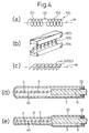
- Figs. 4(a) to 4(e) illustrate the steps of the method for the production.
- a spiral body 100 finally to be a first resistor 4 and a second resistor 5 welded to each other in a fused section 45 is prepared.
- This spiral body 100 consists of a wire piece 101 (finally to be the first resistor 4) and a wire piece 102 (finally to be the second resistor 5), both made of the same materials as those of the prior art resistors, connected to each other in the fused section 45 by plasma arc welding as described above.
- a pair of split jigs 103, 104 are used, which define an interior space corresponding to the circumferential shape of the spiral body 100 when fitted to each other.
- the split jigs 103, 104 are of a symmetrical shape and arranged opposite to each other while interposing the winding axis M between the both so that the circumference of the spiral body 100 is encircled and held thereby.
- the internal shaft 6 has been welded to the spiral body 100.
- the pair of split jigs 103, 104 holding the spiral body 100 between them are translated in reverse to each other along the winding axis M while being pressed in the mutual-approaching direction to tilt the spiral body 100 relative to the winding axis M.
- the resistor 4, 5 of the shape shown in Figs. 4(c), 3A and 3B is obtained.
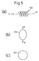
- the spiral body 100 has been prepared in advance to have an oval shape as seen in the direction of the winding axis M (the arrowed direction A in Fig. 5(a)) and is pressed by the pair of split jigs 103, 104 in the direction of the major diameter of the oval (the arrowed direction B in Fig. 5(b)), the oval shape is collapsed to nearly a circular shape as seen in the direction of the winding axis M as shown in Fig. 5(c).
- the resistor 4, 5 having such a shape is capable of generating heat generally uniformly around the same.
- the resistor 4, 5 and part of the internal shaft 6 are inserted into the heater tube 3. Then, a blocked end 3a is formed by fusing a tip end of the heater tube 3 together with the one end 41 of the first resistor 4 by a plasma arc, and the one end 41 of the first resistor 4 is electrically connected to the blocked end 3a. Thereafter, an insulating powder constituting the insulating powdery body 30 is filled in the heater tube 3 and sealed by the seal 33.
- the heater tube 3 is swaged in the direction of the winding axis M (the longitudinal direction of the heater tube 3) to increase the filling density of the powdery body 30 in the interior of the tube 3.
- the resistor 4, 5 held in the interior of the heater tube 3 is obtained.
- the resistor 4, 5 is tilted in one direction relative to the winding axis M for the purpose of properly restricting the resistance variation caused by a compressive force of the swaging, so that the distance Q at a position of maximized distance Q is 0.75 times the spiral pitch P or more.
- Fig. 6 is a graph showing the effect of the present invention, wherein a horizontal axis represents the distance Q at a position of maximized distance Q (a value standardized by the spiral pitch P) and a vertical axis represents the rate of change in resistivity (resistance (( ⁇ ) after swaging/resistance ( ⁇ ) before swaging). While the swaging rate (rate of change in tube diameter) is 25% in this embodiment, within a range of the swaging rate suitable for glow plugs according to the present invention, substantially the same tendency is observed.
- the glow plug 1 according to the embodiment of the present invention wherein the distance Q at a position of maximized distance Q is 0.75 times the spiral pitch P or more is effective for restricting the rate of change in resistivity of the resistor 4, 5 caused by the swaging of the heater tube 3 as compared with the conventional glow plug having the distance Q at a position of maximized distance Q of less than 0.75 times the spiral pitch P.
- the distance Q at a position of maximized distance Q is equal to the spiral pitch P or more, it is possible to significantly restrict the rate of change in resistivity of the resistor.
- the arrangement is simple in structure in that the resistor 4, 5 is merely tilted in one direction relative to the winding axis M without decreasing the number of spirals, and therefore is suitable for a glow plug necessitating a large resistance in the resistor 4, 5 (for example, to be used with 24V or 42V).
- the resistor may be one or three or more connected in series or parallel to each other.
- both of the resistors 4, 5 are tilted in one direction relative to the winding axis M in the above embodiment, one of them (for example, the first resistor 4) may solely be tilted or part thereof may be tilted so that the resistance in the tilted portion is prevented from decreasing.
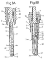
- Figs. 7A, 7B, 8A and 8B illustrate typical modifications described above.
- an outer diameter of the heater tube 3 is 5 mm, and there are no larger and smaller diameter portions.
- a wall thickness of the heater tube 3 is generally in a range from 0.3 mm to 1 mm, the wall thickness of glow plugs which have been produced since the 1960s.
- an outer diameter (coil diameter) of the resistor (coil heater) 4, 5 built-in within the heater tube 3 is selected so that a clearance between the resistor and the inner wall of the heater tube 3 (insulating clearance) of 0.1 mm or more is obtained to guarantee the insulation between the resistor 4, 5 and the heater tube 3. Therefore, the outer diameter of the resistor 4, 5 may be even a thinner diameter in a range from 2.5 mm to 4.8 mm as proposed in Japanese Unexamined Patent Publication No. 11-148647.
- the resistor 4 is a coil member made of one kind of material to have the same resistance value in the embodiment shown in Fig. 7A, a combination of several materials to have various resistance values may be adopted for the coil member, provided a tilting portion of two coils or more exists therein as defined in claims.
- the resistor 4 of the coil member located below the lower end surface of the housing 2 constitutes the above tilting portion.
- the diametrical cross-section of the coil wire is of an oval shape after the swaging because the formation of tilting portion.
- a major diameter of the oval shape is about 1.1 times an auxiliary diameter or more, for example, wherein the auxiliary diameter is in a range from 0.15 mm to 0.8 mm.
- An outer diameter of the resistor (coil diameter) may have a step difference of 0.05 mm or more provided an insulation clearance of 0.1 mm or more is guaranteed between the heater tube 3 and both the resistors 4, 5.
- a projected length of the heater tube 3 from the one end 2a of the housing 2 is, for example, in a range from 10 mm to 60 mm.
- the one end 61 of the internal shaft 6 may be located at any positions unless it is in contact with the end surface of the open end 3b of the heater tube 3. For instance, the one end 61 may be inserted 4 mm or more into the interior of the heater tube 3 and embedded in the insulating powder.
- a diameter of a portion of the internal shaft 6 closer to the one end 61 may be optional provided the insulating clearance of 0.1 mm or more is guaranteed from the inner wall of the heater tube 3; for example, the clearance might be in a range from 1 mm to 5.2 mm.
- a shape of the internal shaft 6 may be either stepless or multi-stepped as shown in Figs. 7B and 8A. The height difference between the steps is, for example, 0.05 mm or more.
- a trend in glow plug heaters is a heater tube 3 having a larger diameter portion 32 and a smaller diameter portion 31 as shown in Figs. 7B and 8A because thinner glow heaters are recently in demand.
- the larger diameter portion 31 and the smaller diameter portion 32 may be freely combined to each other; one example thereof is that the outer diameter of the smaller diameter portion 31 is in a range from 2.5 mm to 5.5 mm and that of the larger diameter portion 32 is in a range from 3 mm to 6 mm.
- a resistor 4, 5 housed therein may either a single coil member made of the same material having the same resistance value or a combination of coil members made of different materials having different resistance values, provided there is a tilting portion with two windings or more in part of the coil member.
- Figs. 7B and 8A The difference between the embodiments shown in Figs. 7B and 8A resides in that the one end 61 of the internal shaft 6 is positioned outside the housing 2 (Fig. 7B) or inside the same (Fig. 8A). Also, in Fig. 7B, the tilting portions are formed all over the first resistor 4 and part of the second resistor 5 closer to the other end 52 thereof, while remaining part of the second resistor 5 closer to the one end 51 thereof is not the tilting portion.
- the heater tube 3 is divided into two parts, one of which is housed in the housing 2 and other is projected out of the housing 2.
- the resistors 4, 5 are held in the respective parts while being embedded in the insulating powder 30. Both the resistors 4, 5 are electrically connected to each other via one part of the internal shaft 6 which is also divided into two parts.
- the resistor 5 in the housing 2 constitutes the tilting portion, and the dimensional relationship between the respective parts is the same as Fig. 7A.
- the above-mentioned dimensional relationship is also true of all glow plugs having resistors of a metallic wire (Fe, Cr, Ni, Co, Al, Pt or others) of a spiral shape in the heater tube.
- the present invention is also applicable to glow plugs which partly formed of ceramic material, provided metallic wires in a spiral shape exist.
- a resistor 4, 5 wound in a spiral shape is inserted into a hollow heater tube 3 while the winding axis M coincides with a longitudinal axis of the heater tube, and is held therein via an insulating powder 30, wherein the resistor 4, 5 is energized with a current to generate heat.
- a first point t1 and a second point t2 are determined on the resistor 4, 5 so that a spiral pitch P is defined between the both.
- a third point t3 is defined at a position on the resistor 4, 5 between the first point t1 and the second point t2 so that the third point t3 is distant from the first point t1 and near the second point t2 at half a length of the resistor 4, 5 between the first point t1 and the second point t2 along the resistor.
- the resistor 4, 5 is tilted relative to the winding axis M so that a distance Q between the third point t3 and the first point t1 measured in the direction of the winding axis M is 0.75 times the spiral pitch P or more wherein the distance Q is the maximum value relative to the spiral pitch (P) as the tube turns 180 degrees on the winding axis M.
Landscapes
- Engineering & Computer Science (AREA)
- Chemical & Material Sciences (AREA)
- Combustion & Propulsion (AREA)
- Mechanical Engineering (AREA)
- General Engineering & Computer Science (AREA)
- Resistance Heating (AREA)
Applications Claiming Priority (4)
| Application Number | Priority Date | Filing Date | Title |
|---|---|---|---|
| JP14881099 | 1999-05-27 | ||
| JP14881099 | 1999-05-27 | ||
| JP2000056057 | 2000-02-28 | ||
| JP2000056057A JP4092845B2 (ja) | 1999-05-27 | 2000-02-28 | グロープラグおよびその製造方法 |
Publications (3)
| Publication Number | Publication Date |
|---|---|
| EP1055878A2 true EP1055878A2 (fr) | 2000-11-29 |
| EP1055878A3 EP1055878A3 (fr) | 2005-03-02 |
| EP1055878B1 EP1055878B1 (fr) | 2007-10-03 |
Family
ID=26478884
Family Applications (1)
| Application Number | Title | Priority Date | Filing Date |
|---|---|---|---|
| EP20000110503 Expired - Lifetime EP1055878B1 (fr) | 1999-05-27 | 2000-05-17 | Bougie à incandescence et son procédé de fabrication |
Country Status (3)
| Country | Link |
|---|---|
| EP (1) | EP1055878B1 (fr) |
| JP (1) | JP4092845B2 (fr) |
| DE (1) | DE60036575T2 (fr) |
Cited By (2)
| Publication number | Priority date | Publication date | Assignee | Title |
|---|---|---|---|---|
| WO2003052323A1 (fr) * | 2001-12-18 | 2003-06-26 | Bosch Automotive Systems Corporation | Bougie de prechauffage pour moteur diesel et procede de fabrication de ladite bougie de prechauffage |
| EP2840313A4 (fr) * | 2012-04-20 | 2015-04-22 | Ngk Spark Plug Co | Bougie à incandescence |
Families Citing this family (1)
| Publication number | Priority date | Publication date | Assignee | Title |
|---|---|---|---|---|
| EP1406046B1 (fr) | 2001-06-19 | 2014-12-31 | NGK Spark Plug Co., Ltd. | Bougie de prechauffage et procede de fabrication d'une bougie de prechauffage |
Citations (1)
| Publication number | Priority date | Publication date | Assignee | Title |
|---|---|---|---|---|
| JPH09217933A (ja) | 1997-03-10 | 1997-08-19 | Jidosha Kiki Co Ltd | 自己温度制御型グロープラグ |
Family Cites Families (2)
| Publication number | Priority date | Publication date | Assignee | Title |
|---|---|---|---|---|
| CH378096A (it) * | 1960-06-28 | 1964-05-31 | Magneti Marelli Spa | Candela ad incandescenza munita di resistenza corazzata |
| IT1258675B (it) * | 1992-12-18 | 1996-02-27 | Candela ad incandescanza con doppia spirale di controllo per motori diesel |
-
2000
- 2000-02-28 JP JP2000056057A patent/JP4092845B2/ja not_active Expired - Fee Related
- 2000-05-17 DE DE2000636575 patent/DE60036575T2/de not_active Expired - Lifetime
- 2000-05-17 EP EP20000110503 patent/EP1055878B1/fr not_active Expired - Lifetime
Patent Citations (1)
| Publication number | Priority date | Publication date | Assignee | Title |
|---|---|---|---|---|
| JPH09217933A (ja) | 1997-03-10 | 1997-08-19 | Jidosha Kiki Co Ltd | 自己温度制御型グロープラグ |
Cited By (2)
| Publication number | Priority date | Publication date | Assignee | Title |
|---|---|---|---|---|
| WO2003052323A1 (fr) * | 2001-12-18 | 2003-06-26 | Bosch Automotive Systems Corporation | Bougie de prechauffage pour moteur diesel et procede de fabrication de ladite bougie de prechauffage |
| EP2840313A4 (fr) * | 2012-04-20 | 2015-04-22 | Ngk Spark Plug Co | Bougie à incandescence |
Also Published As
| Publication number | Publication date |
|---|---|
| DE60036575D1 (de) | 2007-11-15 |
| EP1055878A3 (fr) | 2005-03-02 |
| EP1055878B1 (fr) | 2007-10-03 |
| DE60036575T2 (de) | 2008-06-26 |
| JP2001041452A (ja) | 2001-02-13 |
| JP4092845B2 (ja) | 2008-05-28 |
Similar Documents
| Publication | Publication Date | Title |
|---|---|---|
| JP4288850B2 (ja) | グロープラグの製造方法 | |
| US4502430A (en) | Ceramic heater | |
| US6037568A (en) | Glow plug for diesel engine with ptc control element disposed in small-diameter sheath section and connected to the distal end thereof | |
| US4476378A (en) | Glow plug for use in diesel engine | |
| US4549071A (en) | Glow plug for use in diesel engine | |
| US4211204A (en) | Glow plug arrangement | |
| US6878903B2 (en) | Glow plug | |
| JPH0339212B2 (fr) | ||
| US5251589A (en) | Hot tip glow plug and method for making | |
| US5468933A (en) | Rod flame glow plug having a CoFe alloy regulating coil and a housing having a fuel connection for a metering device | |
| JPH04138550U (ja) | 自己温度制御型グロープラグ | |
| EP1055878B1 (fr) | Bougie à incandescence et son procédé de fabrication | |
| JP2002195559A (ja) | セラミックスヒータ型グロープラグおよびその製造方法。 | |
| EP1239222B2 (fr) | Dispositif chauffant céramique, et méthode de fabrication | |
| EP0365258A1 (fr) | Bougie à incandescence | |
| JP3560753B2 (ja) | ディーゼルエンジン用グロープラグ | |
| US20020125238A1 (en) | Glow plug for internal-combustion engines | |
| JP2015014393A (ja) | グロープラグの製造方法 | |
| JPH10110953A (ja) | グロープラグ | |
| US4641612A (en) | Electric starting aid for an internal combustion engine | |
| EP1243858B1 (fr) | Bougie à incandescence pour mesurer le courant d'ionisation d'un moteur | |
| JPH0155369B2 (fr) | ||
| JPS6350606Y2 (fr) | ||
| JP3028409B2 (ja) | 自己温度制御型グロープラグ | |
| JPS6335246Y2 (fr) |
Legal Events
| Date | Code | Title | Description |
|---|---|---|---|
| PUAI | Public reference made under article 153(3) epc to a published international application that has entered the european phase |
Free format text: ORIGINAL CODE: 0009012 |
|
| AK | Designated contracting states |
Kind code of ref document: A2 Designated state(s): AT BE CH CY DE DK ES FI FR GB GR IE IT LI LU MC NL PT SE |
|
| AX | Request for extension of the european patent |
Free format text: AL;LT;LV;MK;RO;SI |
|
| PUAL | Search report despatched |
Free format text: ORIGINAL CODE: 0009013 |
|
| AK | Designated contracting states |
Kind code of ref document: A3 Designated state(s): AT BE CH CY DE DK ES FI FR GB GR IE IT LI LU MC NL PT SE |
|
| AX | Request for extension of the european patent |
Extension state: AL LT LV MK RO SI |
|
| 17P | Request for examination filed |
Effective date: 20050704 |
|
| AKX | Designation fees paid |
Designated state(s): DE FR GB |
|
| 17Q | First examination report despatched |
Effective date: 20060912 |
|
| GRAP | Despatch of communication of intention to grant a patent |
Free format text: ORIGINAL CODE: EPIDOSNIGR1 |
|
| GRAS | Grant fee paid |
Free format text: ORIGINAL CODE: EPIDOSNIGR3 |
|
| GRAA | (expected) grant |
Free format text: ORIGINAL CODE: 0009210 |
|
| AK | Designated contracting states |
Kind code of ref document: B1 Designated state(s): DE FR GB |
|
| REG | Reference to a national code |
Ref country code: GB Ref legal event code: FG4D |
|
| REF | Corresponds to: |
Ref document number: 60036575 Country of ref document: DE Date of ref document: 20071115 Kind code of ref document: P |
|
| ET | Fr: translation filed | ||
| REG | Reference to a national code |
Ref country code: GB Ref legal event code: 746 Effective date: 20080603 |
|
| PLBE | No opposition filed within time limit |
Free format text: ORIGINAL CODE: 0009261 |
|
| STAA | Information on the status of an ep patent application or granted ep patent |
Free format text: STATUS: NO OPPOSITION FILED WITHIN TIME LIMIT |
|
| 26N | No opposition filed |
Effective date: 20080704 |
|
| PGFP | Annual fee paid to national office [announced via postgrant information from national office to epo] |
Ref country code: GB Payment date: 20100329 Year of fee payment: 11 |
|
| PGFP | Annual fee paid to national office [announced via postgrant information from national office to epo] |
Ref country code: FR Payment date: 20100525 Year of fee payment: 11 |
|
| PGFP | Annual fee paid to national office [announced via postgrant information from national office to epo] |
Ref country code: DE Payment date: 20100512 Year of fee payment: 11 |
|
| REG | Reference to a national code |
Ref country code: DE Ref legal event code: R119 Ref document number: 60036575 Country of ref document: DE |
|
| REG | Reference to a national code |
Ref country code: DE Ref legal event code: R119 Ref document number: 60036575 Country of ref document: DE |
|
| GBPC | Gb: european patent ceased through non-payment of renewal fee |
Effective date: 20110517 |
|
| REG | Reference to a national code |
Ref country code: FR Ref legal event code: ST Effective date: 20120131 |
|
| PG25 | Lapsed in a contracting state [announced via postgrant information from national office to epo] |
Ref country code: FR Free format text: LAPSE BECAUSE OF NON-PAYMENT OF DUE FEES Effective date: 20110531 |
|
| PG25 | Lapsed in a contracting state [announced via postgrant information from national office to epo] |
Ref country code: GB Free format text: LAPSE BECAUSE OF NON-PAYMENT OF DUE FEES Effective date: 20110517 |
|
| PG25 | Lapsed in a contracting state [announced via postgrant information from national office to epo] |
Ref country code: DE Free format text: LAPSE BECAUSE OF NON-PAYMENT OF DUE FEES Effective date: 20111130 |