EP1055974A2 - Séparation automatique d'un module de développement - Google Patents
Séparation automatique d'un module de développement Download PDFInfo
- Publication number
- EP1055974A2 EP1055974A2 EP00304113A EP00304113A EP1055974A2 EP 1055974 A2 EP1055974 A2 EP 1055974A2 EP 00304113 A EP00304113 A EP 00304113A EP 00304113 A EP00304113 A EP 00304113A EP 1055974 A2 EP1055974 A2 EP 1055974A2
- Authority
- EP
- European Patent Office
- Prior art keywords
- printing machine
- cover
- module
- machine
- door
- Prior art date
- Legal status (The legal status is an assumption and is not a legal conclusion. Google has not performed a legal analysis and makes no representation as to the accuracy of the status listed.)
- Granted
Links
- 239000002245 particle Substances 0.000 claims description 2
- 238000000034 method Methods 0.000 description 28
- 239000004793 Polystyrene Substances 0.000 description 8
- 239000000758 substrate Substances 0.000 description 7
- 108091008695 photoreceptors Proteins 0.000 description 6
- 239000000463 material Substances 0.000 description 5
- 239000004033 plastic Substances 0.000 description 5
- 229920003023 plastic Polymers 0.000 description 5
- 238000003384 imaging method Methods 0.000 description 4
- 239000007787 solid Substances 0.000 description 4
- 239000002699 waste material Substances 0.000 description 4
- 238000004140 cleaning Methods 0.000 description 3
- -1 for example Polymers 0.000 description 2
- 229920005669 high impact polystyrene Polymers 0.000 description 2
- 239000004797 high-impact polystyrene Substances 0.000 description 2
- 239000002184 metal Substances 0.000 description 2
- 239000004743 Polypropylene Substances 0.000 description 1
- 230000008878 coupling Effects 0.000 description 1
- 238000010168 coupling process Methods 0.000 description 1
- 238000005859 coupling reaction Methods 0.000 description 1
- 239000000428 dust Substances 0.000 description 1
- 229920002457 flexible plastic Polymers 0.000 description 1
- 238000009434 installation Methods 0.000 description 1
- 230000013011 mating Effects 0.000 description 1
- 229920001155 polypropylene Polymers 0.000 description 1
- 238000000926 separation method Methods 0.000 description 1
- 238000003466 welding Methods 0.000 description 1
- 230000003245 working effect Effects 0.000 description 1
Images


Classifications
-
- G—PHYSICS
- G03—PHOTOGRAPHY; CINEMATOGRAPHY; ANALOGOUS TECHNIQUES USING WAVES OTHER THAN OPTICAL WAVES; ELECTROGRAPHY; HOLOGRAPHY
- G03G—ELECTROGRAPHY; ELECTROPHOTOGRAPHY; MAGNETOGRAPHY
- G03G15/00—Apparatus for electrographic processes using a charge pattern
- G03G15/06—Apparatus for electrographic processes using a charge pattern for developing
- G03G15/08—Apparatus for electrographic processes using a charge pattern for developing using a solid developer, e.g. powder developer
- G03G15/0896—Arrangements or disposition of the complete developer unit or parts thereof not provided for by groups G03G15/08 - G03G15/0894
-
- G—PHYSICS
- G03—PHOTOGRAPHY; CINEMATOGRAPHY; ANALOGOUS TECHNIQUES USING WAVES OTHER THAN OPTICAL WAVES; ELECTROGRAPHY; HOLOGRAPHY
- G03G—ELECTROGRAPHY; ELECTROPHOTOGRAPHY; MAGNETOGRAPHY
- G03G21/00—Arrangements not provided for by groups G03G13/00 - G03G19/00, e.g. cleaning, elimination of residual charge
- G03G21/16—Mechanical means for facilitating the maintenance of the apparatus, e.g. modular arrangements
- G03G21/18—Mechanical means for facilitating the maintenance of the apparatus, e.g. modular arrangements using a processing cartridge, whereby the process cartridge comprises at least two image processing means in a single unit
- G03G21/1839—Means for handling the process cartridge in the apparatus body
- G03G21/1842—Means for handling the process cartridge in the apparatus body for guiding and mounting the process cartridge, positioning, alignment, locks
- G03G21/1853—Means for handling the process cartridge in the apparatus body for guiding and mounting the process cartridge, positioning, alignment, locks the process cartridge being mounted perpendicular to the axis of the photosensitive member
-
- G—PHYSICS
- G03—PHOTOGRAPHY; CINEMATOGRAPHY; ANALOGOUS TECHNIQUES USING WAVES OTHER THAN OPTICAL WAVES; ELECTROGRAPHY; HOLOGRAPHY
- G03G—ELECTROGRAPHY; ELECTROPHOTOGRAPHY; MAGNETOGRAPHY
- G03G2221/00—Processes not provided for by group G03G2215/00, e.g. cleaning or residual charge elimination
- G03G2221/16—Mechanical means for facilitating the maintenance of the apparatus, e.g. modular arrangements and complete machine concepts
- G03G2221/163—Mechanical means for facilitating the maintenance of the apparatus, e.g. modular arrangements and complete machine concepts for the developer unit
-
- G—PHYSICS
- G03—PHOTOGRAPHY; CINEMATOGRAPHY; ANALOGOUS TECHNIQUES USING WAVES OTHER THAN OPTICAL WAVES; ELECTROGRAPHY; HOLOGRAPHY
- G03G—ELECTROGRAPHY; ELECTROPHOTOGRAPHY; MAGNETOGRAPHY
- G03G2221/00—Processes not provided for by group G03G2215/00, e.g. cleaning or residual charge elimination
- G03G2221/16—Mechanical means for facilitating the maintenance of the apparatus, e.g. modular arrangements and complete machine concepts
- G03G2221/1678—Frame structures
- G03G2221/169—Structural door designs
Definitions
- This invention relates to electrostatographic reproduction machines, and more particularly to a process cartridge for use in electrostatographic reproduction machines. Specifically this invention relates to such a cartridge with automatic camming of a developer module.
- the process of electrostatographic reproduction includes charging a photo-conductive member to a substantially uniform potential so as to sensitize the surface thereof.
- a charged portion of the photoconductive surface is exposed at an exposure station to a light image of an original document to be reproduced.
- an original document to be reproduced is placed in registration, either manually or by means of an automatic document handler, on a platen for such exposure.
- CRU customer or user replaceable unit
- CRUs Customer replaceable units
- cartridges i.e., process cartridges
- the removal of the CRU and the replacement with a new CRU is intended to be a simple, easy task.
- CRU is replaced by first opening a cover or door and then sliding the CRU out of a cradle or location where the CRU fits within the machine.
- CRUs are used to interact with the xerographic process and with the paper within the machine. Therefore, CRUs frequently need to be engaged into an operating position within the machine during the installation of the CRU.
- the CRU thus typically is slid or placed into the opening where it fits and then positioned into an operating arrangement within the printing machine.
- the used CRU must first be separated from the components with which it engages and then withdrawn from the printing machine.
- a new replacement CRU must first be inserted into the machine and then interconnected with the operating portions of the printing machine.
- Such a typical CRU is in the form of a process cartridge.
- cranks and levers or knobs are typically used to separate the photoconductive drum from the developer roll within the process cartridge prior to the removal of the process cartridge.
- the current use of a lever or knob has at least two significant disadvantages. The first of these is that if the lever or knob fails to be properly utilized, the drum may be damaged by the removal of the process cartridge.
- An additional problem is that the operation of the lever or knob to separate the process cartridge from the drum makes the process cartridge change more time consuming, more difficult, and may require a trained operator to replace.
- the present invention is intended to alleviate at such problems.
- a mechanism for use in a printing machine having a cover for covering a portion of the printing machine.
- the mechanism is operably associated with the cover and with the portion of the printing machine.
- the mechanism is adapted so as to move the portion of the printing machine as the cover is opened.
- a development unit for use in a printing machine having a cover for covering a portion of the development unit.
- the development unit includes a development housing movably mounted to the printing machine and a member.
- the member is movably mounted to the development housing for advancing the marking particles toward the latent image.
- the development unit also includes a mechanism which is operably associated with the development housing and the cover so that said member moves away from the latent image as the cover is opened.
- a printing machine having a cover for covering a portion of the printing machine.
- the printing machine includes a mechanism operably associated with the cover and with the portion of the printing machine.
- the mechanism is adapted so as to move the portion of the printing machine as the cover is opened.
- a mechanism for use in a printing machine includes a first member defining a first member surface and a second member.
- the second member is operably associated with the first member, the second member defines a second member surface.
- the first member moves away from the second member when the first member surface slides with respect to the second member surface in a first direction.
- the first member moves toward the second member when the first member surface slides with respect to the second member surface in a second direction opposed to the first direction.
- the compact machine 20 may be frameless, meaning that it does not have a separate machine frame to which electrostatographic process subsystems are assembled, aligned to the frame, and then aligned relative to one another as is typically the case in conventional machines.
- the architecture of the compact machine 20 may include a number of individually framed, and mutually aligning machine modules that variously include pre-aligned electrostatographic active process subsystems.
- the frameless machine 20 may include a framed copy sheet input module (CIM) 22.
- the machine 20 includes a pair of copy sheet input modules, a main or primary module the CIM 22, and an auxiliary module the (ACIM) 24, each of which has a set of legs 23 that can support the machine 20 on a surface, therefore suitably enabling each CIM 22, 24 to form a base of the machine 20.
- each copy sheet input module (CIM, ACIM) includes a module frame 26 and a copy sheet stacking and lifting cassette tray assembly 28 that is slidably movable in and out relative to the module frame 26.
- the machine 20 includes two copy sheet input modules, the very base module is considered the auxiliary module (the ACIM), and the top module which mounts and mutually aligns against the base module is considered the primary module (the CIM).
- the machine 20 next includes a framed electronic control and power supply (ECS/PS) module 30, that as shown mounts onto, and is mutually aligned against the CIM 22 (which preferably is the top or only copy sheet input module).
- a framed latent image forming imager module 32 then mounts over and is mutually aligned against the ECS/PS module.
- the ECS/PS module 30 includes all controls and power supplies (not shown) for all the modules and processes of the machine 20. It also includes an image processing pipeline unit (IPP) 34 for managing and processing raw digitized images from a Raster Input Scanner (RIS) 36, and generating processed digitized images for a Raster Output Scanner (ROS) 38.
- IPP image processing pipeline unit
- the ECS/PS module 30 also includes harnessless interconnect boards and inter-module connectors (not shown), that provide all power and logic paths to the rest of the machine modules.
- An interconnect board (PWB) (not shown) connects the ECS controller and power supply boards (not shown) to the inter-module connectors, as well as locates all of the connectors to the other modules in such a manner that their mating connectors would automatically plug into the ECS/PS module during the final assembly of the machine 20.
- the ECS/PS module 30 may include a module frame 40 to which the active components of the module as above are mounted, and which forms a covered portion of the machine 20, as well as locates, mutually aligns, and mounts to adjacent framed modules, such as the CIM 22 and the imager module 32.
- the machine 20 may include a process cartridge module 44 that is insertably and removably mounted within the cavity 42, and in which it is mutually aligned with, and operatively connected to, the framed CIM, ECS/PS and imager modules 22, 30, 32.
- the machine 20 may include a framed fuser module 46, that is mounted above the process cartridge module 44, as well as adjacent an end of the imager module 32.
- the fuser module 46 includes a pair of fuser rolls 48, 50, and at least an exit roll 52 for moving an image carrying sheet through, and out of, the fuser module 46 into an output or exit tray 54.
- the fuser module also includes a heater lamp 56, temperature sensing means (not shown), paper path handling baffles (not shown), and a module frame 58 to which the active components of the module, as above, are mounted, and which forms a covered portion of the machine 20, as well as locates, mutually aligns, and mounts to adjacent framed modules, such as the imager module 32 and the process cartridge module 44.
- the machine 20 may include active components including a bypass feeder assembly 64, sheet registration rolls 66, toner image transfer and detack devices 68, and the fused image output or exit tray 54.
- the machine 20 may include drive coupling components and electrical connectors (not shown), and a module frame 70 to which the active components are mounted, and which forms a covered portion of the machine 20, as well as, locates, mutually aligns, and mounts to adjacent framed modules, such as the CIM 22, the process cartridge module 44, and the fuser module 46.
- the CRU or process cartridge module 44 may optionally include a photoreceptor subassembly 74, a charging subassembly 76, developer housing 100 including a source of fresh developer material, a cleaning subassembly 80 for removing residual toner as waste toner from a surface of the photoreceptor, and a waste toner sump subassembly 82 for storing waste toner.
- the process cartridge module 44 importantly provides and includes supporting, locating and aligning structures, as well as driving components for the process cartridge module 44.
- an imaging cycle of the machine 20 using the process cartridge module 44 can be briefly described as follows. Initially, a photoreceptor in the form of a photo-conductive drum 84 of the customer replaceable unit (CRU) or process cartridge module 44, rotating in the direction of the arrow 86, is charged by the charging subassembly 76. The charged portion of the drum is then transported to an imaging/exposing light 88 from the ROS 38 which forms a latent image on the drum 84, corresponding to an image of a document positioned on a platen 90, via the imager module 32. It will also be understood that the imager module 32 can easily be changed from a digital scanning module to a light lens imaging module.
- CRU customer replaceable unit
- the portion of the drum 84 bearing a latent image is then rotated to the developer housing 100 where the latent image is developed with developer material such as with charged single component magnetic toner using a magnetic developer roller 92 of the process cartridge module 44.
- the developed image on the drum 84 is then rotated to a near vertical transfer point 94 where the toner image is transferred to a copy sheet substrate 96 fed from the CIM 22 or ACIM 22 along a copy sheet or substrate path 98.
- the detack device 68 of the door module 60 is provided for charging the back of the copy sheet substrate (not shown) at the transfer point 94, in order to attract the charged toner image from the photoconductive drum 84 onto the copy sheet substrate.
- the copy sheet substrate with the transferred toner image thereon is then directed to the fuser module 46, where the heated fuser roll 48 and pressure roll 50 rotatably cooperate to heat, fuse and fix the toner image onto the copy sheet substrate.
- the copy sheet substrate then, as is well known, may be selectively transported to the output tray 54 or to another post-fusing operation.
- the portion of the drum 84 from which the developed toner image was transferred is then advanced to the cleaning subassembly 80 where residual toner and residual charge on the drum 84 are removed therefrom.
- the imaging cycle of the machine 20 using the drum 84 can then be repeated for forming and transferring another toner image as the cleaned portion again comes under the charging subassembly 76.
- the process cartridge module 44 includes a module housing 100 having a first side wall 102, a second and opposite side wall 104, a top wall 106 including a substantially horizontal portion 108 and a nearly vertical portion 110 defining a raised rear end 112 (rear as considered relative to the process cartridge 44 being inserted into the cavity 42). There is no rear wall, thus resulting in an open rear end 114 for mounting the photoreceptor subassembly 74.
- the trough shaped module housing also includes a front end wall 116 that connects at an angle to the top wall 106.
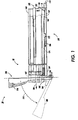
- mechanism 144 according to the present invention is shown.
- the mechanism 144 shown in Figure 3 is used in the printing machine 20.
- the printing machine 20 includes a cover 146 for providing access to the mechanism 144 when opened and to provide protection from dust and to prevent inadvertent access to the internal workings of the printing machine 20.
- the cover 146 may for example be in the form of a removable cover or in the form of a portion of a drawer which may be slid outwardly from the machine 20.
- the cover 146 is in the form of a door which as shown in Figure 4 is hinged about hinges 150 connecting lower end 152 of the cover 146 to the frame 154 of the printing machine 20.
- the cover 146 is utilized to cover a portion of the printing machine.
- the cover 146 is utilized to cover the developer unit 44.
- the mechanism 144 is operably associated with the cover 146 and may be directly or indirectly interconnected with each other. Further, the mechanism 144 is operably associated with portion 44 of the printing machine 20, for example developer unit 44. For example, the mechanism 144 may be directly or indirectly connected to the developer unit 44. The mechanism 144 is adapted so as to move the developer unit 44 of the printing machine 20 as the cover 146 is opened.
- the mechanism 144 may cooperate with the developer unit 44 to move the developer unit 44 in any direction which is advantageous for the removal of the developer unit 44 of the printing machine 20, for example, and as shown in Figure 3, the developer unit 44 may be pivotally connected to the printing machine by pivot point 156.
- the mechanism 144 is utilized to move the developer unit 44 from first position 160 to second position 162. While as shown in Figure 5 the mechanism 144 is used to rotate the developer unit 44, it should be appreciated that the mechanism 146 may be utilized to move the developer unit 44 in any desired direction.
- the mechanism 144 is shown utilized for moving the developer unit 44.
- the mechanism 144 as shown in Figure 5 includes a first member 164.
- the mechanism 144 also includes a second member 166 which is connected to the first member 164.
- the second member 166 is further connected to the developer unit 44.
- the second member 166 is connected to the cover 146.
- the first member 164 and the second member 166 are thus adapted so as to move the developer unit 44 of the printing machine 20 as the cover 146 is opened.
- the mechanism 144 is utilized to rotate the developer housing 100 about pivot point 156 from first position 160 as shown in solid to second position 162 as shown in phantom.
- the magnetic roller 92 is spaced a distance D from the photoconductive surface 170 of the photoreceptor drum 84.
- the distance D may be as little as 0.05 inches (1.3 mm) to as much as one inch (25 mm) or more with a distance D of around 0.1 to 0.3 inches (2.5 to 7.5 mm) being preferred.
- mechanism 144 may have any suitable shape and may for example be in the form of a linkage includes levers or be in the form of an electromechanical device such as a motor or solenoid, preferably and for simplicity, as shown in Figure 1, the second member 166 is in slidable contact with the first member 164 of the mechanism 144.
- the first member 164 of the mechanism 144 includes a first member surface 172.
- the second member 166 preferably includes a second member surface 174.
- the second member surface 174 is preferably in sliding contact with the first member surface 172 of the first member 164.
- the first member 164 is fixedly secured to the printing machine 20.
- the first member 164 may be fixedly secured to frame 154. It should be appreciated however, that the first member 164 may be integral to the frame 154.
- the second member 166 is preferably secured to the door 146.
- the second member 166 is preferably positioned between the first member 164 and the developer housing 100.
- the second member 166 is utilized to separate the developer housing 100 from the first member 164 as the door 146 is opened.
- the door 146 is first rotated downwardly in the direction of arrow 175 such that the door moves from door first position 176 shown in solid to door opened position 180 shown in phantom.
- the second member 166 may be connected to the door 146 in any suitable fashion.
- the second member 166 may include a connecting member (not shown) which is positioned between the door 146 and the second member 166. As shown in Figure 1, the second member 166 is directly connected to the door 146.
- the second member 166 may be connected to the door 146 in any suitable fashion.
- the second member 166 may be pivotally connected to the door 146. A pivotal connection of the second member 166 to the door 146 may permit the use of a solid rigid second member.
- the second member 166 may be fixedly connected to the door 146.
- the second member 166 may be connected to the door 146 by fasteners, by welding, or as shown in Figure 1, be glued to the door 146.
- the second member 166 may be pliable or flexible and may include restricted areas with reduced cross section for example, living hinges 182.
- the living hinges 182 permit the portion of the second member 166 directly connected to the door 146 to rotate with the door while permitting the portion of the second member 166 which is in contact with the first member 164 to move in a linear direction.
- the portion of the second member 166 attached to the door 146 moves in the direction of arrow 184.
- the second member surface 174 moves in the direction of arrow 186 in sliding contact with the first member surface 172.
- the movement of the second member surface 174 along arrow 186 causes upper surface 190 of the second member 166 to move upwardly in the direction of arrow 192.
- the movement of upper surface 190 in the direction of arrow 192 causes the developer housing 100 to move from first position 160 shown in solid, to second position 162 shown in phantom.
- the second member 166 causes the developer housing 100 to rotate to the second position 162 causing the magnetic roller 92 to separate from the photoconductive drum 84 permitting the easy removal of the developer housing 100 from the printing machine 20.
- the distance MP from the pivot point 156 to the second member 166, the angle a between the upper surface 190 of the second member 166 and the line between the pivot point 156 and the second member 166, the distance DP from the pivot point 156 to the transfer point 94, as well as, the vertical movement DM of the second member 166 affect the distance D that the magnetic roller 92 moves away from the photoconductive drum 84.
- the second member surface 174 forms an angle b between the upper surface 190 of the second member 166 and the second member surface 174.
- the angle b is chosen to provide for sufficient movement of the developer housing 100 in the direction of arrow 192.
- the angle b can be 10 degrees to 60 degrees with approximately 30 degrees being preferred.
- a motion of the second member 166 in the direction of arrow 184 of one inch (25 mm) will represent a motion of the second member 166 in the direction of arrow 92 of approximately 0.577 inches (14.7 mm).
- the first member 164 may be made of any suitable, durable material.
- the first member 164 may be a plastic or a metal.
- the first member 164 may be integral with another part of the printing machine 20, i.e. the frame 154. If the frame 154 is made of a plastic for example, the frame 154 and the first member 164 may be made of a simple, durable and inexpensive plastic such as ABS or high impact polystyrene (HIPS).
- HIPS high impact polystyrene
- the second member 166 may be made of any suitable, durable material and may be made of a plastic or a metal. If the second member 166 includes living hinges 182 as shown in Figure 1, the second member 166 is preferably made of a flexible plastic. For example, the second member 166 may be made of a moldable plastic, for example, polypropylene.
Landscapes
- Physics & Mathematics (AREA)
- General Physics & Mathematics (AREA)
- Engineering & Computer Science (AREA)
- Computer Vision & Pattern Recognition (AREA)
- Electrophotography Configuration And Component (AREA)
- Dry Development In Electrophotography (AREA)
Applications Claiming Priority (2)
| Application Number | Priority Date | Filing Date | Title |
|---|---|---|---|
| US09/318,954 US6118962A (en) | 1999-05-26 | 1999-05-26 | Automatic camming of a developer module |
| US318954 | 1999-05-26 |
Publications (3)
| Publication Number | Publication Date |
|---|---|
| EP1055974A2 true EP1055974A2 (fr) | 2000-11-29 |
| EP1055974A3 EP1055974A3 (fr) | 2001-12-05 |
| EP1055974B1 EP1055974B1 (fr) | 2005-03-16 |
Family
ID=23240263
Family Applications (1)
| Application Number | Title | Priority Date | Filing Date |
|---|---|---|---|
| EP00304113A Expired - Lifetime EP1055974B1 (fr) | 1999-05-26 | 2000-05-16 | Séparation automatique d'un module de développement |
Country Status (6)
| Country | Link |
|---|---|
| US (1) | US6118962A (fr) |
| EP (1) | EP1055974B1 (fr) |
| JP (1) | JP4317313B2 (fr) |
| BR (1) | BR0002495B1 (fr) |
| DE (1) | DE60018636T2 (fr) |
| MX (1) | MXPA00004721A (fr) |
Families Citing this family (18)
| Publication number | Priority date | Publication date | Assignee | Title |
|---|---|---|---|---|
| US6236371B1 (en) * | 1999-07-26 | 2001-05-22 | Harris Corporation | System and method for testing antenna frequency response |
| JP3757736B2 (ja) * | 2000-02-23 | 2006-03-22 | コニカミノルタビジネステクノロジーズ株式会社 | プロセスカートリッジおよびそれを用いる画像形成装置 |
| US6731894B2 (en) * | 2002-05-17 | 2004-05-04 | Aetas Technology Inc. | Protective shutter for an electrophotographic apparatus having a replaceable developer cartridge |
| US6810221B1 (en) | 2003-04-24 | 2004-10-26 | Hewlett-Packard Development Company, L.P. | Apparatus and method for discharging an electrophotography component |
| US20050151762A1 (en) * | 2004-01-14 | 2005-07-14 | Griesemer Frederick C. | Image recording apparatus with slidably opening scanner bed |
| JP4318704B2 (ja) * | 2005-08-31 | 2009-08-26 | 京セラミタ株式会社 | 現像装置及び画像形成装置 |
| JP2008039828A (ja) * | 2006-08-01 | 2008-02-21 | Brother Ind Ltd | 画像形成装置 |
| JP4498407B2 (ja) | 2006-12-22 | 2010-07-07 | キヤノン株式会社 | プロセスカートリッジ、電子写真画像形成装置、及び、電子写真感光体ドラムユニット |
| JP4948382B2 (ja) | 2006-12-22 | 2012-06-06 | キヤノン株式会社 | 感光ドラム取り付け用カップリング部材 |
| US8089666B2 (en) * | 2007-01-25 | 2012-01-03 | Ricoh Company, Ltd. | Image forming apparatus |
| US8154770B2 (en) * | 2007-01-31 | 2012-04-10 | Ricoh Company, Ltd. | Image forming apparatus |
| JP5311854B2 (ja) | 2007-03-23 | 2013-10-09 | キヤノン株式会社 | 電子写真画像形成装置、現像装置、及び、カップリング部材 |
| US8194255B2 (en) * | 2007-09-14 | 2012-06-05 | Ricoh Company, Ltd. | Image forming apparatus |
| US20090116878A1 (en) * | 2007-11-05 | 2009-05-07 | Xerox Corporation | Color switching architecture |
| JP4558083B2 (ja) | 2008-06-20 | 2010-10-06 | キヤノン株式会社 | カートリッジ、前記カートリッジの組立て方法、及び、前記カートリッジの分解方法 |
| JP5779915B2 (ja) | 2011-03-08 | 2015-09-16 | 株式会社リコー | 画像形成装置、および粉体収納容器 |
| JP6069136B2 (ja) * | 2013-09-03 | 2017-02-01 | 京セラドキュメントソリューションズ株式会社 | 画像形成装置、現像装置 |
| JP2023170199A (ja) | 2022-05-18 | 2023-12-01 | 富士フイルムビジネスイノベーション株式会社 | 画像形成装置 |
Family Cites Families (14)
| Publication number | Priority date | Publication date | Assignee | Title |
|---|---|---|---|---|
| JPH0264565A (ja) * | 1988-08-31 | 1990-03-05 | Canon Inc | 画像形成装置 |
| US5119134A (en) * | 1989-09-26 | 1992-06-02 | Konica Corporation | Photosensitive member protection shutter for use in a color image forming apparatus |
| US5126789A (en) * | 1990-07-26 | 1992-06-30 | Konica Corporatoin | Image forming apparatus |
| JPH0651574A (ja) * | 1992-08-03 | 1994-02-25 | Star Micronics Co Ltd | 電子写真装置 |
| JP3285392B2 (ja) * | 1992-09-04 | 2002-05-27 | キヤノン株式会社 | プロセスカートリッジ及び画像形成装置 |
| EP0866380B1 (fr) * | 1993-01-26 | 2001-06-06 | Sharp Kabushiki Kaisha | Appareil de formation des images |
| JPH08220824A (ja) * | 1995-02-17 | 1996-08-30 | Konica Corp | カラー画像形成装置 |
| JP3154642B2 (ja) * | 1995-04-28 | 2001-04-09 | キヤノン株式会社 | プロセスカートリッジ、トナー現像枠体とクリーニング枠体の結合方法、及び、画像形成装置 |
| JPH0916056A (ja) * | 1995-06-30 | 1997-01-17 | Canon Inc | プロセスカートリッジ及び画像形成装置 |
| US5666608A (en) * | 1996-05-02 | 1997-09-09 | Hewlett-Packard Company | Charging member and image forming member spacer apparatus |
| US5862441A (en) * | 1996-12-27 | 1999-01-19 | Mita Industrial Co., Ltd. | Image-forming machine |
| US5809375A (en) * | 1997-04-11 | 1998-09-15 | Xerox Corporation | Modular xerographic customer replaceable unit (CRU) |
| US5819139A (en) * | 1997-04-11 | 1998-10-06 | Xerox Corporation | Cooperating latch and handle for a copier subsystem |
| US5787322A (en) * | 1997-04-11 | 1998-07-28 | Xerox Corporation | Multifunction customer replaceable unit latch |
-
1999
- 1999-05-26 US US09/318,954 patent/US6118962A/en not_active Expired - Lifetime
-
2000
- 2000-05-12 JP JP2000140139A patent/JP4317313B2/ja not_active Expired - Fee Related
- 2000-05-15 MX MXPA00004721A patent/MXPA00004721A/es active IP Right Grant
- 2000-05-16 EP EP00304113A patent/EP1055974B1/fr not_active Expired - Lifetime
- 2000-05-16 DE DE60018636T patent/DE60018636T2/de not_active Expired - Lifetime
- 2000-05-25 BR BRPI0002495-3A patent/BR0002495B1/pt not_active IP Right Cessation
Also Published As
| Publication number | Publication date |
|---|---|
| EP1055974A3 (fr) | 2001-12-05 |
| EP1055974B1 (fr) | 2005-03-16 |
| DE60018636D1 (de) | 2005-04-21 |
| US6118962A (en) | 2000-09-12 |
| DE60018636T2 (de) | 2005-08-11 |
| JP2000338840A (ja) | 2000-12-08 |
| BR0002495A (pt) | 2001-01-02 |
| BR0002495B1 (pt) | 2012-12-25 |
| MXPA00004721A (es) | 2002-03-08 |
| JP4317313B2 (ja) | 2009-08-19 |
Similar Documents
| Publication | Publication Date | Title |
|---|---|---|
| EP1055974B1 (fr) | Séparation automatique d'un module de développement | |
| EP0917025B1 (fr) | Unité de traitement | |
| EP0917026B1 (fr) | Unité de traitement | |
| EP0917019B1 (fr) | Système d' unités de traitement à récipients de toner de taille variable | |
| EP0917022B1 (fr) | Unité de traitement | |
| US5884123A (en) | Compact reproduction machine having separately framed mutually aligning modules | |
| US5881340A (en) | Compact reproduction machine including a separately framed self aligning control and power supply module | |
| EP0917023B1 (fr) | Unité de traitement | |
| EP0917021B1 (fr) | Unité de traitement | |
| US5822654A (en) | Development bias connector with integral bearing support | |
| US5974287A (en) | Non-contacting photoreceptor cover | |
| EP0917024B1 (fr) | Unité de traitement | |
| US5881341A (en) | Printing cartridge with molded cantilever developer roller spacing spring | |
| EP0917020B1 (fr) | Unité de traitement | |
| JPH04283759A (ja) | 画像形成装置 | |
| EP0917018A2 (fr) | Unité d'impression avec ensemble de transmission plat | |
| US20020076241A1 (en) | Ghosting preventing development apparatus and a reproduction machine including same | |
| JPH04308862A (ja) | 画像形成装置 | |
| JPH04310967A (ja) | 画像形成装置 | |
| JP2008158068A (ja) | 画像形成装置 | |
| MXPA98008598A (en) | Electrostatic life process cartridge limited with a submontage of electrodeposito of organic pigment us | |
| JPH04308861A (ja) | 画像形成装置 | |
| MXPA98008622A (en) | Process cartridge that has a member that counters the strength resulting from the assembly of accionamie | |
| JPH04308860A (ja) | 画像形成装置 | |
| JPH04308859A (ja) | 画像形成装置 |
Legal Events
| Date | Code | Title | Description |
|---|---|---|---|
| PUAI | Public reference made under article 153(3) epc to a published international application that has entered the european phase |
Free format text: ORIGINAL CODE: 0009012 |
|
| AK | Designated contracting states |
Kind code of ref document: A2 Designated state(s): DE FR GB Kind code of ref document: A2 Designated state(s): AT BE CH CY DE DK ES FI FR GB GR IE IT LI LU MC NL PT SE |
|
| AX | Request for extension of the european patent |
Free format text: AL;LT;LV;MK;RO;SI |
|
| PUAL | Search report despatched |
Free format text: ORIGINAL CODE: 0009013 |
|
| AK | Designated contracting states |
Kind code of ref document: A3 Designated state(s): AT BE CH CY DE DK ES FI FR GB GR IE IT LI LU MC NL PT SE |
|
| AX | Request for extension of the european patent |
Free format text: AL;LT;LV;MK;RO;SI |
|
| RIC1 | Information provided on ipc code assigned before grant |
Free format text: 7G 03G 15/08 A, 7G 03G 21/16 B |
|
| 17P | Request for examination filed |
Effective date: 20020605 |
|
| AKX | Designation fees paid |
Free format text: DE FR GB |
|
| 17Q | First examination report despatched |
Effective date: 20040407 |
|
| GRAP | Despatch of communication of intention to grant a patent |
Free format text: ORIGINAL CODE: EPIDOSNIGR1 |
|
| GRAS | Grant fee paid |
Free format text: ORIGINAL CODE: EPIDOSNIGR3 |
|
| GRAA | (expected) grant |
Free format text: ORIGINAL CODE: 0009210 |
|
| AK | Designated contracting states |
Kind code of ref document: B1 Designated state(s): DE FR GB |
|
| REG | Reference to a national code |
Ref country code: GB Ref legal event code: FG4D |
|
| REG | Reference to a national code |
Ref country code: IE Ref legal event code: FG4D |
|
| REF | Corresponds to: |
Ref document number: 60018636 Country of ref document: DE Date of ref document: 20050421 Kind code of ref document: P |
|
| ET | Fr: translation filed | ||
| PLBE | No opposition filed within time limit |
Free format text: ORIGINAL CODE: 0009261 |
|
| STAA | Information on the status of an ep patent application or granted ep patent |
Free format text: STATUS: NO OPPOSITION FILED WITHIN TIME LIMIT |
|
| 26N | No opposition filed |
Effective date: 20051219 |
|
| REG | Reference to a national code |
Ref country code: FR Ref legal event code: PLFP Year of fee payment: 17 |
|
| PGFP | Annual fee paid to national office [announced via postgrant information from national office to epo] |
Ref country code: GB Payment date: 20160426 Year of fee payment: 17 Ref country code: DE Payment date: 20160421 Year of fee payment: 17 |
|
| PGFP | Annual fee paid to national office [announced via postgrant information from national office to epo] |
Ref country code: FR Payment date: 20160422 Year of fee payment: 17 |
|
| REG | Reference to a national code |
Ref country code: DE Ref legal event code: R119 Ref document number: 60018636 Country of ref document: DE |
|
| GBPC | Gb: european patent ceased through non-payment of renewal fee |
Effective date: 20170516 |
|
| REG | Reference to a national code |
Ref country code: FR Ref legal event code: ST Effective date: 20180131 |
|
| PG25 | Lapsed in a contracting state [announced via postgrant information from national office to epo] |
Ref country code: GB Free format text: LAPSE BECAUSE OF NON-PAYMENT OF DUE FEES Effective date: 20170516 Ref country code: DE Free format text: LAPSE BECAUSE OF NON-PAYMENT OF DUE FEES Effective date: 20171201 |
|
| PG25 | Lapsed in a contracting state [announced via postgrant information from national office to epo] |
Ref country code: FR Free format text: LAPSE BECAUSE OF NON-PAYMENT OF DUE FEES Effective date: 20170531 |