EP1057565A2 - Verfahren zur Verminderung der Wandstärke nach dem Giessen einen Turbinenschaufels mittels Funkenerosionsbearbeitung - Google Patents
Verfahren zur Verminderung der Wandstärke nach dem Giessen einen Turbinenschaufels mittels Funkenerosionsbearbeitung Download PDFInfo
- Publication number
- EP1057565A2 EP1057565A2 EP00304152A EP00304152A EP1057565A2 EP 1057565 A2 EP1057565 A2 EP 1057565A2 EP 00304152 A EP00304152 A EP 00304152A EP 00304152 A EP00304152 A EP 00304152A EP 1057565 A2 EP1057565 A2 EP 1057565A2
- Authority
- EP
- European Patent Office
- Prior art keywords
- cavity
- interior wall
- profile
- nozzle
- electrode
- Prior art date
- Legal status (The legal status is an assumption and is not a legal conclusion. Google has not performed a legal analysis and makes no representation as to the accuracy of the status listed.)
- Granted
Links
- 238000000034 method Methods 0.000 title claims abstract description 25
- 239000000463 material Substances 0.000 claims abstract description 26
- 230000000295 complement effect Effects 0.000 claims abstract description 12
- 238000003754 machining Methods 0.000 claims description 16
- 238000005266 casting Methods 0.000 claims description 13
- 239000007789 gas Substances 0.000 description 7
- 230000008646 thermal stress Effects 0.000 description 7
- 238000002485 combustion reaction Methods 0.000 description 3
- 239000002826 coolant Substances 0.000 description 3
- PXHVJJICTQNCMI-UHFFFAOYSA-N Nickel Chemical compound [Ni] PXHVJJICTQNCMI-UHFFFAOYSA-N 0.000 description 2
- 238000005520 cutting process Methods 0.000 description 2
- 229910000990 Ni alloy Inorganic materials 0.000 description 1
- 229910045601 alloy Inorganic materials 0.000 description 1
- 239000000956 alloy Substances 0.000 description 1
- 238000003491 array Methods 0.000 description 1
- 150000001875 compounds Chemical class 0.000 description 1
- 238000001816 cooling Methods 0.000 description 1
- 230000003247 decreasing effect Effects 0.000 description 1
- 238000005495 investment casting Methods 0.000 description 1
- 238000004519 manufacturing process Methods 0.000 description 1
- 229910052759 nickel Inorganic materials 0.000 description 1
- 230000035882 stress Effects 0.000 description 1
Images


Classifications
-
- B—PERFORMING OPERATIONS; TRANSPORTING
- B23—MACHINE TOOLS; METAL-WORKING NOT OTHERWISE PROVIDED FOR
- B23H—WORKING OF METAL BY THE ACTION OF A HIGH CONCENTRATION OF ELECTRIC CURRENT ON A WORKPIECE USING AN ELECTRODE WHICH TAKES THE PLACE OF A TOOL; SUCH WORKING COMBINED WITH OTHER FORMS OF WORKING OF METAL
- B23H9/00—Machining specially adapted for treating particular metal objects or for obtaining special effects or results on metal objects
- B23H9/10—Working turbine blades or nozzles
-
- B—PERFORMING OPERATIONS; TRANSPORTING
- B23—MACHINE TOOLS; METAL-WORKING NOT OTHERWISE PROVIDED FOR
- B23H—WORKING OF METAL BY THE ACTION OF A HIGH CONCENTRATION OF ELECTRIC CURRENT ON A WORKPIECE USING AN ELECTRODE WHICH TAKES THE PLACE OF A TOOL; SUCH WORKING COMBINED WITH OTHER FORMS OF WORKING OF METAL
- B23H9/00—Machining specially adapted for treating particular metal objects or for obtaining special effects or results on metal objects
- B23H9/001—Disintegrating
-
- B—PERFORMING OPERATIONS; TRANSPORTING
- B22—CASTING; POWDER METALLURGY
- B22D—CASTING OF METALS; CASTING OF OTHER SUBSTANCES BY THE SAME PROCESSES OR DEVICES
- B22D29/00—Removing castings from moulds, not restricted to casting processes covered by a single main group; Removing cores; Handling ingots
-
- B—PERFORMING OPERATIONS; TRANSPORTING
- B23—MACHINE TOOLS; METAL-WORKING NOT OTHERWISE PROVIDED FOR
- B23H—WORKING OF METAL BY THE ACTION OF A HIGH CONCENTRATION OF ELECTRIC CURRENT ON A WORKPIECE USING AN ELECTRODE WHICH TAKES THE PLACE OF A TOOL; SUCH WORKING COMBINED WITH OTHER FORMS OF WORKING OF METAL
- B23H9/00—Machining specially adapted for treating particular metal objects or for obtaining special effects or results on metal objects
- B23H9/02—Trimming or deburring
-
- F—MECHANICAL ENGINEERING; LIGHTING; HEATING; WEAPONS; BLASTING
- F01—MACHINES OR ENGINES IN GENERAL; ENGINE PLANTS IN GENERAL; STEAM ENGINES
- F01D—NON-POSITIVE DISPLACEMENT MACHINES OR ENGINES, e.g. STEAM TURBINES
- F01D5/00—Blades; Blade-carrying members; Heating, heat-insulating, cooling or antivibration means on the blades or the members
- F01D5/12—Blades
- F01D5/14—Form or construction
- F01D5/18—Hollow blades, i.e. blades with cooling or heating channels or cavities; Heating, heat-insulating or cooling means on blades
-
- F—MECHANICAL ENGINEERING; LIGHTING; HEATING; WEAPONS; BLASTING
- F01—MACHINES OR ENGINES IN GENERAL; ENGINE PLANTS IN GENERAL; STEAM ENGINES
- F01D—NON-POSITIVE DISPLACEMENT MACHINES OR ENGINES, e.g. STEAM TURBINES
- F01D5/00—Blades; Blade-carrying members; Heating, heat-insulating, cooling or antivibration means on the blades or the members
- F01D5/12—Blades
- F01D5/14—Form or construction
- F01D5/18—Hollow blades, i.e. blades with cooling or heating channels or cavities; Heating, heat-insulating or cooling means on blades
- F01D5/187—Convection cooling
Definitions
- the present invention relates to a method of using electrodischarge machining apparatus for reducing the thickness of turbine nozzle walls and particularly to a post-cast operation using EDM apparatus to remove material from an interior wall of a cavity extending within and between opposite ends of the nozzle to reduce thermal stresses and improve casting yields.
- each nozzle segment includes one or more vanes and inner and outer band sections preferably integrally formed of a cast material, for example, a nickel-based alloy. Cavities are cast in the nozzle vane(s) between the band sections for flowing a cooling medium to cool the nozzles. It will be appreciated that a temperature differential exists between the thermal medium flowing in the nozzle cavity and the hot gases of combustion flowing along the hot gas path of the turbine. That temperature differential causes thermal stresses in the material of the nozzle.
- a method of removing material from the interior wall of the turbine nozzle to reduce the nozzle wall thickness and hence the thermal induced stresses, while improving casting yields is provided.
- a post-cast electrodischarge machining process is used to remove material from the inner wall of the nozzle cavity.
- the EDM process employs a thin electrode disposed within the cavity of the nozzle and movable along the interior wall of the cavity to remove material and hence reduce the wall thickness to a desired thickness.
- an EDM process using an electrode in the form of a profile and a plunge cut can also be employed.
- a profile having a surface in conformance with a final contour of the interior wall surface of the cavity is applied against the interior wall of the cavity.
- material is removed such that the surface of the profile and the interior wall surface become substantially complementary.
- the profile advance continues until the desired wall thickness is obtained.
- a roughened interior wall surface may also be formed.
- protuberances may be formed on the electrode surface to provide a roughened thin electrode may be used whereby the movement of the roughened electrode along the interior wall of the cavity forms a final interior wall surface with a complementary roughened surface.
- the profile similarly may have a roughened surface such that the final contour of the interior wall surface of the cavity will be complementarily roughened similarly as the roughened surface of the profile.
- a method of forming a thin-walled nozzle for a gas turbine wherein the nozzle has a cavity opening between radial inner and outer opposite ends of the nozzle comprising the steps of casting the nozzle containing the cavity and removing cast material along a post-cast interior wall of the cavity using an electrodischarge machining apparatus including an electrode to form a final interior wall surface, thereby reducing the thickness of the wall between an exterior surface of the nozzle and the final interior wall surface of the cavity.
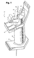
- a nozzle segment generally designated 10, having inner and outer band sections 12 and 14, respectively, adjacent opposite ends of a single nozzle vane 16.
- the illustrated nozzle segment forms one of a plurality of nozzle segments arranged in a circumferential array thereof about a rotor axis to form a nozzle stage of a turbine with the inner and outer band sections 12 and 14, respectively, forming portions of the inner and outer bands of the nozzle stage.
- a single vane 16 is illustrated between the inner and outer band sections 12 and 14, respectively, it will be appreciated that two or more vanes may be disposed between the band sections to form, for example, a vane doublet or triplet.
- the nozzle vane 16 As illustrated, the nozzle vane 16, as well as the inner and outer band sections 12 and 14, have internal cavities which extend the length of the vane. For example, as illustrated in Figure 1, a leading edge cavity 18 is illustrated forward of intermediate cavities 20, 22, 24 and a trailing edge cavity 26. While not forming a part of this invention, it will be appreciated that the cavities provide passages for flowing a thermal medium for cooling the inner and outer bands and vanes which are exposed to the hot gases of combustion flowing along the hot gas path through the turbine. For example, air or steam or both air and steam may be passed through respective cavities to cool the bands and nozzles.
- the nozzle segments 10 are formed of a cast material, preferably a nickel alloy. It will be appreciated that thermal stresses in the nozzles can be minimized by reducing the thickness of the wall exposed to hot gases of combustion and the cooling medium flowing through cavities and this is particularly true with respect to the wall about the leading edge of the vane. It will be appreciated that tolerances and wall thickness controls become increasingly more difficult as the wall thicknesses of the castings are decreased, resulting in reduced casting yields. In accordance with a preferred embodiment of the present invention, improved casting yields, as well as reduced wall thickness, particularly between the outer surface of the leading edge and the interior wall surface of the leading edge cavity, can be accomplished by removing material from the inside surface of the cavity wall by a post-cast electrodischarge machining method.
- an electrode 28 ( Figure 1), e.g., a thin rod, forming part of an electrodischarge machining apparatus is passed into a cavity of the vane 16 between its opposite ends, e.g., through the inner and outer band sections 12 and 14, respectively, and the leading edge cavity 18.
- Electrodischarge machining apparatus is per se conventional.
- the thin electrode 28 is fixtured at opposite ends and is preferably robotically movable to follow a predetermined path along wall 31 of the cast cavity, for example, cavity 18.
- the wall 31 is cast and has a substantial thickness between its cast interior wall surface 30 and exterior wall surface 33 at the leading edge of the vane 16.
- the cast wall thickness is indicated by the distance between the outer wall surface 33 and the dashed line 30 in Figure 2.
- the thin electrode 28 is passed through the cavity 18 and moved to transcribe a surface corresponding to the desired inner wall surface, indicated in Figure 2 by the full line 32, hence forming the desired wall thickness.
- the material of the inner wall of the cavity is cut and may be removed as a single piece, for example, the removed material piece 34 illustrated in Figure 1.
- the thin electrode 28 transcribes a path corresponding to the desired inner wall surface 32 thereby cutting along the wall 31 of the cavity 18, with the result that the desired thin-wall configuration is formed post-cast.
- the path of movement of the electrode 28 along the wall 31 is indicated by the datum points 36 and 38 in Figure 3, at the respective upper and lower ends of the vanes or external to the vanes.
- the desired compound curved surface can be formed along the inside wall of the cavity. It will be appreciated that the electrode 28 extends linearly and maintains its linear extent as it is displaced along the cavity wall.
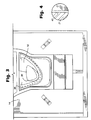
- the thin electrode 28 may have a roughened surface 40, as illustrated in Figure 4. As the thin electrode is displaced along the predetermined path, the interior wall surface is roughened complementary to the roughened surface of the wire electrode for enhanced thermal effectiveness.
- an EDM plunge cut process is used.
- an electrode in the form of a profile is used in lieu of a thin electrode.
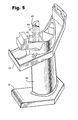
- the profile 42 forms the electrode of the EDM apparatus and extends through the cavity 18 similarly as the thin electrode 28.
- the profile 42 has a forward surface 44 which corresponds to the final desired interior wall surface of the inner cavity after the EDM process is complete.
- the forward surface 44 of the profile 42 is brought to bear against the existing cast interior wall surface 46 of the cavity 18 as illustrated in Figure 6A.
- the final wall surface 48 may be formed.
- the material is cut away until the forward surface 44 of the profile 42 and the interior wall surface 48 are complementary to one another and in the appropriate location within the cavity defining the desired wall thickness.
- the profile 42 may have a roughened surface 50 ( Figure 5) similarly as the thin electrode such that the final interior wall surface 48 of the cavity may have a roughened surface complementary to the roughened surface of the profile for improved heat transfer.
- the wall thickness can be controlled to close tolerances to reduce thermal stresses, as well as improve heat transfer.
Landscapes
- Engineering & Computer Science (AREA)
- Mechanical Engineering (AREA)
- Physics & Mathematics (AREA)
- Thermal Sciences (AREA)
- General Engineering & Computer Science (AREA)
- Electrical Discharge Machining, Electrochemical Machining, And Combined Machining (AREA)
- Turbine Rotor Nozzle Sealing (AREA)
Applications Claiming Priority (2)
| Application Number | Priority Date | Filing Date | Title |
|---|---|---|---|
| US324403 | 1989-03-13 | ||
| US32440399A | 1999-06-02 | 1999-06-02 |
Publications (3)
| Publication Number | Publication Date |
|---|---|
| EP1057565A2 true EP1057565A2 (de) | 2000-12-06 |
| EP1057565A3 EP1057565A3 (de) | 2002-05-15 |
| EP1057565B1 EP1057565B1 (de) | 2006-03-29 |
Family
ID=23263427
Family Applications (1)
| Application Number | Title | Priority Date | Filing Date |
|---|---|---|---|
| EP00304152A Expired - Lifetime EP1057565B1 (de) | 1999-06-02 | 2000-05-17 | Verfahren zur Verminderung der Wandstärke nach dem Giessen einen Turbinenschaufels mittels Funkenerosionsbearbeitung |
Country Status (5)
| Country | Link |
|---|---|
| US (1) | US6388223B2 (de) |
| EP (1) | EP1057565B1 (de) |
| JP (1) | JP4402260B2 (de) |
| KR (1) | KR100489598B1 (de) |
| DE (1) | DE60026934T2 (de) |
Cited By (3)
| Publication number | Priority date | Publication date | Assignee | Title |
|---|---|---|---|---|
| WO2002038330A1 (en) * | 2000-11-09 | 2002-05-16 | Volvo Aero Corporation | A method for manufacturing a vane to a gas turbine component and a method for manufacturing a gas turbine component |
| WO2008049393A1 (de) * | 2006-10-26 | 2008-05-02 | Mtu Aero Engines Gmbh | Verfahren zum herstellen einer leichtbau-turbinenschaufel |
| CN102575581A (zh) * | 2010-01-18 | 2012-07-11 | 三菱重工业株式会社 | 燃气轮机静叶片的插入件去除装置及燃气轮机静叶片的插入件去除方法 |
Families Citing this family (17)
| Publication number | Priority date | Publication date | Assignee | Title |
|---|---|---|---|---|
| US6717095B2 (en) * | 2002-04-18 | 2004-04-06 | General Electric Company | Coolant side surface roughness on airfoil castings by electrical discharge machining (EDM) |
| US6754955B1 (en) * | 2003-01-30 | 2004-06-29 | General Electric Company | Method or repairing trailing edge portions of partitions in turbine diaphragms |
| US7041933B2 (en) * | 2003-04-14 | 2006-05-09 | Meyer Tool, Inc. | Complex hole shaping |
| CA2676135C (en) * | 2003-06-10 | 2011-08-02 | Ihi Corporation | Turbine component, gas turbine engine, production method of turbine component, surface treatment method thereof, blade component, metal component and steam turbine engine |
| US6897400B1 (en) | 2004-03-16 | 2005-05-24 | General Electric Company | Out flushing guide bushing |
| US20050247569A1 (en) * | 2004-05-07 | 2005-11-10 | Lamphere Michael S | Distributed arc electroerosion |
| US7186070B2 (en) * | 2004-10-12 | 2007-03-06 | Honeywell International, Inc. | Method for modifying gas turbine nozzle area |
| US20080142488A1 (en) * | 2006-12-19 | 2008-06-19 | General Electric Company | Compound electrode, methods of manufacture thereof and articles comprising the same |
| US8246306B2 (en) * | 2008-04-03 | 2012-08-21 | General Electric Company | Airfoil for nozzle and a method of forming the machined contoured passage therein |
| US10189100B2 (en) | 2008-07-29 | 2019-01-29 | Pratt & Whitney Canada Corp. | Method for wire electro-discharge machining a part |
| US8925201B2 (en) * | 2009-06-29 | 2015-01-06 | Pratt & Whitney Canada Corp. | Method and apparatus for providing rotor discs |
| US8710392B2 (en) | 2011-06-29 | 2014-04-29 | United Technologies Corporation | Electric discharge machining hole drilling |
| US9121282B2 (en) | 2012-02-02 | 2015-09-01 | Honeywell International Inc. | Methods for the controlled reduction of turbine nozzle flow areas and turbine nozzle components having reduced flow areas |
| ITCO20120054A1 (it) * | 2012-10-31 | 2014-05-01 | Nuovo Pignone Srl | Metodi per produrre pale di turbomacchine mediante wire electric discharge machining, pale e turbomacchine |
| US8720526B1 (en) | 2012-11-13 | 2014-05-13 | Siemens Energy, Inc. | Process for forming a long gas turbine engine blade having a main wall with a thin portion near a tip |
| US10519779B2 (en) * | 2016-03-16 | 2019-12-31 | General Electric Company | Radial CMC wall thickness variation for stress response |
| US11168566B2 (en) | 2016-12-05 | 2021-11-09 | MTU Aero Engines AG | Turbine blade comprising a cavity with wall surface discontinuities and process for the production thereof |
Family Cites Families (10)
| Publication number | Priority date | Publication date | Assignee | Title |
|---|---|---|---|---|
| BE562501A (de) * | 1956-11-20 | |||
| GB846277A (en) | 1956-11-20 | 1960-08-31 | Rolls Royce | Turbine and compressor blades |
| US3920947A (en) | 1972-01-27 | 1975-11-18 | Chromalloy American Corp | Turbine-nozzle manufacturing apparatus and method |
| SU542008A1 (ru) | 1972-11-23 | 1977-01-05 | Предприятие П/Я В-2451 | Способ изготовлени сопловой коробки паровой турбины |
| US5152059A (en) | 1980-09-19 | 1992-10-06 | Rolls-Royce Plc | Manufacture of cooled aerofoil blades |
| US4601638A (en) | 1984-12-21 | 1986-07-22 | United Technologies Corporation | Airfoil trailing edge cooling arrangement |
| GB8725820D0 (en) | 1987-11-04 | 1987-12-09 | Anchem Co Ltd | Machining recess in component |
| JPH0413519A (ja) * | 1990-05-07 | 1992-01-17 | Mitsubishi Heavy Ind Ltd | 電解加工時の短絡防止方法及び工具の制御方法 |
| US5820337A (en) | 1995-01-03 | 1998-10-13 | General Electric Company | Double wall turbine parts |
| US5847350A (en) * | 1997-06-16 | 1998-12-08 | General Electric Company | Adjustable mount |
-
2000
- 2000-05-17 DE DE60026934T patent/DE60026934T2/de not_active Expired - Lifetime
- 2000-05-17 EP EP00304152A patent/EP1057565B1/de not_active Expired - Lifetime
- 2000-05-18 KR KR10-2000-0026634A patent/KR100489598B1/ko not_active Expired - Fee Related
- 2000-06-01 JP JP2000163929A patent/JP4402260B2/ja not_active Expired - Fee Related
- 2000-12-21 US US09/741,767 patent/US6388223B2/en not_active Expired - Lifetime
Non-Patent Citations (1)
| Title |
|---|
| None |
Cited By (5)
| Publication number | Priority date | Publication date | Assignee | Title |
|---|---|---|---|---|
| WO2002038330A1 (en) * | 2000-11-09 | 2002-05-16 | Volvo Aero Corporation | A method for manufacturing a vane to a gas turbine component and a method for manufacturing a gas turbine component |
| WO2008049393A1 (de) * | 2006-10-26 | 2008-05-02 | Mtu Aero Engines Gmbh | Verfahren zum herstellen einer leichtbau-turbinenschaufel |
| CN102575581A (zh) * | 2010-01-18 | 2012-07-11 | 三菱重工业株式会社 | 燃气轮机静叶片的插入件去除装置及燃气轮机静叶片的插入件去除方法 |
| CN102575581B (zh) * | 2010-01-18 | 2014-05-14 | 三菱重工业株式会社 | 燃气轮机静叶片的插入件去除装置及燃气轮机静叶片的插入件去除方法 |
| US8806745B2 (en) | 2010-01-18 | 2014-08-19 | Mitsubishi Heavy Industries, Ltd. | Gas-turbine-stator-vane insert removing device and method of removing gas-turbine-stator-vane insert |
Also Published As
| Publication number | Publication date |
|---|---|
| EP1057565A3 (de) | 2002-05-15 |
| KR20010007082A (ko) | 2001-01-26 |
| EP1057565B1 (de) | 2006-03-29 |
| KR100489598B1 (ko) | 2005-05-16 |
| JP2001132408A (ja) | 2001-05-15 |
| DE60026934D1 (de) | 2006-05-18 |
| US6388223B2 (en) | 2002-05-14 |
| JP4402260B2 (ja) | 2010-01-20 |
| DE60026934T2 (de) | 2006-12-14 |
| US20010002667A1 (en) | 2001-06-07 |
Similar Documents
| Publication | Publication Date | Title |
|---|---|---|
| EP1057565B1 (de) | Verfahren zur Verminderung der Wandstärke nach dem Giessen einen Turbinenschaufels mittels Funkenerosionsbearbeitung | |
| EP1321628B1 (de) | Turbinenleitschaufel einer Gasturbine und deren Herstellungsmethode | |
| EP3157694B1 (de) | Turbinenschaufelfeinguss mit filmlochvorsprüngen zur vollständigen wanddickensteuerung | |
| JP4658584B2 (ja) | 内側寄り冷却式ノズルダブレット | |
| JP3281551B2 (ja) | タービンエンジンの中空羽根の製造方法 | |
| EP2071126B1 (de) | Turbinenschaufeln und Verfahren zur Herstellung von Turbinenschaufeln | |
| EP1279796B1 (de) | Turbinenleitkanal mit einer Stufe und Herstellungsverfahren eines solchen Leitkanals | |
| US6668906B2 (en) | Shaped core for cast cooling passages and enhanced part definition | |
| US4738587A (en) | Cooled highly twisted airfoil for a gas turbine engine | |
| EP3348787B1 (de) | Schaufeldrehkappen in gasturbinenmotoren | |
| JP2007198377A (ja) | 被冷却鋳造部品、被冷却部品製造方法、鋳造部品表面冷却方法、およびガスタービンエンジンエアフォイル構成要素 | |
| JP2006247750A (ja) | 精密インベストメント鋳造用コア | |
| JP2006504023A (ja) | タービンまたはコンプレッサのシートメタル製静止シュラウド | |
| EP1106280B1 (de) | Kern zur Einstellung der Wanddicke einer Turbinenschaufel und Verfahren | |
| US6485262B1 (en) | Methods and apparatus for extending gas turbine engine airfoils useful life | |
| US7578059B2 (en) | Method for manufacturing constituents of a hollow blade by rolling | |
| US20200024965A1 (en) | Component for a turbine engine with a cooling hole | |
| US8277193B1 (en) | Thin walled turbine blade and process for making the blade | |
| EP3065896B1 (de) | Feingussverfahren für ein schaufelsegment eines gasturbinenmotors | |
| JP2017109244A (ja) | ジャケット付きコアを使用して、内部通路を有するコンポーネントを形成するための方法およびアッセンブリ | |
| EP3064290B1 (de) | Kern für ein feingussverfahren | |
| EP3533532A1 (de) | Kern für ein feingussverfahren | |
| US20190270131A1 (en) | Core for an investment casting process |
Legal Events
| Date | Code | Title | Description |
|---|---|---|---|
| PUAI | Public reference made under article 153(3) epc to a published international application that has entered the european phase |
Free format text: ORIGINAL CODE: 0009012 |
|
| AK | Designated contracting states |
Kind code of ref document: A2 Designated state(s): AT BE CH CY DE DK ES FI FR GB GR IE IT LI LU MC NL PT SE |
|
| AX | Request for extension of the european patent |
Free format text: AL;LT;LV;MK;RO;SI |
|
| RIN1 | Information on inventor provided before grant (corrected) |
Inventor name: RAJAN, RAJIV Inventor name: WEI, BIN Inventor name: KIRKPATRICK, FRANCIS LAWRENCE Inventor name: SCHOTSCH, MARGARET JONES Inventor name: BOJAPPA, PARVAGADA GANAPATHY Inventor name: JONES, RAYMOND JOSEPH |
|
| RTI1 | Title (correction) |
Free format text: POST-CAST EDM METHOD FOR REDUCING THE THICKNESS OF A TURBINE NOZZLE WALL |
|
| PUAL | Search report despatched |
Free format text: ORIGINAL CODE: 0009013 |
|
| AK | Designated contracting states |
Kind code of ref document: A3 Designated state(s): AT BE CH CY DE DK ES FI FR GB GR IE IT LI LU MC NL PT SE |
|
| AX | Request for extension of the european patent |
Free format text: AL;LT;LV;MK;RO;SI |
|
| RIC1 | Information provided on ipc code assigned before grant |
Free format text: 7B 23H 9/00 A, 7F 01D 9/00 B, 7B 23H 9/10 B |
|
| 17P | Request for examination filed |
Effective date: 20021115 |
|
| AKX | Designation fees paid |
Designated state(s): CH DE FR GB IT LI |
|
| GRAJ | Information related to disapproval of communication of intention to grant by the applicant or resumption of examination proceedings by the epo deleted |
Free format text: ORIGINAL CODE: EPIDOSDIGR1 |
|
| GRAP | Despatch of communication of intention to grant a patent |
Free format text: ORIGINAL CODE: EPIDOSNIGR1 |
|
| GRAP | Despatch of communication of intention to grant a patent |
Free format text: ORIGINAL CODE: EPIDOSNIGR1 |
|
| GRAS | Grant fee paid |
Free format text: ORIGINAL CODE: EPIDOSNIGR3 |
|
| GRAA | (expected) grant |
Free format text: ORIGINAL CODE: 0009210 |
|
| AK | Designated contracting states |
Kind code of ref document: B1 Designated state(s): CH DE FR GB IT LI |
|
| REG | Reference to a national code |
Ref country code: GB Ref legal event code: FG4D |
|
| RIN1 | Information on inventor provided before grant (corrected) |
Inventor name: KIRKPATRICK, FRANCIS LAWRENCE Inventor name: WEI, BIN Inventor name: BOJAPPA, PARVAGADA GANAPATHY Inventor name: RAJAN, RAJIV Inventor name: JONES, RAYMOND JOSEPH Inventor name: SCHOTSCH, MARGARET JONES |
|
| REG | Reference to a national code |
Ref country code: CH Ref legal event code: EP |
|
| REG | Reference to a national code |
Ref country code: CH Ref legal event code: NV Representative=s name: SERVOPATENT GMBH |
|
| REF | Corresponds to: |
Ref document number: 60026934 Country of ref document: DE Date of ref document: 20060518 Kind code of ref document: P |
|
| ET | Fr: translation filed | ||
| PLBE | No opposition filed within time limit |
Free format text: ORIGINAL CODE: 0009261 |
|
| STAA | Information on the status of an ep patent application or granted ep patent |
Free format text: STATUS: NO OPPOSITION FILED WITHIN TIME LIMIT |
|
| 26N | No opposition filed |
Effective date: 20070102 |
|
| REG | Reference to a national code |
Ref country code: CH Ref legal event code: PFA Owner name: GENERAL ELECTRIC COMPANY Free format text: GENERAL ELECTRIC COMPANY#1 RIVER ROAD#SCHENECTADY, NY 12345 (US) -TRANSFER TO- GENERAL ELECTRIC COMPANY#1 RIVER ROAD#SCHENECTADY, NY 12345 (US) |
|
| REG | Reference to a national code |
Ref country code: FR Ref legal event code: PLFP Year of fee payment: 17 |
|
| PGFP | Annual fee paid to national office [announced via postgrant information from national office to epo] |
Ref country code: GB Payment date: 20160527 Year of fee payment: 17 Ref country code: DE Payment date: 20160527 Year of fee payment: 17 Ref country code: CH Payment date: 20160527 Year of fee payment: 17 |
|
| PGFP | Annual fee paid to national office [announced via postgrant information from national office to epo] |
Ref country code: FR Payment date: 20160530 Year of fee payment: 17 Ref country code: IT Payment date: 20160520 Year of fee payment: 17 |
|
| REG | Reference to a national code |
Ref country code: DE Ref legal event code: R119 Ref document number: 60026934 Country of ref document: DE |
|
| REG | Reference to a national code |
Ref country code: CH Ref legal event code: PL |
|
| GBPC | Gb: european patent ceased through non-payment of renewal fee |
Effective date: 20170517 |
|
| PG25 | Lapsed in a contracting state [announced via postgrant information from national office to epo] |
Ref country code: LI Free format text: LAPSE BECAUSE OF NON-PAYMENT OF DUE FEES Effective date: 20170531 Ref country code: CH Free format text: LAPSE BECAUSE OF NON-PAYMENT OF DUE FEES Effective date: 20170531 |
|
| REG | Reference to a national code |
Ref country code: FR Ref legal event code: ST Effective date: 20180131 |
|
| PG25 | Lapsed in a contracting state [announced via postgrant information from national office to epo] |
Ref country code: GB Free format text: LAPSE BECAUSE OF NON-PAYMENT OF DUE FEES Effective date: 20170517 Ref country code: DE Free format text: LAPSE BECAUSE OF NON-PAYMENT OF DUE FEES Effective date: 20171201 |
|
| PG25 | Lapsed in a contracting state [announced via postgrant information from national office to epo] |
Ref country code: FR Free format text: LAPSE BECAUSE OF NON-PAYMENT OF DUE FEES Effective date: 20170531 Ref country code: IT Free format text: LAPSE BECAUSE OF NON-PAYMENT OF DUE FEES Effective date: 20170517 |