EP1057571A1 - Verfahren und Vorrichtung zum Reibschweissverbinden - Google Patents
Verfahren und Vorrichtung zum Reibschweissverbinden Download PDFInfo
- Publication number
- EP1057571A1 EP1057571A1 EP20000110383 EP00110383A EP1057571A1 EP 1057571 A1 EP1057571 A1 EP 1057571A1 EP 20000110383 EP20000110383 EP 20000110383 EP 00110383 A EP00110383 A EP 00110383A EP 1057571 A1 EP1057571 A1 EP 1057571A1
- Authority
- EP
- European Patent Office
- Prior art keywords
- friction
- activation
- bodies
- friction element
- connecting surfaces
- Prior art date
- Legal status (The legal status is an assumption and is not a legal conclusion. Google has not performed a legal analysis and makes no representation as to the accuracy of the status listed.)
- Withdrawn
Links
Images


Classifications
-
- B—PERFORMING OPERATIONS; TRANSPORTING
- B29—WORKING OF PLASTICS; WORKING OF SUBSTANCES IN A PLASTIC STATE IN GENERAL
- B29C—SHAPING OR JOINING OF PLASTICS; SHAPING OF MATERIAL IN A PLASTIC STATE, NOT OTHERWISE PROVIDED FOR; AFTER-TREATMENT OF THE SHAPED PRODUCTS, e.g. REPAIRING
- B29C65/00—Joining or sealing of preformed parts, e.g. welding of plastics materials; Apparatus therefor
- B29C65/02—Joining or sealing of preformed parts, e.g. welding of plastics materials; Apparatus therefor by heating, with or without pressure
- B29C65/06—Joining or sealing of preformed parts, e.g. welding of plastics materials; Apparatus therefor by heating, with or without pressure using friction, e.g. spin welding
- B29C65/0681—Joining or sealing of preformed parts, e.g. welding of plastics materials; Apparatus therefor by heating, with or without pressure using friction, e.g. spin welding created by a tool
-
- B—PERFORMING OPERATIONS; TRANSPORTING
- B23—MACHINE TOOLS; METAL-WORKING NOT OTHERWISE PROVIDED FOR
- B23K—SOLDERING OR UNSOLDERING; WELDING; CLADDING OR PLATING BY SOLDERING OR WELDING; CUTTING BY APPLYING HEAT LOCALLY, e.g. FLAME CUTTING; WORKING BY LASER BEAM
- B23K20/00—Non-electric welding by applying impact or other pressure, with or without the application of heat, e.g. cladding or plating
- B23K20/12—Non-electric welding by applying impact or other pressure, with or without the application of heat, e.g. cladding or plating the heat being generated by friction; Friction welding
- B23K20/129—Non-electric welding by applying impact or other pressure, with or without the application of heat, e.g. cladding or plating the heat being generated by friction; Friction welding specially adapted for particular articles or work
-
- B—PERFORMING OPERATIONS; TRANSPORTING
- B29—WORKING OF PLASTICS; WORKING OF SUBSTANCES IN A PLASTIC STATE IN GENERAL
- B29C—SHAPING OR JOINING OF PLASTICS; SHAPING OF MATERIAL IN A PLASTIC STATE, NOT OTHERWISE PROVIDED FOR; AFTER-TREATMENT OF THE SHAPED PRODUCTS, e.g. REPAIRING
- B29C66/00—General aspects of processes or apparatus for joining preformed parts
- B29C66/01—General aspects dealing with the joint area or with the area to be joined
- B29C66/05—Particular design of joint configurations
- B29C66/10—Particular design of joint configurations particular design of the joint cross-sections
- B29C66/11—Joint cross-sections comprising a single joint-segment, i.e. one of the parts to be joined comprising a single joint-segment in the joint cross-section
- B29C66/112—Single lapped joints
- B29C66/1122—Single lap to lap joints, i.e. overlap joints
-
- B—PERFORMING OPERATIONS; TRANSPORTING
- B29—WORKING OF PLASTICS; WORKING OF SUBSTANCES IN A PLASTIC STATE IN GENERAL
- B29C—SHAPING OR JOINING OF PLASTICS; SHAPING OF MATERIAL IN A PLASTIC STATE, NOT OTHERWISE PROVIDED FOR; AFTER-TREATMENT OF THE SHAPED PRODUCTS, e.g. REPAIRING
- B29C66/00—General aspects of processes or apparatus for joining preformed parts
- B29C66/40—General aspects of joining substantially flat articles, e.g. plates, sheets or web-like materials; Making flat seams in tubular or hollow articles; Joining single elements to substantially flat surfaces
- B29C66/41—Joining substantially flat articles ; Making flat seams in tubular or hollow articles
-
- B—PERFORMING OPERATIONS; TRANSPORTING
- B29—WORKING OF PLASTICS; WORKING OF SUBSTANCES IN A PLASTIC STATE IN GENERAL
- B29C—SHAPING OR JOINING OF PLASTICS; SHAPING OF MATERIAL IN A PLASTIC STATE, NOT OTHERWISE PROVIDED FOR; AFTER-TREATMENT OF THE SHAPED PRODUCTS, e.g. REPAIRING
- B29C66/00—General aspects of processes or apparatus for joining preformed parts
- B29C66/40—General aspects of joining substantially flat articles, e.g. plates, sheets or web-like materials; Making flat seams in tubular or hollow articles; Joining single elements to substantially flat surfaces
- B29C66/41—Joining substantially flat articles ; Making flat seams in tubular or hollow articles
- B29C66/43—Joining a relatively small portion of the surface of said articles
-
- B—PERFORMING OPERATIONS; TRANSPORTING
- B29—WORKING OF PLASTICS; WORKING OF SUBSTANCES IN A PLASTIC STATE IN GENERAL
- B29C—SHAPING OR JOINING OF PLASTICS; SHAPING OF MATERIAL IN A PLASTIC STATE, NOT OTHERWISE PROVIDED FOR; AFTER-TREATMENT OF THE SHAPED PRODUCTS, e.g. REPAIRING
- B29C66/00—General aspects of processes or apparatus for joining preformed parts
- B29C66/40—General aspects of joining substantially flat articles, e.g. plates, sheets or web-like materials; Making flat seams in tubular or hollow articles; Joining single elements to substantially flat surfaces
- B29C66/47—Joining single elements to sheets, plates or other substantially flat surfaces
- B29C66/472—Joining single elements to sheets, plates or other substantially flat surfaces said single elements being substantially flat
-
- B—PERFORMING OPERATIONS; TRANSPORTING
- B29—WORKING OF PLASTICS; WORKING OF SUBSTANCES IN A PLASTIC STATE IN GENERAL
- B29C—SHAPING OR JOINING OF PLASTICS; SHAPING OF MATERIAL IN A PLASTIC STATE, NOT OTHERWISE PROVIDED FOR; AFTER-TREATMENT OF THE SHAPED PRODUCTS, e.g. REPAIRING
- B29C66/00—General aspects of processes or apparatus for joining preformed parts
- B29C66/70—General aspects of processes or apparatus for joining preformed parts characterised by the composition, physical properties or the structure of the material of the parts to be joined; Joining with non-plastics material
- B29C66/73—General aspects of processes or apparatus for joining preformed parts characterised by the composition, physical properties or the structure of the material of the parts to be joined; Joining with non-plastics material characterised by the intensive physical properties of the material of the parts to be joined, by the optical properties of the material of the parts to be joined, by the extensive physical properties of the parts to be joined, by the state of the material of the parts to be joined or by the material of the parts to be joined being a thermoplastic or a thermoset
- B29C66/737—General aspects of processes or apparatus for joining preformed parts characterised by the composition, physical properties or the structure of the material of the parts to be joined; Joining with non-plastics material characterised by the intensive physical properties of the material of the parts to be joined, by the optical properties of the material of the parts to be joined, by the extensive physical properties of the parts to be joined, by the state of the material of the parts to be joined or by the material of the parts to be joined being a thermoplastic or a thermoset characterised by the state of the material of the parts to be joined
- B29C66/7377—General aspects of processes or apparatus for joining preformed parts characterised by the composition, physical properties or the structure of the material of the parts to be joined; Joining with non-plastics material characterised by the intensive physical properties of the material of the parts to be joined, by the optical properties of the material of the parts to be joined, by the extensive physical properties of the parts to be joined, by the state of the material of the parts to be joined or by the material of the parts to be joined being a thermoplastic or a thermoset characterised by the state of the material of the parts to be joined amorphous, semi-crystalline or crystalline
- B29C66/73771—General aspects of processes or apparatus for joining preformed parts characterised by the composition, physical properties or the structure of the material of the parts to be joined; Joining with non-plastics material characterised by the intensive physical properties of the material of the parts to be joined, by the optical properties of the material of the parts to be joined, by the extensive physical properties of the parts to be joined, by the state of the material of the parts to be joined or by the material of the parts to be joined being a thermoplastic or a thermoset characterised by the state of the material of the parts to be joined amorphous, semi-crystalline or crystalline the to-be-joined area of at least one of the parts to be joined being amorphous
-
- B—PERFORMING OPERATIONS; TRANSPORTING
- B29—WORKING OF PLASTICS; WORKING OF SUBSTANCES IN A PLASTIC STATE IN GENERAL
- B29C—SHAPING OR JOINING OF PLASTICS; SHAPING OF MATERIAL IN A PLASTIC STATE, NOT OTHERWISE PROVIDED FOR; AFTER-TREATMENT OF THE SHAPED PRODUCTS, e.g. REPAIRING
- B29C66/00—General aspects of processes or apparatus for joining preformed parts
- B29C66/70—General aspects of processes or apparatus for joining preformed parts characterised by the composition, physical properties or the structure of the material of the parts to be joined; Joining with non-plastics material
- B29C66/73—General aspects of processes or apparatus for joining preformed parts characterised by the composition, physical properties or the structure of the material of the parts to be joined; Joining with non-plastics material characterised by the intensive physical properties of the material of the parts to be joined, by the optical properties of the material of the parts to be joined, by the extensive physical properties of the parts to be joined, by the state of the material of the parts to be joined or by the material of the parts to be joined being a thermoplastic or a thermoset
- B29C66/739—General aspects of processes or apparatus for joining preformed parts characterised by the composition, physical properties or the structure of the material of the parts to be joined; Joining with non-plastics material characterised by the intensive physical properties of the material of the parts to be joined, by the optical properties of the material of the parts to be joined, by the extensive physical properties of the parts to be joined, by the state of the material of the parts to be joined or by the material of the parts to be joined being a thermoplastic or a thermoset characterised by the material of the parts to be joined being a thermoplastic or a thermoset
- B29C66/7392—General aspects of processes or apparatus for joining preformed parts characterised by the composition, physical properties or the structure of the material of the parts to be joined; Joining with non-plastics material characterised by the intensive physical properties of the material of the parts to be joined, by the optical properties of the material of the parts to be joined, by the extensive physical properties of the parts to be joined, by the state of the material of the parts to be joined or by the material of the parts to be joined being a thermoplastic or a thermoset characterised by the material of the parts to be joined being a thermoplastic or a thermoset characterised by the material of at least one of the parts being a thermoplastic
-
- B—PERFORMING OPERATIONS; TRANSPORTING
- B29—WORKING OF PLASTICS; WORKING OF SUBSTANCES IN A PLASTIC STATE IN GENERAL
- B29C—SHAPING OR JOINING OF PLASTICS; SHAPING OF MATERIAL IN A PLASTIC STATE, NOT OTHERWISE PROVIDED FOR; AFTER-TREATMENT OF THE SHAPED PRODUCTS, e.g. REPAIRING
- B29C66/00—General aspects of processes or apparatus for joining preformed parts
- B29C66/70—General aspects of processes or apparatus for joining preformed parts characterised by the composition, physical properties or the structure of the material of the parts to be joined; Joining with non-plastics material
- B29C66/74—Joining plastics material to non-plastics material
- B29C66/742—Joining plastics material to non-plastics material to metals or their alloys
-
- B—PERFORMING OPERATIONS; TRANSPORTING
- B29—WORKING OF PLASTICS; WORKING OF SUBSTANCES IN A PLASTIC STATE IN GENERAL
- B29C—SHAPING OR JOINING OF PLASTICS; SHAPING OF MATERIAL IN A PLASTIC STATE, NOT OTHERWISE PROVIDED FOR; AFTER-TREATMENT OF THE SHAPED PRODUCTS, e.g. REPAIRING
- B29C66/00—General aspects of processes or apparatus for joining preformed parts
- B29C66/80—General aspects of machine operations or constructions and parts thereof
-
- B—PERFORMING OPERATIONS; TRANSPORTING
- B29—WORKING OF PLASTICS; WORKING OF SUBSTANCES IN A PLASTIC STATE IN GENERAL
- B29C—SHAPING OR JOINING OF PLASTICS; SHAPING OF MATERIAL IN A PLASTIC STATE, NOT OTHERWISE PROVIDED FOR; AFTER-TREATMENT OF THE SHAPED PRODUCTS, e.g. REPAIRING
- B29C66/00—General aspects of processes or apparatus for joining preformed parts
- B29C66/80—General aspects of machine operations or constructions and parts thereof
- B29C66/82—Pressure application arrangements, e.g. transmission or actuating mechanisms for joining tools or clamps
- B29C66/824—Actuating mechanisms
- B29C66/8242—Pneumatic or hydraulic drives
-
- B—PERFORMING OPERATIONS; TRANSPORTING
- B29—WORKING OF PLASTICS; WORKING OF SUBSTANCES IN A PLASTIC STATE IN GENERAL
- B29C—SHAPING OR JOINING OF PLASTICS; SHAPING OF MATERIAL IN A PLASTIC STATE, NOT OTHERWISE PROVIDED FOR; AFTER-TREATMENT OF THE SHAPED PRODUCTS, e.g. REPAIRING
- B29C66/00—General aspects of processes or apparatus for joining preformed parts
- B29C66/80—General aspects of machine operations or constructions and parts thereof
- B29C66/83—General aspects of machine operations or constructions and parts thereof characterised by the movement of the joining or pressing tools
- B29C66/836—Moving relative to and tangentially to the parts to be joined, e.g. transversely to the displacement of the parts to be joined, e.g. using a X-Y table
-
- B—PERFORMING OPERATIONS; TRANSPORTING
- B29—WORKING OF PLASTICS; WORKING OF SUBSTANCES IN A PLASTIC STATE IN GENERAL
- B29C—SHAPING OR JOINING OF PLASTICS; SHAPING OF MATERIAL IN A PLASTIC STATE, NOT OTHERWISE PROVIDED FOR; AFTER-TREATMENT OF THE SHAPED PRODUCTS, e.g. REPAIRING
- B29C66/00—General aspects of processes or apparatus for joining preformed parts
- B29C66/90—Measuring or controlling the joining process
- B29C66/91—Measuring or controlling the joining process by measuring or controlling the temperature, the heat or the thermal flux
- B29C66/912—Measuring or controlling the joining process by measuring or controlling the temperature, the heat or the thermal flux by measuring the temperature, the heat or the thermal flux
- B29C66/9121—Measuring or controlling the joining process by measuring or controlling the temperature, the heat or the thermal flux by measuring the temperature, the heat or the thermal flux by measuring the temperature
-
- B—PERFORMING OPERATIONS; TRANSPORTING
- B29—WORKING OF PLASTICS; WORKING OF SUBSTANCES IN A PLASTIC STATE IN GENERAL
- B29C—SHAPING OR JOINING OF PLASTICS; SHAPING OF MATERIAL IN A PLASTIC STATE, NOT OTHERWISE PROVIDED FOR; AFTER-TREATMENT OF THE SHAPED PRODUCTS, e.g. REPAIRING
- B29C66/00—General aspects of processes or apparatus for joining preformed parts
- B29C66/90—Measuring or controlling the joining process
- B29C66/91—Measuring or controlling the joining process by measuring or controlling the temperature, the heat or the thermal flux
- B29C66/912—Measuring or controlling the joining process by measuring or controlling the temperature, the heat or the thermal flux by measuring the temperature, the heat or the thermal flux
- B29C66/9121—Measuring or controlling the joining process by measuring or controlling the temperature, the heat or the thermal flux by measuring the temperature, the heat or the thermal flux by measuring the temperature
- B29C66/91211—Measuring or controlling the joining process by measuring or controlling the temperature, the heat or the thermal flux by measuring the temperature, the heat or the thermal flux by measuring the temperature with special temperature measurement means or methods
- B29C66/91212—Measuring or controlling the joining process by measuring or controlling the temperature, the heat or the thermal flux by measuring the temperature, the heat or the thermal flux by measuring the temperature with special temperature measurement means or methods involving measurement means being part of the welding jaws, e.g. integrated in the welding jaws
-
- B—PERFORMING OPERATIONS; TRANSPORTING
- B29—WORKING OF PLASTICS; WORKING OF SUBSTANCES IN A PLASTIC STATE IN GENERAL
- B29C—SHAPING OR JOINING OF PLASTICS; SHAPING OF MATERIAL IN A PLASTIC STATE, NOT OTHERWISE PROVIDED FOR; AFTER-TREATMENT OF THE SHAPED PRODUCTS, e.g. REPAIRING
- B29C66/00—General aspects of processes or apparatus for joining preformed parts
- B29C66/90—Measuring or controlling the joining process
- B29C66/91—Measuring or controlling the joining process by measuring or controlling the temperature, the heat or the thermal flux
- B29C66/912—Measuring or controlling the joining process by measuring or controlling the temperature, the heat or the thermal flux by measuring the temperature, the heat or the thermal flux
- B29C66/9121—Measuring or controlling the joining process by measuring or controlling the temperature, the heat or the thermal flux by measuring the temperature, the heat or the thermal flux by measuring the temperature
- B29C66/91221—Measuring or controlling the joining process by measuring or controlling the temperature, the heat or the thermal flux by measuring the temperature, the heat or the thermal flux by measuring the temperature of the parts to be joined
-
- B—PERFORMING OPERATIONS; TRANSPORTING
- B23—MACHINE TOOLS; METAL-WORKING NOT OTHERWISE PROVIDED FOR
- B23K—SOLDERING OR UNSOLDERING; WELDING; CLADDING OR PLATING BY SOLDERING OR WELDING; CUTTING BY APPLYING HEAT LOCALLY, e.g. FLAME CUTTING; WORKING BY LASER BEAM
- B23K2101/00—Articles made by soldering, welding or cutting
- B23K2101/16—Bands or sheets of indefinite length
-
- B—PERFORMING OPERATIONS; TRANSPORTING
- B29—WORKING OF PLASTICS; WORKING OF SUBSTANCES IN A PLASTIC STATE IN GENERAL
- B29C—SHAPING OR JOINING OF PLASTICS; SHAPING OF MATERIAL IN A PLASTIC STATE, NOT OTHERWISE PROVIDED FOR; AFTER-TREATMENT OF THE SHAPED PRODUCTS, e.g. REPAIRING
- B29C66/00—General aspects of processes or apparatus for joining preformed parts
- B29C66/70—General aspects of processes or apparatus for joining preformed parts characterised by the composition, physical properties or the structure of the material of the parts to be joined; Joining with non-plastics material
- B29C66/73—General aspects of processes or apparatus for joining preformed parts characterised by the composition, physical properties or the structure of the material of the parts to be joined; Joining with non-plastics material characterised by the intensive physical properties of the material of the parts to be joined, by the optical properties of the material of the parts to be joined, by the extensive physical properties of the parts to be joined, by the state of the material of the parts to be joined or by the material of the parts to be joined being a thermoplastic or a thermoset
- B29C66/731—General aspects of processes or apparatus for joining preformed parts characterised by the composition, physical properties or the structure of the material of the parts to be joined; Joining with non-plastics material characterised by the intensive physical properties of the material of the parts to be joined, by the optical properties of the material of the parts to be joined, by the extensive physical properties of the parts to be joined, by the state of the material of the parts to be joined or by the material of the parts to be joined being a thermoplastic or a thermoset characterised by the intensive physical properties of the material of the parts to be joined
- B29C66/7315—Mechanical properties
- B29C66/73151—Hardness
- B29C66/73152—Hardness of different hardness, i.e. the hardness of one of the parts to be joined being different from the hardness of the other part
-
- B—PERFORMING OPERATIONS; TRANSPORTING
- B29—WORKING OF PLASTICS; WORKING OF SUBSTANCES IN A PLASTIC STATE IN GENERAL
- B29C—SHAPING OR JOINING OF PLASTICS; SHAPING OF MATERIAL IN A PLASTIC STATE, NOT OTHERWISE PROVIDED FOR; AFTER-TREATMENT OF THE SHAPED PRODUCTS, e.g. REPAIRING
- B29C66/00—General aspects of processes or apparatus for joining preformed parts
- B29C66/70—General aspects of processes or apparatus for joining preformed parts characterised by the composition, physical properties or the structure of the material of the parts to be joined; Joining with non-plastics material
- B29C66/73—General aspects of processes or apparatus for joining preformed parts characterised by the composition, physical properties or the structure of the material of the parts to be joined; Joining with non-plastics material characterised by the intensive physical properties of the material of the parts to be joined, by the optical properties of the material of the parts to be joined, by the extensive physical properties of the parts to be joined, by the state of the material of the parts to be joined or by the material of the parts to be joined being a thermoplastic or a thermoset
- B29C66/731—General aspects of processes or apparatus for joining preformed parts characterised by the composition, physical properties or the structure of the material of the parts to be joined; Joining with non-plastics material characterised by the intensive physical properties of the material of the parts to be joined, by the optical properties of the material of the parts to be joined, by the extensive physical properties of the parts to be joined, by the state of the material of the parts to be joined or by the material of the parts to be joined being a thermoplastic or a thermoset characterised by the intensive physical properties of the material of the parts to be joined
- B29C66/7316—Surface properties
- B29C66/73161—Roughness or rugosity
-
- B—PERFORMING OPERATIONS; TRANSPORTING
- B29—WORKING OF PLASTICS; WORKING OF SUBSTANCES IN A PLASTIC STATE IN GENERAL
- B29C—SHAPING OR JOINING OF PLASTICS; SHAPING OF MATERIAL IN A PLASTIC STATE, NOT OTHERWISE PROVIDED FOR; AFTER-TREATMENT OF THE SHAPED PRODUCTS, e.g. REPAIRING
- B29C66/00—General aspects of processes or apparatus for joining preformed parts
- B29C66/70—General aspects of processes or apparatus for joining preformed parts characterised by the composition, physical properties or the structure of the material of the parts to be joined; Joining with non-plastics material
- B29C66/73—General aspects of processes or apparatus for joining preformed parts characterised by the composition, physical properties or the structure of the material of the parts to be joined; Joining with non-plastics material characterised by the intensive physical properties of the material of the parts to be joined, by the optical properties of the material of the parts to be joined, by the extensive physical properties of the parts to be joined, by the state of the material of the parts to be joined or by the material of the parts to be joined being a thermoplastic or a thermoset
- B29C66/731—General aspects of processes or apparatus for joining preformed parts characterised by the composition, physical properties or the structure of the material of the parts to be joined; Joining with non-plastics material characterised by the intensive physical properties of the material of the parts to be joined, by the optical properties of the material of the parts to be joined, by the extensive physical properties of the parts to be joined, by the state of the material of the parts to be joined or by the material of the parts to be joined being a thermoplastic or a thermoset characterised by the intensive physical properties of the material of the parts to be joined
- B29C66/7316—Surface properties
- B29C66/73161—Roughness or rugosity
- B29C66/73162—Roughness or rugosity of different roughness or rugosity, i.e. the roughness or rugosity of the surface of one of the parts to be joined being different from the roughness or rugosity of the surface of the other part
-
- B—PERFORMING OPERATIONS; TRANSPORTING
- B29—WORKING OF PLASTICS; WORKING OF SUBSTANCES IN A PLASTIC STATE IN GENERAL
- B29C—SHAPING OR JOINING OF PLASTICS; SHAPING OF MATERIAL IN A PLASTIC STATE, NOT OTHERWISE PROVIDED FOR; AFTER-TREATMENT OF THE SHAPED PRODUCTS, e.g. REPAIRING
- B29C66/00—General aspects of processes or apparatus for joining preformed parts
- B29C66/70—General aspects of processes or apparatus for joining preformed parts characterised by the composition, physical properties or the structure of the material of the parts to be joined; Joining with non-plastics material
- B29C66/73—General aspects of processes or apparatus for joining preformed parts characterised by the composition, physical properties or the structure of the material of the parts to be joined; Joining with non-plastics material characterised by the intensive physical properties of the material of the parts to be joined, by the optical properties of the material of the parts to be joined, by the extensive physical properties of the parts to be joined, by the state of the material of the parts to be joined or by the material of the parts to be joined being a thermoplastic or a thermoset
- B29C66/737—General aspects of processes or apparatus for joining preformed parts characterised by the composition, physical properties or the structure of the material of the parts to be joined; Joining with non-plastics material characterised by the intensive physical properties of the material of the parts to be joined, by the optical properties of the material of the parts to be joined, by the extensive physical properties of the parts to be joined, by the state of the material of the parts to be joined or by the material of the parts to be joined being a thermoplastic or a thermoset characterised by the state of the material of the parts to be joined
- B29C66/7377—General aspects of processes or apparatus for joining preformed parts characterised by the composition, physical properties or the structure of the material of the parts to be joined; Joining with non-plastics material characterised by the intensive physical properties of the material of the parts to be joined, by the optical properties of the material of the parts to be joined, by the extensive physical properties of the parts to be joined, by the state of the material of the parts to be joined or by the material of the parts to be joined being a thermoplastic or a thermoset characterised by the state of the material of the parts to be joined amorphous, semi-crystalline or crystalline
- B29C66/73771—General aspects of processes or apparatus for joining preformed parts characterised by the composition, physical properties or the structure of the material of the parts to be joined; Joining with non-plastics material characterised by the intensive physical properties of the material of the parts to be joined, by the optical properties of the material of the parts to be joined, by the extensive physical properties of the parts to be joined, by the state of the material of the parts to be joined or by the material of the parts to be joined being a thermoplastic or a thermoset characterised by the state of the material of the parts to be joined amorphous, semi-crystalline or crystalline the to-be-joined area of at least one of the parts to be joined being amorphous
- B29C66/73772—General aspects of processes or apparatus for joining preformed parts characterised by the composition, physical properties or the structure of the material of the parts to be joined; Joining with non-plastics material characterised by the intensive physical properties of the material of the parts to be joined, by the optical properties of the material of the parts to be joined, by the extensive physical properties of the parts to be joined, by the state of the material of the parts to be joined or by the material of the parts to be joined being a thermoplastic or a thermoset characterised by the state of the material of the parts to be joined amorphous, semi-crystalline or crystalline the to-be-joined area of at least one of the parts to be joined being amorphous the to-be-joined areas of both parts to be joined being amorphous
-
- B—PERFORMING OPERATIONS; TRANSPORTING
- B29—WORKING OF PLASTICS; WORKING OF SUBSTANCES IN A PLASTIC STATE IN GENERAL
- B29C—SHAPING OR JOINING OF PLASTICS; SHAPING OF MATERIAL IN A PLASTIC STATE, NOT OTHERWISE PROVIDED FOR; AFTER-TREATMENT OF THE SHAPED PRODUCTS, e.g. REPAIRING
- B29C66/00—General aspects of processes or apparatus for joining preformed parts
- B29C66/70—General aspects of processes or apparatus for joining preformed parts characterised by the composition, physical properties or the structure of the material of the parts to be joined; Joining with non-plastics material
- B29C66/73—General aspects of processes or apparatus for joining preformed parts characterised by the composition, physical properties or the structure of the material of the parts to be joined; Joining with non-plastics material characterised by the intensive physical properties of the material of the parts to be joined, by the optical properties of the material of the parts to be joined, by the extensive physical properties of the parts to be joined, by the state of the material of the parts to be joined or by the material of the parts to be joined being a thermoplastic or a thermoset
- B29C66/739—General aspects of processes or apparatus for joining preformed parts characterised by the composition, physical properties or the structure of the material of the parts to be joined; Joining with non-plastics material characterised by the intensive physical properties of the material of the parts to be joined, by the optical properties of the material of the parts to be joined, by the extensive physical properties of the parts to be joined, by the state of the material of the parts to be joined or by the material of the parts to be joined being a thermoplastic or a thermoset characterised by the material of the parts to be joined being a thermoplastic or a thermoset
- B29C66/7392—General aspects of processes or apparatus for joining preformed parts characterised by the composition, physical properties or the structure of the material of the parts to be joined; Joining with non-plastics material characterised by the intensive physical properties of the material of the parts to be joined, by the optical properties of the material of the parts to be joined, by the extensive physical properties of the parts to be joined, by the state of the material of the parts to be joined or by the material of the parts to be joined being a thermoplastic or a thermoset characterised by the material of the parts to be joined being a thermoplastic or a thermoset characterised by the material of at least one of the parts being a thermoplastic
- B29C66/73921—General aspects of processes or apparatus for joining preformed parts characterised by the composition, physical properties or the structure of the material of the parts to be joined; Joining with non-plastics material characterised by the intensive physical properties of the material of the parts to be joined, by the optical properties of the material of the parts to be joined, by the extensive physical properties of the parts to be joined, by the state of the material of the parts to be joined or by the material of the parts to be joined being a thermoplastic or a thermoset characterised by the material of the parts to be joined being a thermoplastic or a thermoset characterised by the material of at least one of the parts being a thermoplastic characterised by the materials of both parts being thermoplastics
-
- B—PERFORMING OPERATIONS; TRANSPORTING
- B29—WORKING OF PLASTICS; WORKING OF SUBSTANCES IN A PLASTIC STATE IN GENERAL
- B29C—SHAPING OR JOINING OF PLASTICS; SHAPING OF MATERIAL IN A PLASTIC STATE, NOT OTHERWISE PROVIDED FOR; AFTER-TREATMENT OF THE SHAPED PRODUCTS, e.g. REPAIRING
- B29C66/00—General aspects of processes or apparatus for joining preformed parts
- B29C66/80—General aspects of machine operations or constructions and parts thereof
- B29C66/81—General aspects of the pressing elements, i.e. the elements applying pressure on the parts to be joined in the area to be joined, e.g. the welding jaws or clamps
- B29C66/812—General aspects of the pressing elements, i.e. the elements applying pressure on the parts to be joined in the area to be joined, e.g. the welding jaws or clamps characterised by the composition, by the structure, by the intensive physical properties or by the optical properties of the material constituting the pressing elements, e.g. constituting the welding jaws or clamps
- B29C66/8126—General aspects of the pressing elements, i.e. the elements applying pressure on the parts to be joined in the area to be joined, e.g. the welding jaws or clamps characterised by the composition, by the structure, by the intensive physical properties or by the optical properties of the material constituting the pressing elements, e.g. constituting the welding jaws or clamps characterised by the intensive physical properties or by the optical properties of the material constituting the pressing elements, e.g. constituting the welding jaws or clamps
- B29C66/81264—Mechanical properties, e.g. hardness
-
- B—PERFORMING OPERATIONS; TRANSPORTING
- B29—WORKING OF PLASTICS; WORKING OF SUBSTANCES IN A PLASTIC STATE IN GENERAL
- B29C—SHAPING OR JOINING OF PLASTICS; SHAPING OF MATERIAL IN A PLASTIC STATE, NOT OTHERWISE PROVIDED FOR; AFTER-TREATMENT OF THE SHAPED PRODUCTS, e.g. REPAIRING
- B29C66/00—General aspects of processes or apparatus for joining preformed parts
- B29C66/80—General aspects of machine operations or constructions and parts thereof
- B29C66/81—General aspects of the pressing elements, i.e. the elements applying pressure on the parts to be joined in the area to be joined, e.g. the welding jaws or clamps
- B29C66/812—General aspects of the pressing elements, i.e. the elements applying pressure on the parts to be joined in the area to be joined, e.g. the welding jaws or clamps characterised by the composition, by the structure, by the intensive physical properties or by the optical properties of the material constituting the pressing elements, e.g. constituting the welding jaws or clamps
- B29C66/8126—General aspects of the pressing elements, i.e. the elements applying pressure on the parts to be joined in the area to be joined, e.g. the welding jaws or clamps characterised by the composition, by the structure, by the intensive physical properties or by the optical properties of the material constituting the pressing elements, e.g. constituting the welding jaws or clamps characterised by the intensive physical properties or by the optical properties of the material constituting the pressing elements, e.g. constituting the welding jaws or clamps
- B29C66/81265—Surface properties, e.g. surface roughness or rugosity
-
- B—PERFORMING OPERATIONS; TRANSPORTING
- B29—WORKING OF PLASTICS; WORKING OF SUBSTANCES IN A PLASTIC STATE IN GENERAL
- B29C—SHAPING OR JOINING OF PLASTICS; SHAPING OF MATERIAL IN A PLASTIC STATE, NOT OTHERWISE PROVIDED FOR; AFTER-TREATMENT OF THE SHAPED PRODUCTS, e.g. REPAIRING
- B29C66/00—General aspects of processes or apparatus for joining preformed parts
- B29C66/90—Measuring or controlling the joining process
- B29C66/92—Measuring or controlling the joining process by measuring or controlling the pressure, the force, the mechanical power or the displacement of the joining tools
- B29C66/922—Measuring or controlling the joining process by measuring or controlling the pressure, the force, the mechanical power or the displacement of the joining tools by measuring the pressure, the force, the mechanical power or the displacement of the joining tools
- B29C66/9221—Measuring or controlling the joining process by measuring or controlling the pressure, the force, the mechanical power or the displacement of the joining tools by measuring the pressure, the force, the mechanical power or the displacement of the joining tools by measuring the pressure, the force or the mechanical power
-
- B—PERFORMING OPERATIONS; TRANSPORTING
- B29—WORKING OF PLASTICS; WORKING OF SUBSTANCES IN A PLASTIC STATE IN GENERAL
- B29C—SHAPING OR JOINING OF PLASTICS; SHAPING OF MATERIAL IN A PLASTIC STATE, NOT OTHERWISE PROVIDED FOR; AFTER-TREATMENT OF THE SHAPED PRODUCTS, e.g. REPAIRING
- B29C66/00—General aspects of processes or apparatus for joining preformed parts
- B29C66/90—Measuring or controlling the joining process
- B29C66/92—Measuring or controlling the joining process by measuring or controlling the pressure, the force, the mechanical power or the displacement of the joining tools
- B29C66/924—Measuring or controlling the joining process by measuring or controlling the pressure, the force, the mechanical power or the displacement of the joining tools by controlling or regulating the pressure, the force, the mechanical power or the displacement of the joining tools
- B29C66/9241—Measuring or controlling the joining process by measuring or controlling the pressure, the force, the mechanical power or the displacement of the joining tools by controlling or regulating the pressure, the force, the mechanical power or the displacement of the joining tools by controlling or regulating the pressure, the force or the mechanical power
-
- B—PERFORMING OPERATIONS; TRANSPORTING
- B29—WORKING OF PLASTICS; WORKING OF SUBSTANCES IN A PLASTIC STATE IN GENERAL
- B29C—SHAPING OR JOINING OF PLASTICS; SHAPING OF MATERIAL IN A PLASTIC STATE, NOT OTHERWISE PROVIDED FOR; AFTER-TREATMENT OF THE SHAPED PRODUCTS, e.g. REPAIRING
- B29C66/00—General aspects of processes or apparatus for joining preformed parts
- B29C66/90—Measuring or controlling the joining process
- B29C66/96—Measuring or controlling the joining process characterised by the method for implementing the controlling of the joining process
- B29C66/961—Measuring or controlling the joining process characterised by the method for implementing the controlling of the joining process involving a feedback loop mechanism, e.g. comparison with a desired value
Definitions
- the invention relates to a method according to the preamble of claim 1 and a device according to the preamble of claim 7.
- plastics and metal production technology including bodies to be able to connect to one another by friction welding, which are not rotationally symmetrical Have connecting surfaces or are not themselves rotationally symmetrical.
- plastic and / or metal materials i.e. Materials, that differ in their weldability, through each other
- plastic bodies with metal bodies connect, regardless of whether they have rotationally symmetrical connection surfaces or not.
- the invention has for its object a method of the type mentioned and to provide a device for performing the method with which Plastic and / or metal body without rotationally symmetrical connecting surfaces or rotationally symmetrical shape are easily weldable, namely largely independent of the geometry of the connecting surfaces or the shape the grains, and to achieve a high quality and resilient connection.
- each connecting surface is made without direct Contact with the other activated for itself before the welding takes place. Before welding, the friction element is removed so that it is on the weld does not participate. This makes the process independent of the geometric one Shape of the connecting surfaces or the shape of the grains.
- Sandra can Activate the connection surface exactly to the point, so that a high quality of the Friction weld connection can be achieved regardless of the geometry and true to the angle is.
- the connecting surfaces can be almost linear or point-shaped, partial or be full-surface. Due to the relative movement between the connecting surface and the friction element activates every point of the connecting surface equally, which leads to a homogeneous friction weld connection.
- Frictional heat is caused by the frictional relationships between each connecting surface and the friction element, the relative speed, the contact pressure and the Exposure time can be precisely controlled, and these parameters can be selected over a wide range are. If necessary, the friction element can be additionally heated in order to save time shorten for activation.
- the friction element becomes continuous or oscillating, i.e. driven back and forth. Also egg movements of the friction element similar to the movement in an orbital orbital sander useful for an effective and uniform activation of the connecting surfaces his.
- a continuous movement is a movement of the friction element understood in one direction, either at constant speed or with a certain speed profile with acceleration and deceleration phases he follows.
- the bodies to be connected are positioned exactly relative to one another and pressed to the tape.
- This is a hard elastic Material existing tape that is pulled between the connecting surfaces becomes.
- the belt is moved relative to the connection surfaces until everyone Point of the connecting surfaces is sufficiently activated.
- At least one Band facing the connection surface is expediently frictionally active structured activation surface.
- the tape is removed and the Connection surfaces pressed against each other. This way it becomes a very homogeneous one and angled friction weld connection possible.
- the expenditure on equipment is low.
- the device is universal for different materials and / or different Geometric shapes of the bodies can be used.
- connection surface By amorphous plastic bodies to be joined together, or a body made from amorphous plastic with another plastic or metal body, it can be appropriate, the activation of the respective connection surface by from the outside to support supplied thermal energy at least temporarily. With bodies from different soft materials can activate the connection surface harder material can be supported by external heat energy.
- the activation surfaces of the friction element can be substantially the same.
- different materials or bodies are made with regard to the welding properties to connect different materials, then you can the activation surfaces of the friction element have different friction properties own, e.g. such that with the same relative movement of the friction element on both Connection surfaces in the connection surface from the less sweat-friendly Higher frictional power is provided.
- the activation surfaces can differ not only in their friction properties, but also through their structuring, which also determines the friction properties, accordingly the respective material characteristics.
- connection surfaces can be made for the two mutual connection surfaces
- Use friction elements each on the material or welding behavior the connecting surface acted upon by him can be coordinated.
- the two Friction elements can have the same or different friction properties on their activation surfaces own or with the same or different relative speeds or driven with the same or different contact pressures become. In this way, they can ultimately be used for the respective activation effect coordinate key parameters in a wide range so that Both connection surfaces are then activated exactly to the point when the friction elements removed and the bodies pressed against each other.
- sandwich-like friction welded products can be made from more than form two bodies in a process cycle. This multi-part sandwich connection can be performed on several such groups at the same time in order to to achieve higher output.
- connection surface It is either a separate band for each connection surface or for the two mutual ones Connection areas provided a common band. This makes possible the targeted activation of each connection surface while adapting to the welding behavior of the respective material. This allows bodies to be different Add sizes or friction properties or from different materials.
- the band is either endless or finite. It is preferably a Sheet steel strip with at least one structured or coated activation surface or around a sanding belt.
- the two activation surfaces of the tape or the two tapes can be used be structurally active in the same or different ways, so that in an activation cycle the mutual connection surfaces at exactly the same time are activated when they are pressed against each other.
- the two belts can be driven so that they are the same or different Have relative speeds relative to their connecting surfaces.
- the respective contact pressure can also be set the same or different, for example by means of the pressing device of the friction welding device. To this way, the parameters that are jointly decisive for the activation can be predetermine or set precisely.
- Heat source are used with the additional thermal energy in at least one Connection surface can be introduced.
- the oscillating movement of the band can be measured in frequency and amplitude Adjust for optimal activation of each connection surface.
- the finite tape with the tape reel drive is structurally simple over a certain one Distance and with a certain speed profile between the connecting surfaces pulled through. Only when the end of the tape has emerged are the Connection surfaces pressed against each other.
- Each band is expedient in terms of its material and / or its activation surface on the material that comes into contact with it Connection area coordinated such that both connection surfaces to the activated at the same time as weldable and pressed against each other can.
- the two tapes lying on top of each other can be separated Drive and drive individually if necessary. Since they are against each other by the contact pressure pressed, it should slide smoothly in the mutual contact area coated and / or lubricated.
- a body K1 with another body K2 in mutual, essentially flat connecting surfaces V1, V2 are connected by friction welding. At least the mutual connection surfaces V1, V2 are not rotationally symmetrical.
- the bodies K1, K2 also have different shapes and dimensions.
- Both Bodies K1, K2 can consist of plastic or metal or of different, however, weldable materials such as plastic or metal.
- the welding properties in the connecting surfaces V1, V2 can be approximately the same, but also be clearly different from each other.
- the two bodies K1, K2 are positioned relative to one another without their connecting surfaces Touch V1, V2. Rather, between the connecting surfaces V1, V2 a friction element R against which the connecting surfaces V1, V2 with a certain Contact pressure F1 are pressed.
- the friction element R is positioned relative to the Bodies K1, K2 in the direction of an arrow T, for example, essentially continuous speed and linearly driven, with an upper activation surface A1 of the friction element R the connecting surface V1 and a lower one Activation surface A2 of the friction element R applies friction to the other connecting surface V2.
- Special surface structuring can be carried out on the activation surfaces A1, A2 be provided, e.g. a certain, essentially uniform Roughness, a covering similar to an emery, or a serrated, corrugated or treated by plasma spraying or sandblasting and the like. Surface structure.
- the friction element R can be oscillated back and forth in accordance with the double arrow T1, either with constant amplitude and frequency or with variable frequency and / or amplitude of movement. With the relative movement the contact pressure F1 can be kept constant or reduced or increased or dying to be changed.
- the connecting surfaces V1, V2 up to Weldability activated, i.e. plasticized or melted in the contact area. If the two connecting surfaces V1, V2 are activated until they are weldable, what, for example, by controlling the exposure time of the friction and the other aforementioned parameter is caused, then the friction element R removed and the two grains, K1, K2 with their connecting surfaces V1, V2 pressed against each other, with a contact pressure F2. After that is one full-area, a punctiform or a linear form within the connecting areas V1, V2 Friction welded connection made.
- Dashed lines in Fig. 1 indicate that instead of a single friction element R two superimposed friction elements R1, R2 can be provided, either with the same movements T, T1 or with different movements T, T1 are driven and similar or different activation surfaces A1, Own A2.
- the connecting surfaces V1, V2 are approximately frame-like in FIG. 1. she could, however, be full-area or approximately linear or even approximate punctiform.
- FIG. 2 illustrates the method for connecting two grains K1, K2 by means of one single common friction elements R that either continuously in one direction or is driven oscillating back and forth. It is possible to use the friction element eager to drive. The two grains are pressed against each other as soon as the friction element is removed after activation of the connecting surfaces, or after which the two bodies have been moved away from the friction element R after activation are.
- FIG. 3 two pairs P1, P2 of bodies K1 to K4 are common and simultaneously processed, namely by means of a common friction element R.
- Fig. 2 or Fig. 3 could also dashed the two in Fig. 1 instead of a single friction element indicated friction elements R1, R2 are used.
- At least one group G1 is made up of more than two bodies K at the same time friction welded, in this case by means of two friction elements R, which between the respective opposite connecting surfaces are moved. It leaves to produce a sandwich-like end product from several bodies. Each friction element could be driven continuously or oscillating. It would be conceivable to use only a single friction element R, which between the is diverted on both working levels. Furthermore, it is indicated in FIG. 4 that at the same time also a second group G2 made of more than two bodies friction welded becomes.
- a heating device H is additionally provided with the external heat W can be brought into effect in at least one connecting surface is.
- This can be useful for a body K1 made of amorphous plastic, and another body made of a different plastic or metal. Further this process variant can be useful to differently soft materials the body K1, K2 to be able to connect, and the harder material through the additional heat W towards the same softness in the same treatment time activate like the other material.
- each friction element R1, R2 can be driven either continuously or in an oscillating manner.
- Friction element R1, R2 is provided only one activation surface A1, A2, wherein these can be the same or different.
- the mutual contact area B of the two friction elements R1, R2 should expediently slide surfaces or even lubrication may be provided.
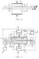
- FIG. 7 illustrates a specific embodiment of a device D for friction welding, for example two plate-shaped or foil-shaped bodies K1, K2.
- the device D has a machine frame, not shown, in which plate-shaped Positioning parts E1 and E2 are arranged so as to be adjustable relative to one another.
- the Positioning part E1 is acted upon by a pressing device G1, for example one Hydraulic cylinder 2, which has a valve device 3 in terms of pressure and Hubs is controllable.
- the positioning part E2 is similarly by a pressing device G2 acted upon, namely a hydraulic cylinder 2 and a control device 3.
- One of the two positioning parts E1, E2 could be stationary in the device D be stored.
- the positioning part E1, E2 positions a grain K1 or K2 such that the two connecting surfaces V1, V2 face each other, but face each other do not touch.
- the connecting surfaces V1, V2 provided as a hard, elastic or flexible band 4 friction element R.
- a drive M is used to move the friction element R in the direction of the arrow T. provided that e.g. interacts with a winding drive 5, 6 of the belt 4.
- the Volume 4 is finite and wound onto the two winding cores of the winding drive 5, 6.
- the friction element R has the activation surfaces A1, A1, which under the contact pressure generated by the cylinders 2 bear on the connecting surfaces V1, V2.
- the connecting surfaces V1, V2 can run flat or curved because the band 4 is also able to adapt to curvatures.
- sensors S can be provided which measure temperatures, pressures, strokes or the like and transmit to a control device C.
- To the control device C are also the control valves 3 and the drive M connected.
- the connecting surfaces V1, V2 are counteracted with the contact pressure F1 the activation surfaces A1, A2 pressed.
- the width of the band 4 can be considerable be larger than the width dimension of the connecting surfaces V1, V2. It can also Band 4 may be longer than it is to fully activate the connecting surfaces V1, V2 is required. In this case, only such a large tape length is used for activation used as needed.
- the method is particularly useful for plastic bodies, namely amorphous Plastics or thermoplastics. But metals can also be used as materials are welded or material combinations made of plastic and metal. If that Process with additional heat energy introduced from outside is to take place, could be the heater H in one of the positioning parts E1 or E2 or in both to be built in.
- the bodies can be solid or have cavities. Different materials or materials with different ones can be used Welding properties friction welding, especially in that the parameters that play a role in activating the respective connection surface, within a wide range can be individually varied.
Landscapes
- Engineering & Computer Science (AREA)
- Mechanical Engineering (AREA)
- Physics & Mathematics (AREA)
- Thermal Sciences (AREA)
- Fluid Mechanics (AREA)
- Lining Or Joining Of Plastics Or The Like (AREA)
- Pressure Welding/Diffusion-Bonding (AREA)
Abstract
Bei einem Verfahren zum Reibschweißverbinden wenigstens zweier Körper aus schmelzbaren Metall- und oder Kunststoff-Werkstoffen, bei dem zu verschweißende, und nicht rotationssymmetrische Verbindungsflächen der Körper durch eine Relativbewegung mit äußerer Reibung bis zur Verschweißbarkeit aktiviert und dann aneinandergepresst werden, wird jede Verbindungsfläche mittels eines flächigen Reibelementes aktiviert, das sich mit Kontaktdruck entlang der Verbindungsfläche bewegt und vor dem Gegeneinanderpresse der aktivierten Verbindungsflächen entfernt wird. In der zum Durchführen des Verfahrens konzipierten Vorrichtung ist wenigstens ein, zum Aktivieren zwischen den Verbindungsflächen (V1, V2) anzuordnendes, mittels des Antriebs (M) entlang der Verbindungsflächen (V1, V2) bewegbares, flächiges Aktivierungs-Reibelement (R, R1, R2) vorgesehen. <IMAGE>
Description
Die Erfindung betrifft ein Verfahren gemäß dem Oberbegriff des Patentanspruchs 1 und
eine Vorrichtung gemäß dem Oberbegriff des Patentanspruchs 7.
Bei einem aus DE 197 46 812 bekannten Verfahren zum Linienschweißen durchdringt
ein rotierendes Reibelement zwei oder mehrere flächig aufeinander gepresste
Bleche bei einer Bahnbewegung entlang deren Randbereichen. Dabei
werden lokale Verbindungsflächen an den Blechen thermisch aktiviert, bis sie bindungsfähig
sind. Das Reibelement übt Kontaktdruck aus, bis sich zwischen den
Blechen eine linienförmige Pressschweißverbindung einstellt. Das Reibelement
zieht bei seiner Bahnbewegung entlang der Randbereiche der schon endgültig positionierten
Bleche eine Schweißnaht.
Aus DE 197 31 638 A ist ein Punkt-Schweißverfahren für dünnwandige Werkstücke mittels
eines rotierenden Schweißbolzens bekannt. Die Werkstücke werden flächig aufeinandergelegt
und gegeneinander gepresst. Der Schweißbolzen dringt bei seiner Rotation
von der gegenüberliegenden Seite der Fügezone in ein Werkstück ein, bis die angrenzenden
Werkstückbereiche bindungsfähig aktiviert sind und sich unter dem Druck des
Schweißbolzens nach Art einer Pressschweißung miteinander verbinden.
Aus DE 197 47 846 A ist es bekannt, ein elektronisches Bauelement aus einem beschichteten
Chip und einem gut wärmeleitenden Substrat herzustellen, in dem die beiden
aufeinandergelegten Komponenten erwärmt und mit Vibrationsenergie, ähnlich wie
bei einem Reibschweißvorgang, beaufschlagt werden.
Aus DE-U-298 13 441 ist ein Reibschweißverfahren bekannt, gemäß dem mit aus
langfaserverstärkten Polymer hergestellten Spritzgussformteilen ein Trocknerbehälter
für eine Fahrzeugklimaanlage gebildet wird. Die rotationssymmetrischen, kreisringförmigen
Verbindungsflächen der zu verbindenden Teile werden relativ zueinander
rotiert, bis sie durch Anschmelzen für die Verbindung aktiviert sind, und werden dann
kräftig gegeneinander gestaucht. Diese Reibschweißverbindung ist nahezu monolithisch
und führt bei dem Trocknerbehälter zu extremer Innen-Druckfestigkeit unter
Wechselbelastungen und thermischen Einflüssen.
In der Kunststoff- und Metallfertigungstechnik gibt es erheblichen Bedarf, auch Körper
durch Reibschweißen miteinander verbinden zu können, die keine rotationssymmetrischen
Verbindungsflächen haben oder selbst nicht rotationssymmetrisch sind. Ferner
besteht Bedarf, unterschiedliche Kunststoff- und/oder Metall-Werkstoffe, d.h. Werkstoffe,
die sich hinsichtlich ihrer Schweißfähigkeit unterscheiden, miteinander durch
Reibschweißen verbinden zu können, und auch Kunststoffkörper mit Metallkörpern zu
verbinden, unabhängig, davon, ob sie rotationssymmetrische Verbindungsflachen haben
oder nicht.
Der Erfindung liegt die Aufgabe zugrunde, ein Verfahren der eingangs genannten Art
sowie eine Vorrichtung zum Durchführen des Verfahrens anzugeben, mit denen
Kunststoff- und/oder Metallkörper ohne rotationssymmetrische Verbindungsflächen oder
rotationssymmetrische Gestalt auf einfache Weise reibschweißbar sind, und zwar
weitestgehend unabhängig von der Geometrie der Verbindungsflächen bzw. der Form
der Körner, und um eine qualitativ hochwertige und belastbare Verbindung zu erreichen.
Die gestellte Aufgabe wird erfindungsgemaß mit dem Verfahren gemäß Patentanspruch
1 und mit der Vorrichtung gemäß Patentanspruch 7 gelöst.
Mittels des Reibelementes wird verfahrensgemäß jede Verbindungsfläche ohne direkten
Kontakt mit der jeweils anderen für sich aktiviert, ehe die Verschweißung erfolgt.
Vor dem Verschweißen wird das Reibelement entfernt, so dass es an der Verschweißung
nicht teilnimmt. Dadurch ist das Verfahren unabhängig von der geometrischen
Gestalt der Verbindungsflächen oder der Gestalt der Körner. Es lässt sich jede
Verbindungsfläche exakt auf den Punkt aktivieren, so dass sich eine hohe Qualität der
Reibschweißverbindung erreichen lässt, die unabhängig von der Geometrie und winkelgetreu
ist. Dabei können die Verbindungsflächen fast linien- oder punktförmig, teilflächig
oder vollflächig sein. Durch die Relativbewegung zwischen der Verbindungsfläche
und dem Reibelement wird jeder Punkt der Verbindungsfläche gleich aktiviert,
was zu einer homogenen Reibschweißverbindung führt. Die zum Aktivieren erzeugte
Reibungswärme wird durch die Reibungsverhältnisse zwischen jeder Verbindungsfläche
und dem Reibelement, der Relativgeschwindigkeit, dem Kontaktdruck und die
Einwirkzeit exakt steuerbar, wobei diese Parameter in einem großen Bereich wählbar
sind. Gegebenenfalls kann das Reibelement zusätzlich erwärmt werden, um den Zeitaufwand
für die Aktivierung zu verkürzen. Dabei wird das Reibelement kontinuierlich
oder oszillierend, d.h., hin- und hergehend angetrieben. Auch eiernde Bewegungen
des Reibelements ähnlich der Bewegung in einem Orbital-Schwingschleifer können
für eine wirkungsvolle und gleichförmige Aktivierung der Verbindungsflächen zweckmäßig
sein. Unter einer kontinuierlichen Bewegung wird eine Bewegung des Reibelements
in einer Richtung verstanden, die entweder mit konstanter Geschwindigkeit
oder mit einem bestimmten Geschwindigkeitsprofil mit Beschleunigungs- und Verzögerungsphasen
erfolgt.
Vorrichtungsgemäß werden die zu verbindenden Körper relativ zueinander exakt positioniert
und an das Band angedrückt. Dabei handelt es sich um ein aus hartem elastischem
Material bestehendes Band, das zwischen den Verbindungsflächen hindurchgezogen
wird. Das Band wird relativ zu den Verbindungsflächen bewegt, bis jeder
Punkt der Verbindungsflächen ausreichend aktiviert ist. Das wenigstens eine
Band hat der Verbindungsflache zugewandt eine zweckmäßigerweise reibungsaktiv
strukturierte Aktivierungsoberfläche. Dann wird das Band entfernt und werden die
Verbindungsflächen gegeneinander gepresst. Es wird auf diese Weise eine sehr homogene
und winkelgetreue Reibschweißverbindung möglich. Der apparative Aufwand
ist gering. Die Vorrichtung ist universell für unterschiedliche Werkstoffe und/oder unterschiedliche
geometrische Formen der Körper verwendbar.
Sind Körper aus amorphem Kunststoff miteinander zu verbinden, oder ein Körper aus
amorphem Kunststoff mit einem anderen Kunststoff- oder Metallkörper, kann es
zweckmäßig sein, die Aktivierung der jeweiligen Verbindungsfläche durch von außen
zugeführte Wärmeenergie zumindest temporär zu unterstützen. Bei Körpern aus unterschiedlich
weichen Werkstoffen kann die Aktivierung der Verbindungsfläche aus
härterem Werkstoff durch von außen zugeführte Wärmeenergie unterstützt werden.
Verfahrenstechnisch einfach wird für beide gegenseitigen Verbindungsflächen ein
gemeinsames Reibelement verwendet. Bestehen die Körper aus gleichem Werkstoff
oder aus unterschiedlichen Werkstoffen mit ähnlichen Schweißeigenschaften, dann
können die Aktivierungsoberflächen des Reibelementes im wesentlichen gleich sein.
Sind hingegen unterschiedliche Werkstoffe oder Körper aus hinsichtlich der Schweißeigenschaft
unterschiedlichen Werkstoffen miteinander zu verbinden, dann können
die Aktivierungsoberflächen des Reibelementes unterschiedliche Reibeigenschaften
besitzen, z.B. derart, dass bei derselben Relativbewegung des Reibelements an beiden
Verbindungsflächen in der Verbindungsfläche aus dem schweißunfreundlicheren
Werkstoff eine höhere Reibleistung erbracht wird. Die Aktivierungsoberflächen können
sich hierbei nicht nur durch ihre Reibeigenschaften unterscheiden, sondern auch
durch ihre die Reibeigenschaften mitbestimmenden Strukturierungen, entsprechend
den jeweiligen Werkstoffcharakteristika.
Alternativ lassen sich für die beiden gegenseitigen Verbindungsflächen getrennte
Reibelemente einsetzen, deren jedes auf den Werkstoff bzw. das Schweißverhalten
der von ihm beaufschlagten Verbindungsfläche abgestimmt sein kann. Die beiden
Reibelemente können gleiche oder unterschiedliche Reibeigenschaften an ihren Aktivierungsoberflächen
besitzen oder mit gleichen oder unterschiedlichen Relativgeschwindigkeiten
oder mit gleichen oder unterschiedlichen Kontaktdrücken angetrieben
werden. Auf diese Weise lassen sich die letztendlich für die jeweilige Aktivierwirkung
entscheidenden Parameter in einem weiten Bereich so aufeinander abstimmen, dass
beide Verbindungsflächen dann exakt auf den Punkt aktiviert sind, wenn die Reibelemente
entfernt sind und die Körper gegeneinander gepresst werden.
Zweckmäßig werden nicht nur zwei Körper, sondern gleichzeitig mehrere Körper-Paare
von dem gleichen Reibelement oder den beiden gleichen Reibelementen beaufschlagt.
Es lässt sich ein gesteigerter Ausstoß an verschweißten Körpern mit verringertem
verfahrenstechnischem und apparativem Aufwand erzielen.
Alternativ lassen sich ferner sandwichartig reibgeschweißte Produkte aus mehr als
zwei Körpern in einem Verfahrenszyklus bilden. Diese mehrteilige Sandwichverbindung
kann gleichzeitig bei mehreren solchen Gruppen durchgeführt werden, um einen
höheren Ausstoß zu erzielen.
Es ist entweder für jede Verbindungsflache ein eigenes Band oder für die beiden gegenseitigen
Verbindungsflächen ein gemeinsames Band vorgesehen. Dies ermöglicht
die gezielte Aktivierung jeder Verbindungsfläche unter Anpassung an das Schweißverhalten
des jeweiligen Werkstoffes. Dadurch lassen sich Körper unterschiedlicher
Größen oder Reibeigenschaften oder aus verschiedenen Werkstoffen fügen.
Das Band ist entweder endlos oder endlich. Vorzugsweise handelt es sich um ein
Stahlblechband mit wenigstens einer strukturierten oder beschichteten Aktivierungsoberfläche
oder um ein Schleifband.
Dabei können die beiden Aktivierungsoberflächen des Bandes oder der beiden Bänder
gleich oder unterschiedlich reibungsaktiv strukturiert sein, so dass bei einem Aktivierungszyklus
die gegenseitigen Verbindungsflächen exakt zum gleichen Zeitpunkt
aktiviert sind, wenn sie gegeneinander gepresst werden.
Alternativ sind die beiden Bänder so antreibbar, dass sie gleiche oder unterschiedliche
Relativgeschwindigkeiten gegenüber ihren Verbindungsflächen haben. Weiterhin
kann auch der jeweilige Kontaktdruck gleich oder unterschiedlich eingestellt werden,
beispielsweise mittels der Pressvorrichtung der Reibschweißvorrichtung. Auf diese
Weise lassen sich die Parameter, die gemeinsam für das Aktivieren maßgeblich sind,
vorbestimmen bzw. genau einstellen.
Für den Fall, dass werkstoffbedingt oder in Abhängigkeit von der Geometrie der Verbindungsfläche
bzw. des Körpers die Reibbeaufschlagung allein nicht ausreichen
sollte, die Aktivierung exakt getimed vorzunehmen, kann gemäß Anspruch 16 eine
Wärmequelle eingesetzt werden, mit der zusätzliche Wärmeenergie in wenigstens eine
Verbindungsfläche einbringbar ist.
Die oszillierende Bewegung des Bandes lässt sich in ihrer Frequenz und Amplitude im
Hinblick auf eine optimale Aktivierung jeder Verbindungsfläche einstellen.
Baulich einfach wird das endliche Band mit dem Bandspulantrieb über eine bestimmte
Strecke und mit einem bestimmten Geschwindigkeitsprofil zwischen den Verbindungsflächen
durchgezogen. Erst wenn das Bandende ausgetreten ist, werden die
Verbindungsflächen gegeneinander gepresst.
Es können zwei aufeinanderliegende, gegebenenfalls miteinander verbundene Bänder
vorgesehen. Jedes Band ist zweckmäßigerweise hinsichtlich seines Materials
und/oder seiner Aktivierungsoberfläche auf den Werkstoff der mit ihm in Kontakt tretenden
Verbindungsfläche abgestimmt, derart, dass beide Verbindungsflächen zum
selben Zeitpunkt schweißfähig aktiviert sind und gegeneinander gepresst werden
können.
Alternativ lassen sich die beiden aufeinanderliegenden Bänder durch eigenständige
Antriebe und gegebenenfalls individuell antreiben. Da sie durch den Kontaktdruck gegeneinander
gepresst werden, sollte sie im gegenseitigen Berührungsbereich gleitfreudig
beschichtet und/oder geschmiert sein.
Bei allen vorgenannten Ausführungsformen ist eine Vorgangsweise denkbar, bei der
alternativ die zu verschweißenden Körner vom Band wegbewegt und neben diesem
gegeneinander gedrückt werden.
Anhand der Zeichnung werden Ausführungsformen des Erfindungsgegenstandes erläutert.
Es zeigen:
- Fig. 1
- eine schematische Perspektivansicht zur Verdeutlichung eines Reibschweißverfahrens,
- Fig. 2 - 6
- unterschiedliche Verfahrensvarianten, jeweils in schematischer Darstellung, und
- Fig. 7
- eine schematische Seitenansicht einer Vorrichtung zum Reibschweißen.
In Fig. 1 soll ein Körper K1 mit einem anderen Körper K2 in gegenseitigen, im wesentlichen
ebenen Verbindungsflächen V1, V2 durch Reibschweißen verbunden werden.
Zumindest die gegenseitigen Verbindungsflächen V1, V2 sind nicht rotationssymmetrisch.
Auch die Körper K1, K2 haben unterschiedliche Formen und Dimensionen. Beide
Körper K1, K2 können aus Kunststoff oder Metall bestehen oder aus unterschiedlichen,
jedoch schweißfähigen Werkstoffen, wie Kunststoff oder Metall. Die Schweißeigenschaften
in den Verbindungsflächen V1, V2 können in etwa gleich, aber auch
deutlich voneinander verschieden sein.
Die beiden Körper K1, K2 sind relativ zueinander positioniert, ohne dass sich ihre Verbindungsflächen
V1, V2 berühren. Vielmehr liegt zwischen den Verbindungsflächen V1,
V2 ein Reibelement R, gegen welche die Verbindungsflächen V1, V2 mit einem bestimmten
Kontaktdruck F1 angedrückt sind. Das Reibelement R wird relativ zu den positionierten
Körpern K1, K2 in Richtung eines Pfeils T beispielsweise mit im wesentlichen
kontinuierlicher Geschwindigkeit und linear angetrieben, wobei eine obere Aktivierungsoberfläche
A1 des Reibelements R die Verbindungsfläche V1 und eine untere
Aktivierungsoberfläche A2 des Reibelements R die andere Verbindungsfläche V2 reibungsbeaufschlagt.
An den Aktivierungsoberflächen A1, A2 können spezielle Oberflächenstrukturierungen
vorgesehen sein, z.B. eine bestimmte, im wesentlichen gleichmäßige
Rauhigkeit, ein Belag ähnlich einem Schmirgelbelag, oder eine gezahnte, geriffelte
oder durch Plasmasprühen oder Sandstrahlen und dgl. behandelte Oberflächenstruktur.
Alternativ kann das Reibelement R oszillierend hin- und herbewegt werden gemäß
dem Doppelpfeil T1, und zwar entweder mit konstanter Amplitude und Frequenz oder
mit variabler Frequenz und/oder Bewegungsamplitude. Bei der Relativbewegung
kann der Kontaktdruck F1 konstant gehalten oder reduziert bzw. erhöht bzw. schweilend
verändert werden.
Durch die Reibungsbeaufschlagung werden die Verbindungsflächen V1, V2 bis zur
Schweißfähigkeit aktiviert, d.h. im Berührungsbereich plastifiziert bzw. angeschmolzen.
Sind die beiden Verbindungsflächen V1, V2 bis zur Schweißfähigkeit aktiviert,
was beispielsweise durch die Steuerung der Einwirkzeit der Reibungsbeaufschlagung
und der anderen, vorerwähnten Parameter veranlasst wird, dann wird das Reibelement
R entfernt und werden die beiden Körner, K1, K2 mit ihren Verbindungsflächen
V1, V2 gegeneinander gepresst, und zwar mit einer Anpresskraft F2. Danach ist eine
innerhalb der Verbindungsflächen V1, V2 vollflächige, eine punktuelle oder eine linienförmige
Reibschweißverbindung hergestellt.
Gestrichelt ist in Fig. 1 angedeutet, dass anstelle eines einzigen Reibelementes R
zwei aufeinanderliegende Reibelemente R1, R2 vorgesehen sein können, die entweder
mit gleichen Bewegungen T, T1 oder mit unterschiedlichen Bewegungen T, T1
angetrieben werden und gleichartige oder verschiedene Aktivierungsoberflächen A1,
A2 besitzen.
Die Verbindungsflächen V1, V2 sind in Fig. 1 annähernd rahmenartig ausgebildet. Sie
könnten jedoch vollflächig sein oder annähernd linienförmig oder sogar nur annähernd
punktförmig.
Fig. 2 verdeutlicht das Verfahren zum Verbinden zweier Körner K1, K2 mittels eines
einzigen gemeinsamen Reibelements R, das entweder kontinuierlich in einer Richtung
oder hin- und hergehend oszillierend angetrieben wird. Es ist möglich, das Reibelement
eiernd anzutreiben. Die beiden Körner werden gegeneinander gepresst, sobald
das Reibelement nach Aktivieren der Verbindungsflächen entfernt wird, oder nach
dem die beiden Körper nach dem Aktivieren vom Reibelement R wegbewegt worden
sind.
In Fig. 3 werden zwei Paare P1, P2 von Körpern K1 bis K4 gemeinsam und gleichzeitig
bearbeitet, und zwar mittels eines gemeinsamen Reibelementes R. In Fig. 2 oder
Fig. 3 könnten anstelle eines einzigen Reibelementes auch die beiden in Fig. 1 gestrichelt
angedeuteten Reibelemente R1, R2 verwendet werden.
In Fig. 4 wird wenigstens eine Gruppe G1 aus mehr als zwei Körpern K gleichzeitig
reibverschweißt, und zwar mittels in diesem Fall zweier Reibelemente R, die zwischen
den sich jeweils gegenüberliegenden Verbindungsflächen bewegt werden. Es lässt
sich auf diese Weise ein sandwichartiges Endprodukt aus mehreren Körpern herstellen.
Jedes Reibelement könnte kontinuierlich oder oszillierend angetrieben werden.
Denkbar wäre es, nur ein einziges Reibelement R zu verwenden, das zwischen den
beiden Arbeitsebenen umgelenkt wird. Ferner ist in Fig. 4 angedeutet, dass gleichzeitig
auch eine zweite Gruppe G2 aus wiederum mehr als zwei Körpern reibverschweißt
wird.
In Fig. 5 ist angedeutet, dass zusätzlich eine Heizeinrichtung H vorgesehen ist, mit
der von außen Wärme W zur Einwirkung in zumindest einer Verbindungsfläche bringbar
ist. Dies kann zweckmäßig sein bei einem Körper K1 aus amorphem Kunststoff,
und dem einen anderen Körper aus einem anderen Kunststoff oder aus Metall. Ferner
kann diese Verfahrensvariante zweckmäßig sein, um unterschiedlich weiche Werkstoffe
der Körper K1, K2 verbinden zu können, und den härteren Werkstoff durch die
zusätzliche Wärme W in der gleichen Behandlungszeit auf die gleiche Weichheit zu
aktivieren wie den anderen Werkstoff.
In Fig. 6 ist angedeutet, dass die Körper K1, K2 mittels zweier Reibelemente R1, R2
(analog zur in Fig. 1 gestrichelten Darstellung) behandelt werden, wobei jedes Reibelement
R1, R2 entweder kontinuierlich oder oszillierend antreibbar ist. An jedem
Reibelement R1, R2 ist nur eine Aktivierungsoberfläche A1, A2 vorgesehen, wobei
diese gleich oder verschieden sein können. Im gegenseitigen Berührungsbereich B
der beiden Reibelemente R1, R2 sollten zweckmäßigerweise gleitfreudige Oberflächen
bzw. sogar eine Schmierung vorgesehen sein.
Fig. 7 verdeutlicht eine konkrete Ausführungsform einer Vorrichtung D zum Reibschweißen,
beispielsweise zweier platten- oder folienförmiger Körper K1, K2. Die Vorrichtung
D weist einen nicht gezeigten Maschinenrahmen auf, in welchem plattenförmige
Positionierteile E1 und E2 relativ zueinander verstellbar angeordnet sind. Der
Positionierteil E1 wird über eine Pressvorrichtung G1 beaufschlagt, beispielsweise einen
Hydraulikzylinder 2, der über eine Ventileinrichtung 3 hinsichtlich des Drucks und
Hubs steuerbar ist. Der Positionierteil E2 ist in ähnlicher Weise durch eine Anpressvorrichtung
G2 beaufschlagbar, nämlich einem Hydraulikzylinder 2 und eine Steuereinrichtung
3. Einer der beiden Positionierteile E1, E2 könnte stationär in der Vorrichtung
D gelagert sein. Der Positionierteil E1, E2 positioniert einen Körner K1 bzw. K2
derart, dass die beiden Verbindungsflächen V1, V2 zueinander weisen, einander jedoch
nicht berühren. Zwischen den Verbindungsflächen V1, V2 ist ein in diesem Fall
als hartes, elastisches oder flexibles Band 4 ausgebildetes Reibelement R vorgesehen.
Zum Bewegen des Reibelementes R in Richtung des Pfeiles T ist ein Antrieb M
vorgesehen, der z.B. mit einem Wickelantrieb 5, 6 des Bandes 4 zusammenwirkt. Das
Band 4 ist endlich und auf die beiden Wickelkerne des Wickelantriebs 5, 6 aufgewickelt.
Das Reibelement R besitzt die Aktivierungsoberflächen A1, A1, die unter dem
durch die Zylinder 2 erzeugten Kontaktdruck an den Verbindungsflächen V1, V2 anliegen.
Die Verbindungsflächen V1, V2 können flach oder gekrümmt verlaufen, weil
sich das Band 4 auch an Krümmungen anzupassen vermag. In der Vorrichtung D
können Sensoren S vorgesehen sein, die Temperaturen, Drücke, Hübe oder dgl. abgreifen
und an eine Steuervorrichtung C übermitteln. An die Steuervorrichtung C sind
auch die Steuerventile 3 und der Antrieb M angeschlossen.
Ehe das Reibschweißverfahren eingeleitet wird, werden die Komponenten gemäß Fig.
7 angeordnet. Die Verbindungsflächen V1, V2 werden mit dem Kontaktdruck F1 gegen
die Aktivieroberflächen A1, A2 gepresst. Die Breite des Bandes 4 kann erheblich
größer sein als die Breitendimension der Verbindungsflächen V1, V2. Auch kann das
Band 4 länger sein, als es zum vollständigen Aktivieren der Verbindungsflächen V1,
V2 erforderlich ist. In diesem Fall wird nur eine so große Bandlänge zum Aktivieren
benutzt, wie nötig.
Dann wird der Antrieb M eingeschaltet und wird das Reibelement R zwischen den
Verbindungsflächen V1, V2 hindurch- bzw. diesen entlanggezogen, bis z.B. das freie
Ende des Bandes 4 austritt. In diesem Moment werden die Zylinder 2 angesteuert und
die beiden Körner K1, K2 fest gegeneinander gepresst. Dann ist die Reibschweißverbindung
fertig.
Das Verfahren ist besonders zweckmäßig für Körper aus Kunststoffen, und zwar amorphen
Kunststoffen bzw. Thermoplasten. Aber auch Metalle können als Werkstoffe
verschweißt werden bzw. Werkstoffpaarungen aus Kunststoff und Metall. Falls das
Verfahren mit zusätzlich von außen eingebrachter Wärmeenergie ablaufen soll,
könnte die Heizeinrichtung H in einem der Positionierteile E1 oder E2 oder in beide
eingebaut werden. Die Körper können massiv oder mit Hohlräumen ausgebildet sein.
Es lassen sich unterschiedliche Werkstoffe bzw. Werkstoffe mit unterschiedlichen
Schweißeigenschaften reibschweißen, vor allem dadurch, dass die Parameter, die
beim Aktivieren der jeweiligen Verbindungsfläche eine Rolle spielen, innerhalb einer
großen Bandbreite individuell variierbar sind.
In der vorstehenden Beschreibung wurde das Reibschweißen von Körpern mit nicht
rotationssymmetrischer Form oder nicht rotationssymmetrischen Verbindungsflächen
nur beispielsweise erläutert. Es liegt auf der Hand, dass selbstverständlich auch Körper
mit rotationssymmetrischer Gestalt bzw. rotationssymmetrischen Verbindungsflächen
genauso reibgeschweißt werden können, ohne dafür Drehvorrichtungen verwenden
zu müssen. Auch bei solchen Körpern ist es von Vorteil, dass bei einer im
wesentlichen geradlinigen Bewegung des Reibelementes alle Punkte der Verbindungsflächen
gleich beaufschlagt werden, was bei einer Rotation nicht möglich ist,
weil die Relativgeschwindigkeiten mit zunehmendem Abstand vom Drehzentrum zunehmen.
Claims (16)
- Verfahren zum Reibschweißverbinden wenigstens zweier Körper aus schmelzbaren Werkstoffen, bei dem zu verschweißende gegenseitige Verbindungsflächen der Körper durch eine Relativbewegung einer mit Kontaktdruck angepressten Aktivierungsoberfläche wenigstens eines Reibelementes mit äußerer Reibung bis zur Verschweißbarkeit aktiviert und aneinandergepresst werden, dadurch gekennzeichnet, dass jede Verbindungsfläche mittels des kontinuierlich oder oszillierend entlang dieser Verbindungsfläche bewegten Reibelementes für sich aktiviert wird, dass das Reibelement nach dem Aktivieren entfernt wird, und dass die aktivierten Verbindungsflächen erst dann gegeneinander gepresst werden.
- Verfahren nach Anspruch 1, dadurch gekennzeichnet, dass die Verbindungsflächen wenigstens eines Körpers aus amorphem Kunststoff-Werkstoff oder bei zwei Körpern aus unterschiedlich gleichen Werkstoffen die Verbindungsfläche des Körpers aus dem härteren Werkstoff zusätzlich durch von außen zugeführte Wärmeenergie aktiviert wird.
- Verfahren nach Anspruch 1, dadurch gekennzeichnet, dass entlang zweier gegenseitiger Verbindungsflächen ein gemeinsames Reibelement bewegt wird, dessen Aktivierungsoberflächen gleiche oder unterschiedliche Reibeigenschaften aufweisen.
- Verfahren nach Anspruch 1, dadurch gekennzeichnet, dass entlang zweier gegenseitiger Verbindungsflächen zwei getrennte Reibelemente mit Aktivierungsoberflächen gleicher oder unterschiedlicher Reibeigenschaften mit gleichen oder unterschiedlichen Relativgeschwindigkeiten und gleichen oder unterschiedlichen Kontaktdrücken bewegt werden.
- Verfahren nach wenigstens einem der Ansprüche 1 bis 4, dadurch gekennzeichnet, dass mittels der beiden Aktivierungsoberflächen eines oder zweier Reibelemente die gegenseitigen Verbindungsflächen von mehreren, Paare bildenden Körpern gleichzeitig aktiviert werden.
- Verfahren nach wenigstens einem der Ansprüche 1 bis 5, dadurch gekennzeichnet, dass die gegenseitigen Verbindungsflächen von mehr als zwei sandwichartig angeordneten Körpern durch dazwischen angeordnete Reibeelemente gleichzeitig aktiviert werden.
- Vorrichtung zum Reibschweißverbinden wenigstens zweier Körner (K, K1 bis K4) aus schmelzbaren Werkstoffen in gegenseitigen Verbindungsflächen (V1, V2) mit einer Positioniervorrichtung (E1, E2) für die Körper, wenigstens einem zumindest eine Aktivierungsoberfläche (A1, A2) aufweisenden Reibelement (R, R1, R2), wenigstens einem Antrieb (m) zum Erzeugen einer relativen reibungs- und kontaktdruckbehafteten Bewegung zwischen jeder Verbindungsfläche und dem Reibelement, und einer Pressvorrichtung (G1, G2) zum Gegeneinanderpressen der Körper, dadurch gekennzeichnet, dass das Reibelement (R, R1, R2) ein zum Aktivieren zwischen den Verbindungsflächen (V1, V2) anzuordnendes, mittels des Antriebs (M) entlang der Verbindungsflächen kontinuierlich oder oszillierend bewegbares, flächiges Band (4) aus hartem, elastischem Material ist.
- Vorrichtung nach Anspruch 7, dadurch gekennzeichnet, dass zwischen gegenseitigen Verbindungsflächen ein gemeinsames Band (4) oder für jede der gegenseitigen Verbindungsflächen (V1, V2) ein eigenes Band vorgesehen ist.
- Vorrichtung nach Anspruch 7, dadurch gekennzeichnet, dass das Band (4) endlos oder endlich ist, und vorzugsweise ein Stahlblechband mit strukturierter oder beschichteter Aktivierungsoberflächen (A1, A2) oder ein Schleifband ist.
- Vorrichtung nach wenigstens einem der Ansprüche 7 bis 9, dadurch gekennzeichnet, dass die Aktivierungsoberflächen (A1, A2) des Bandes (4) oder der Bänder gleichartig oder unterschiedlich reibungsaktiv strukturiert sind.
- Vorrichtung nach Anspruch 8, dadurch gekennzeichnet, dass die beiden Bänder mit gleichen oder unterschiedlichen Relativgeschwindigkeiten antreibbar sind, und dass mittels der Pressvorrichtung (G1, G2) zwischen den gegenseitigen Verbindungsflächen (V1, V2) und den Bändern gleiche oder unterschiedliche Kontaktdrücke (F1) einstellbar sind.
- Vorrichtung nach Anspruch 7, dadurch gekennzeichnet, dass die Vorrichtung (D) wenigstens eine Wärmequelle (H) zur thermischen Unterstützung der Aktivierung wenigstens einer der Verbindungsflächen (V1, V2) aufweist.
- Vorrichtung nach Anspruch 7, dadurch gekennzeichnet, dass die Geschwindigkeit und/oder Frequenz der kontinuierlichen oder oszillierenden Relativbewegung (T1, T2) des Bandes (4) einstellbar, vorzugsweise veränderbar ist.
- Vorrichtung nach Anspruch 9, dadurch gekennzeichnet, dass der Antrieb (M) als Band-Abspul-Antrieb für das endliche Band (4) ausgebildet ist.
- Vorrichtung nach Anspruch 8, dadurch gekennzeichnet, dass zwei aufeinanderliegende, gegebenenfalls sandwichartig miteinander verbundene, Bänder vorgesehen sind.
- Vorrichtung nach Anspruch 8, dadurch gekennzeichnet, dass jedes der beiden Bänder mittels des eigenen Antriebs (M) verschieden vom anderen antreibbar ist, und dass die zueinander weisenden und aufeinanderliegenden Bandoberflächen (B) gleitfreudig beschichtet und/oder geschmiert sind.
Applications Claiming Priority (2)
| Application Number | Priority Date | Filing Date | Title |
|---|---|---|---|
| DE1999124252 DE19924252A1 (de) | 1999-05-27 | 1999-05-27 | Verfahren und Vorrichtung zum Reibschweißverbinden |
| DE19924252 | 1999-05-27 |
Publications (1)
| Publication Number | Publication Date |
|---|---|
| EP1057571A1 true EP1057571A1 (de) | 2000-12-06 |
Family
ID=7909327
Family Applications (1)
| Application Number | Title | Priority Date | Filing Date |
|---|---|---|---|
| EP20000110383 Withdrawn EP1057571A1 (de) | 1999-05-27 | 2000-05-15 | Verfahren und Vorrichtung zum Reibschweissverbinden |
Country Status (2)
| Country | Link |
|---|---|
| EP (1) | EP1057571A1 (de) |
| DE (1) | DE19924252A1 (de) |
Citations (2)
| Publication number | Priority date | Publication date | Assignee | Title |
|---|---|---|---|---|
| US3970491A (en) * | 1973-12-21 | 1976-07-20 | N.V. Technische Maatschappij Marchand-Andriessen | Method for mutually connecting two strips of a thermoplastic material |
| DE19731638A1 (de) * | 1997-07-23 | 1999-01-28 | Andreas Schaaf | Neuartiges Verfahren zur Herstellung punktförmiger Schweißverbindungen mittels eines Reibbolzens |
Family Cites Families (2)
| Publication number | Priority date | Publication date | Assignee | Title |
|---|---|---|---|---|
| DE19746812A1 (de) * | 1997-10-23 | 1999-04-29 | Burkhard Prof Dr Dr Suthoff | Preßreibschweißverfahren zur Herstellung von linienförmigen Schweißverbindungen mittels eines Reibkörpers |
| DE19747846A1 (de) * | 1997-10-30 | 1999-05-06 | Daimler Benz Ag | Bauelement und Verfahren zum Herstellen des Bauelements |
-
1999
- 1999-05-27 DE DE1999124252 patent/DE19924252A1/de not_active Withdrawn
-
2000
- 2000-05-15 EP EP20000110383 patent/EP1057571A1/de not_active Withdrawn
Patent Citations (2)
| Publication number | Priority date | Publication date | Assignee | Title |
|---|---|---|---|---|
| US3970491A (en) * | 1973-12-21 | 1976-07-20 | N.V. Technische Maatschappij Marchand-Andriessen | Method for mutually connecting two strips of a thermoplastic material |
| DE19731638A1 (de) * | 1997-07-23 | 1999-01-28 | Andreas Schaaf | Neuartiges Verfahren zur Herstellung punktförmiger Schweißverbindungen mittels eines Reibbolzens |
Also Published As
| Publication number | Publication date |
|---|---|
| DE19924252A1 (de) | 2000-11-30 |
Similar Documents
| Publication | Publication Date | Title |
|---|---|---|
| DE60216550T2 (de) | Bahngeschwindigkeitsmodulator | |
| EP1492672B1 (de) | Vorrichtung und verfahren zur herstellung von verbundwerkstoffen | |
| DE3818512A1 (de) | Verfahren zum beleimen und beloten eines metallischen katalysator-traegerkoerpers und zugehoerige vorrichtung | |
| DE60015303T2 (de) | Vorrichtung und verfahren zum herstellen von taschenfederanordnungen | |
| DE102004039684B4 (de) | Vorrichtung zur Aufbringung einer Leitpaste auf eine gekrümmte Harzglasscheibe | |
| EP2412501B1 (de) | Vorrichtung zur Beschichtung von Werkstücken | |
| EP0559610B1 (de) | Fahrbarer Grossflächen-Schweissautomat zur Verschweissung von Kunststoffolien | |
| DE69300198T2 (de) | Positioniervorrichtung für Blechtafeln in einer Schweisseinrichtung zum kontinuierlichen Stumpfschweissen dieser Blechtafeln. | |
| DE1479770B2 (de) | Vorrichtung zum waermeimpulsschweissen von uebereinander liegenden folien aus thermoplastischem kunststoff | |
| DE102007035780B4 (de) | Verfahren zum Herstellen einer faltbaren Platte | |
| EP2023750A1 (de) | Vorrichtung zum verkleben der umhüllung eines endlosstrangs aus filtermaterial | |
| WO2004076142A2 (de) | Pressvorrichtung und verfahren für die plattenherstellung | |
| EP1199108B1 (de) | Düsenanordnung, Auftragsvorrichtung sowie Auftragsverfahren | |
| EP1057571A1 (de) | Verfahren und Vorrichtung zum Reibschweissverbinden | |
| EP1632347A1 (de) | Verfahren und Vorrichtung zum Verbinden flächiger Materialien | |
| DE19709864C2 (de) | Vorrichtung zum Vergüten von Kantenflächen an Werkstücken aus Spanplattenmaterial | |
| DE29912490U1 (de) | Rotative Ultraschall-Schweißvorrichtung | |
| EP4039474B1 (de) | Transportband für kaschieranlage, herstellverfahren für ein transportband und kaschieranlage | |
| DE69523941T2 (de) | Verfahren und vorrichtung zum formen von blechmaterial | |
| EP0968771B1 (de) | Verfahren und Vorrichtung zur berührungslosen Kraftübertragung | |
| DE102015206130B3 (de) | Verfahren, Vorrichtung und System zur Herstellung von Schichtholz | |
| DE19821482A1 (de) | Werkzeug zur Herstellung strukturierter dünner Bleche | |
| DE102007053217B4 (de) | Haftverschlussteil | |
| DE102019120273B4 (de) | Verfahren zur Herstellung eines verbindungsnahtfreien, umfangsgeschlossenen Ringbandes | |
| DE3020180A1 (de) | Verfahren zur herstellung eines reliefs auf der glasur einer fliese und vorrichtung zur durchfuehrung des verfahrens |
Legal Events
| Date | Code | Title | Description |
|---|---|---|---|
| PUAI | Public reference made under article 153(3) epc to a published international application that has entered the european phase |
Free format text: ORIGINAL CODE: 0009012 |
|
| AK | Designated contracting states |
Kind code of ref document: A1 Designated state(s): ES FR GB IT |
|
| AX | Request for extension of the european patent |
Free format text: AL;LT;LV;MK;RO;SI |
|
| 17P | Request for examination filed |
Effective date: 20010528 |
|
| AKX | Designation fees paid |
Free format text: ES FR GB IT |
|
| STAA | Information on the status of an ep patent application or granted ep patent |
Free format text: STATUS: THE APPLICATION IS DEEMED TO BE WITHDRAWN |
|
| 18D | Application deemed to be withdrawn |
Effective date: 20031202 |
|
| REG | Reference to a national code |
Ref country code: DE Ref legal event code: 8566 |