EP1057586A2 - Outil de formage, poinçonnage ou moulage par injection - Google Patents
Outil de formage, poinçonnage ou moulage par injection Download PDFInfo
- Publication number
- EP1057586A2 EP1057586A2 EP00111200A EP00111200A EP1057586A2 EP 1057586 A2 EP1057586 A2 EP 1057586A2 EP 00111200 A EP00111200 A EP 00111200A EP 00111200 A EP00111200 A EP 00111200A EP 1057586 A2 EP1057586 A2 EP 1057586A2
- Authority
- EP
- European Patent Office
- Prior art keywords
- tool
- layer
- tool according
- sensors
- module
- Prior art date
- Legal status (The legal status is an assumption and is not a legal conclusion. Google has not performed a legal analysis and makes no representation as to the accuracy of the status listed.)
- Granted
Links
Images


Classifications
-
- G—PHYSICS
- G01—MEASURING; TESTING
- G01L—MEASURING FORCE, STRESS, TORQUE, WORK, MECHANICAL POWER, MECHANICAL EFFICIENCY, OR FLUID PRESSURE
- G01L5/00—Apparatus for, or methods of, measuring force, work, mechanical power, or torque, specially adapted for specific purposes
- G01L5/0061—Force sensors associated with industrial machines or actuators
- G01L5/0076—Force sensors associated with manufacturing machines
-
- B—PERFORMING OPERATIONS; TRANSPORTING
- B21—MECHANICAL METAL-WORKING WITHOUT ESSENTIALLY REMOVING MATERIAL; PUNCHING METAL
- B21D—WORKING OR PROCESSING OF SHEET METAL OR METAL TUBES, RODS OR PROFILES WITHOUT ESSENTIALLY REMOVING MATERIAL; PUNCHING METAL
- B21D37/00—Tools as parts of machines covered by this subclass
-
- B—PERFORMING OPERATIONS; TRANSPORTING
- B30—PRESSES
- B30B—PRESSES IN GENERAL
- B30B15/00—Details of, or accessories for, presses; Auxiliary measures in connection with pressing
- B30B15/0094—Press load monitoring means
-
- B—PERFORMING OPERATIONS; TRANSPORTING
- B30—PRESSES
- B30B—PRESSES IN GENERAL
- B30B15/00—Details of, or accessories for, presses; Auxiliary measures in connection with pressing
- B30B15/06—Platens or press rams
-
- G—PHYSICS
- G01—MEASURING; TESTING
- G01L—MEASURING FORCE, STRESS, TORQUE, WORK, MECHANICAL POWER, MECHANICAL EFFICIENCY, OR FLUID PRESSURE
- G01L5/00—Apparatus for, or methods of, measuring force, work, mechanical power, or torque, specially adapted for specific purposes
- G01L5/0004—Force transducers adapted for mounting in a bore of the force receiving structure
Definitions
- the present invention relates to a tool for forming, stamping or injection molding technology.
- EP 0 685 297 A1 discloses a Tool for the forming and machining technology with a sensor arrangement, the sensors directly on the wear surface of the tool are arranged.
- the sensors consist of, for example Insulation layer, sensory metal layers and Wear protection layers, which makes a mechanically resilient closed layer structure is created.
- This Scripture shows such a structure only for cutting tools such as indexable inserts.
- the forming, stamping or Injection mold problems encountered Because the latter have specific shapes, so that a Contacting and decoupling on the functional surface, as described in EP 0 685 297 A1, only would be very limited.
- WO 87/04236 discloses a mechanical component with electrical produced on it using thin-film technology Circuits and converters.
- DE 40 34 702.8 again discloses an active testing device Die bending machine tools and dies. In this publication, the height and the Inclination of bending tools using external sensors detected. The measurement therefore does not take place during during the operating phase, but without stress in the idle phase of the tool.
- the object of the present invention is therefore a Tool for forming, stamping and injection molding technology to provide directly and immediately important process parameters such as Temperature, pressure, shear and / or deformation can be recorded locally and continuously.
- the tool according to the invention has a module an arrangement of several thin-film sensors on its surface is provided.
- the surface of the Module forms together with the functional surface of the tool a single continuous matched Surface adapted to the tool contour is.
- various parameters such as temperature, Pressure, shear force and / or deformation of the tool to determine.
- the wear sensor when using the wear sensor also the detection possible wear of the tool itself. This makes possible for example the wear of the tool continuously record and so without further Sampling the tool at the right time exchange.
- the tools for forming, punching or Injection molding technology have very different Shapes and dimensions.
- the tool according to the invention now has an integrable one Module on that a direct measurement and Check the condition of the tools and their load enables.
- a modular Solution suggested that from a mechanical Basic body is built into the tool can be and that on his, that to be deformed An arrangement of several surface facing material Has thin film sensors.
- the modules are manufactured so that they are on can be easily installed in the forming tool can.
- the module can be used as a turned part be designed into appropriate recessions in the Tool non-positively and / or positively with the tool is connected. A twisting of the module can with the help of others from the prior art known solutions can simply be prevented.
- the modules advantageously also have circuits to supply the sensors including suitable ones electrical and / or optical lines and also contacts to supply the circuit and Decoupling the signals.
- the modules can also have a signal transmission and Have signal preprocessing circuit, the Power supply and signal transmission preferred done electrically.
- the design and shape of the invention Modules can be very different. While preferably smaller for smaller tools Forms are used that are non-positive and / or can be positively integrated into the tool for large tools also those according to the invention Modules represent the shape of sub-segments of the tools.
- the basic body of the module can continue from the same Material is made like the tool.
- the surface design of the modules according to the invention can be done using the same procedure as the Surface design of the tools themselves.
- the module In order for to manufacture high-precision applications modules the module at an early stage of tool manufacture built into the tool and in the frame the tool shaping together with the tool machined the surface.
- the module is made of the same material like the tool itself.
- the module is then removed and provided with the sensor thin-film structure. Since this has a thickness in the micrometer range, this creates a tool contour and its other properties perfectly adapted module.
- the thin-film sensors according to the invention exist advantageously from an insulation layer, the is applied to the base body of the module, one overlying sensory layer, which in turn is covered by another functional layer.
- This Functional layer forms together with the functional layer of the tool itself a common surface.
- the functional layer of the module can also through additional layers between the sensor layer and the functional layer from the sensor layer be isolated.
- Modern structures can be used to structure the sensor elements laser lithographic methods are used, the also structuring on three-dimensional components enable. Alternatively, the shape customizable photolithographic processes used become.
- the sensors can be in different Way to be realized. E.g. become for measuring local temperature resistive measuring principles preferred, which also allow others State variables with the help of resistance change to capture.
- the modules according to the invention can have different Thin-film sensors on the surface be equipped. So in addition to the local temperature pressure, force, wear and / or strain sensors can also be used, for example. For the latter are particularly suitable for known strain gauges or piezoresistive thin-film sensors.
- the sensors can be in very small structures, for example in the form of arrays or networks be distributed over the surface of the module.
- a advantageous embodiment of the invention used Multi-function sensors made of one layer material by adapting the shape of the sensor and conductor structure can be generated.
- the sensors of the invention Since machine components are already highly stressed today and tools with a functionally optimized tribological coating can be provided the sensors of the invention with little additional Effort can be integrated into the tool.
- the corresponding coating processes are based on CVD and PVD techniques.
- the individual layers of the sensors have a thickness between 1 ⁇ m and 10 ⁇ m.
- the entire layer system of the thin layer sensor system of the Module can be made in one process and structuring directly with a laser beam be performed.
- the expenses for photolithography and etching as well arise like other vacuum coating processes. Thereby becomes the effort to integrate the sensory Structures significantly reduced.
- Carbon-based layer systems can be used advantageously in the range up to approx. 250 ° C and therefore find increasing application in different areas of metal forming.
- the properties of the individual layers can be set in a simple manner by corresponding variations in the production process parameters. Pure carbon layers doped with silicon have good dielectric properties and can be used as insulators with a specific resistance of 10 6 to 10 12 ⁇ / cm. The addition of metals leads to electrically conductive layers, whereby the specific resistance can be controlled within wide limits via the type and content of the installed metals ( ⁇ ⁇ 10 -5 to 10 0 cm).
- amorphous diamond-like Layers can be used in addition to the aforementioned lithographic Process also called laser beam processes be used.
- the absorption of laser radiation basically selective due to the metal doping and set the wavelength of the radiation become.
- Figure 1 shows a forming tool 1 with a functional Surface 10.
- the sensor module has a basic body 12 and a surface 11, the surface 11 with the surface 10 form-fitting.
- the surface 11 are two temperature sensors 4, 4 ' and 4 '' side by side. These temperature sensors can now be resolved locally and continuously the temperature of the module 5 and thus of the tool 1 be monitored on surfaces 10 and 11.
- the Sensors 4, 4 ', 4' ' are via vias 3 with a dashed electrical Circuit 6 for evaluating the detected measurement signals and further connected to a telemetry circuit 7.
- the telemetry circuit 7 gives the evaluated Signals via coupling structures 9 to an outside of the Module arranged evaluation circuit further.
- the sensors are also via the coupling structures 9 4, 4 '' and 4 '' 'as well as circuits 6 and 7 with electrical energy.
- the bore 2 in the tool 10 also has one Fit 8, so that the correspondingly shaped Module 5 is securely held in the tool.
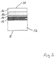
- FIG 2 shows the structure of a module 5, as it is is shown in Figure 1.
- Module 5 has one Base body 12 on which an insulation layer 13, a sensory layer 14, a further insulation layer 15 and on this a functional tribological Surface layer 16 are applied.
- the surface layer 16 forms the functional one Surface 11 of the module in the same way how the surface of the tool is used for shaping and therefore also subjected to appropriate forces becomes.
- the functional layer consists of Titanium nitride or chromium nitride and forms the conclusion of the layer system.
- the coating process for Production of the module is coordinated in this case that the entire system is made in two processes plus the necessary structuring the sensory level. Because of the layer system extreme mechanical and thermal loads the individual layers must act manufacturing processes used are designed that the entire layer structure is a layer technology Represents unit that is both material specific is also optimized morphologically.
- the sensory layer 14 can advantageously be structured to be piezoresistive and / or piezoelectric layer and the Generation of pressure and / or temperature-related measurements serves.
- FIG. 3 shows a stamp 20 with a sensor module 5, with the sensor module 5 being pressurized Surface of the stamp 20 is introduced.
- this stamp 20 is on pressed a workpiece 21 that over a die 22nd is arranged. In this case it is by means of Module 5 possible, the exact pressure and force ratios on the stamp surface of the stamp 20 to capture.
- FIG. 3B shows a section of the main stress zone of such a stamp, here the Section was taken, which contains the module 5.
- Wear sensors 23, 23 'and in the middle of these Temperature sensor 4 arranged.
- Figure 4 shows another example of a tool 1, which has a bore 2 for receiving a sensor module 5 has.
- the sensor module 5 has a cylindrical one Form and closes with its surface 11 form-fitting with the surface 10 of the tool 1.
- the hole 2 is through the entire tool out, so that the module 5 on the back as Contact opening 17 serving bore 2 with electrical Energy supplied and the measured values from the Module can be derived to an evaluation unit.
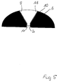
- Figure 5 shows another example of a tool 1, which, however, has a curved surface 10 here.
- a hole 2 is made which has a conical Cross section and also extends to the back of tool 1 continues.
- a sensor module 5 which is an adapted has a conical shape and its surface 11 in the same way as the surface 10 of the tool 1 is curved.
- module 5 on the back via as a contact opening 17 made hole 2 to contact the Supply sensors in module 5 and their energy Derive measured values to the outside.
Landscapes
- Engineering & Computer Science (AREA)
- Mechanical Engineering (AREA)
- Chemical & Material Sciences (AREA)
- Analytical Chemistry (AREA)
- Physics & Mathematics (AREA)
- General Physics & Mathematics (AREA)
- Cutting Tools, Boring Holders, And Turrets (AREA)
- Moulds For Moulding Plastics Or The Like (AREA)
- Pens And Brushes (AREA)
- Adornments (AREA)
Applications Claiming Priority (2)
| Application Number | Priority Date | Filing Date | Title |
|---|---|---|---|
| DE19925458 | 1999-06-02 | ||
| DE19925458A DE19925458C2 (de) | 1999-06-02 | 1999-06-02 | Herstellungsverfahren für Umform-, Stanz- und Spritzgußwerkzeuge |
Publications (3)
| Publication Number | Publication Date |
|---|---|
| EP1057586A2 true EP1057586A2 (fr) | 2000-12-06 |
| EP1057586A3 EP1057586A3 (fr) | 2001-01-03 |
| EP1057586B1 EP1057586B1 (fr) | 2003-04-23 |
Family
ID=7910135
Family Applications (1)
| Application Number | Title | Priority Date | Filing Date |
|---|---|---|---|
| EP00111200A Expired - Lifetime EP1057586B1 (fr) | 1999-06-02 | 2000-05-24 | Outil de formage, poinçonnage ou moulage par injection |
Country Status (3)
| Country | Link |
|---|---|
| EP (1) | EP1057586B1 (fr) |
| AT (1) | ATE238132T1 (fr) |
| DE (2) | DE19925458C2 (fr) |
Cited By (15)
| Publication number | Priority date | Publication date | Assignee | Title |
|---|---|---|---|---|
| WO2002054031A1 (fr) * | 1999-11-10 | 2002-07-11 | Fraunhofer-Gesellschaft zur Förderung der angewandten Forschung e.V. | Capteur servant a detecter l'etat de grandeurs nominales au niveau de composants mecaniques par utilisation de couches de carbone amorphes ayant des proprietes piezoresistives |
| EP1084806A3 (fr) * | 1999-09-17 | 2004-01-28 | Heidelberger Druckmaschinen Aktiengesellschaft | Système d'identification des outils de coupe pour une presse d'estampage |
| WO2004025234A1 (fr) * | 2002-09-10 | 2004-03-25 | Fraunhofer Gesellschaft zur Förderung der angewandten Forschung e.V. | Utilisation d'une couche de carbone de type diamant |
| WO2004067225A1 (fr) * | 2003-01-29 | 2004-08-12 | Fraunhofer-Gesellschaft zur Förderung der angewandten Forschung e.V. | Dispositif et procede pour determiner la sollicitation subie par un outil au moyen de capteurs a couche mince |
| DE10345299B3 (de) * | 2003-09-30 | 2005-07-21 | Giese, Erhard, Dr. | Druck/Temperatur-Sensor |
| US7010898B2 (en) | 2001-06-20 | 2006-03-14 | Convenience Food Systems Wallau Gmbh & Co. Kg | Tool with a sensor chip |
| WO2010135011A1 (fr) * | 2009-05-21 | 2010-11-25 | Siemens Energy, Inc. | Capteur pour quantifier une usure par réduction croissante sur une surface |
| WO2011009223A1 (fr) | 2009-07-22 | 2011-01-27 | Kistler Holding Ag | Module dassemblage électromécanique à capteur de force |
| DE102010001144A1 (de) * | 2010-01-22 | 2011-07-28 | Fraunhofer-Gesellschaft zur Förderung der angewandten Forschung e.V., 80686 | Mechanisches Verbindungsbauteil und Verfahren zur drahtlosen Erfassung einer mechanischen Belastung |
| EP2586587A1 (fr) * | 2011-10-28 | 2013-05-01 | Gerresheimer Regensburg GmbH | Dispositif et procédé de fabrication d'un objet au moyen d'un outil de moulage par injection |
| DE102012005555B3 (de) * | 2012-03-21 | 2013-08-22 | Audi Ag | Messplatte mit Sensoren |
| EP2928682B1 (fr) * | 2012-12-04 | 2018-05-30 | MARPOSS Monitoring Solutions GmbH | Dispositif d'estampage pourvu d'un capteur et procédé de transmission d'un signal du capteur |
| AT520955A1 (de) * | 2018-01-18 | 2019-09-15 | Engel Austria Gmbh | Messvorrichtung zur Messung des Abstands zweier ausgewählter Punkte |
| CN112203836A (zh) * | 2018-04-05 | 2021-01-08 | 百超激光有限公司 | 用于机床的构件、机床和用于识别磨损的方法 |
| DE102005033213B4 (de) * | 2004-07-23 | 2021-07-08 | The Minster Machine Co. | Schwingungsstärkeüberwacher für ein Pressengesenk sowie Presse mit einem Gesenksystem |
Families Citing this family (10)
| Publication number | Priority date | Publication date | Assignee | Title |
|---|---|---|---|---|
| DE10300630B4 (de) * | 2003-01-10 | 2005-03-24 | Daimlerchrysler Ag | Formpresseinrichtung |
| GB2406817B (en) * | 2003-01-10 | 2005-06-15 | Daimler Chrysler Ag | Moulding device |
| DE102004045783B4 (de) | 2004-09-21 | 2019-09-12 | Peter Schöberl | Thermoformwerkzeug |
| DE102009044838A1 (de) * | 2009-12-09 | 2011-06-16 | Karlsruher Institut für Technologie | Metastabilisiertes, nanostabilisiertes Material und Verfahren zu dessen Herstellung |
| DE102009057765A1 (de) * | 2009-12-10 | 2011-06-16 | Fraunhofer-Gesellschaft zur Förderung der angewandten Forschung e.V. | Signalführungsvorrichtung und Sensor mit einer solchen |
| DE102012022113A1 (de) * | 2012-11-13 | 2014-06-05 | Oerlikon Trading Ag, Trübbach | Piezoelektrische Kraftmessvorrichtung mit integrierten Verschleissschutz- und Gleiteigenschaften |
| DE102016204796A1 (de) * | 2016-03-23 | 2017-09-28 | Fraunhofer-Gesellschaft zur Förderung der angewandten Forschung e.V. | Messelement zur oberflächennahen Messung von physikalischen Größen, insbesondere von Temperaturen, in einer zumindest teilweise umschlossenen Kavität |
| JPWO2021192685A1 (fr) * | 2020-03-27 | 2021-09-30 | ||
| DE102021108310A1 (de) * | 2021-04-01 | 2022-10-06 | Lisa Dräxlmaier GmbH | Stanzvorrichtung |
| DE102022124171B3 (de) * | 2022-09-21 | 2023-12-28 | Dr. Ing. H.C. F. Porsche Aktiengesellschaft | Verfahren zur Ermittlung einer Druckverteilung einer Formwerkzeugeinrichtung sowie Verbundblechbauteil und Blechbauteil |
Family Cites Families (7)
| Publication number | Priority date | Publication date | Assignee | Title |
|---|---|---|---|---|
| SE452911B (sv) * | 1984-07-06 | 1987-12-21 | Birger Alvelid | Forfarande for framstellning av tillstandsgivare for mekaniska komponenter, jemte dylika mekaniska komponenter |
| DE4034702A1 (de) * | 1990-10-31 | 1992-05-07 | Siemens Ag | Verfahren und vorrichtung zur pruefung der aktiven werkzeuge von gesenkbiegemaschinen, insbesondere von biegestempeln |
| GB9026034D0 (en) * | 1990-11-29 | 1991-01-16 | Rolls Royce Plc | A fluid temperature measuring device |
| DE4419393A1 (de) * | 1994-05-30 | 1995-12-07 | Fraunhofer Ges Forschung | Werkzeug für Umform- und Zerspanungsvorrichtungen und Verfahren zum Herstellen eines beschichteten Werkzeugs |
| TW295622B (fr) * | 1994-10-28 | 1997-01-11 | Komatsu Mfg Co Ltd | |
| JPH0929358A (ja) * | 1995-07-20 | 1997-02-04 | Sanyo Special Steel Co Ltd | 高精度形状制御プレス金型 |
| US5622069A (en) * | 1996-03-11 | 1997-04-22 | Oberg Industries, Inc. | Stamping die with attached plc |
-
1999
- 1999-06-02 DE DE19925458A patent/DE19925458C2/de not_active Expired - Fee Related
-
2000
- 2000-05-24 EP EP00111200A patent/EP1057586B1/fr not_active Expired - Lifetime
- 2000-05-24 AT AT00111200T patent/ATE238132T1/de not_active IP Right Cessation
- 2000-05-24 DE DE50001833T patent/DE50001833D1/de not_active Expired - Lifetime
Cited By (23)
| Publication number | Priority date | Publication date | Assignee | Title |
|---|---|---|---|---|
| EP1084806A3 (fr) * | 1999-09-17 | 2004-01-28 | Heidelberger Druckmaschinen Aktiengesellschaft | Système d'identification des outils de coupe pour une presse d'estampage |
| US7073390B2 (en) | 1999-11-10 | 2006-07-11 | Fraunhofer-Gesellschaft Zur Forderung Der Angewandten Froschung E.V. | Sensor for determining the state of parameters on mechanical components while using amorphous carbon layers having piezoresistive properties |
| WO2002054031A1 (fr) * | 1999-11-10 | 2002-07-11 | Fraunhofer-Gesellschaft zur Förderung der angewandten Forschung e.V. | Capteur servant a detecter l'etat de grandeurs nominales au niveau de composants mecaniques par utilisation de couches de carbone amorphes ayant des proprietes piezoresistives |
| US7010898B2 (en) | 2001-06-20 | 2006-03-14 | Convenience Food Systems Wallau Gmbh & Co. Kg | Tool with a sensor chip |
| WO2004025234A1 (fr) * | 2002-09-10 | 2004-03-25 | Fraunhofer Gesellschaft zur Förderung der angewandten Forschung e.V. | Utilisation d'une couche de carbone de type diamant |
| US8151623B2 (en) | 2002-09-23 | 2012-04-10 | Siemens Energy, Inc. | Sensor for quantifying widening reduction wear on a surface |
| WO2004067225A1 (fr) * | 2003-01-29 | 2004-08-12 | Fraunhofer-Gesellschaft zur Förderung der angewandten Forschung e.V. | Dispositif et procede pour determiner la sollicitation subie par un outil au moyen de capteurs a couche mince |
| DE10345299B3 (de) * | 2003-09-30 | 2005-07-21 | Giese, Erhard, Dr. | Druck/Temperatur-Sensor |
| DE102005033213B4 (de) * | 2004-07-23 | 2021-07-08 | The Minster Machine Co. | Schwingungsstärkeüberwacher für ein Pressengesenk sowie Presse mit einem Gesenksystem |
| WO2010135011A1 (fr) * | 2009-05-21 | 2010-11-25 | Siemens Energy, Inc. | Capteur pour quantifier une usure par réduction croissante sur une surface |
| US8733181B2 (en) | 2009-07-22 | 2014-05-27 | Kistler Holding Ag | Electromechanical joining module having a force transducer |
| CN102470496A (zh) * | 2009-07-22 | 2012-05-23 | 基斯特勒控股公司 | 具有力传感器的电子机械接口模块 |
| CH701524A1 (de) * | 2009-07-22 | 2011-01-31 | Kistler Holding Ag | Elektromechanisches Fügemodul mit Kraftaufnehmer. |
| CN102470496B (zh) * | 2009-07-22 | 2015-11-25 | 基斯特勒控股公司 | 具有力传感器的电子机械接口模块 |
| WO2011009223A1 (fr) | 2009-07-22 | 2011-01-27 | Kistler Holding Ag | Module dassemblage électromécanique à capteur de force |
| DE102010001144A1 (de) * | 2010-01-22 | 2011-07-28 | Fraunhofer-Gesellschaft zur Förderung der angewandten Forschung e.V., 80686 | Mechanisches Verbindungsbauteil und Verfahren zur drahtlosen Erfassung einer mechanischen Belastung |
| EP2586587A1 (fr) * | 2011-10-28 | 2013-05-01 | Gerresheimer Regensburg GmbH | Dispositif et procédé de fabrication d'un objet au moyen d'un outil de moulage par injection |
| DE102012005555B3 (de) * | 2012-03-21 | 2013-08-22 | Audi Ag | Messplatte mit Sensoren |
| EP2928682B1 (fr) * | 2012-12-04 | 2018-05-30 | MARPOSS Monitoring Solutions GmbH | Dispositif d'estampage pourvu d'un capteur et procédé de transmission d'un signal du capteur |
| AT520955A1 (de) * | 2018-01-18 | 2019-09-15 | Engel Austria Gmbh | Messvorrichtung zur Messung des Abstands zweier ausgewählter Punkte |
| AT520955B1 (de) * | 2018-01-18 | 2020-08-15 | Engel Austria Gmbh | Messvorrichtung zur Messung des Abstands zweier ausgewählter Punkte |
| US11016115B2 (en) | 2018-01-18 | 2021-05-25 | Engel Austria Gmbh | Measuring device for measuring the space of two selected points on a shaping machine or handling apparatus |
| CN112203836A (zh) * | 2018-04-05 | 2021-01-08 | 百超激光有限公司 | 用于机床的构件、机床和用于识别磨损的方法 |
Also Published As
| Publication number | Publication date |
|---|---|
| DE50001833D1 (de) | 2003-05-28 |
| ATE238132T1 (de) | 2003-05-15 |
| EP1057586B1 (fr) | 2003-04-23 |
| EP1057586A3 (fr) | 2001-01-03 |
| DE19925458C2 (de) | 2002-07-18 |
| DE19925458A1 (de) | 2000-12-14 |
Similar Documents
| Publication | Publication Date | Title |
|---|---|---|
| EP1057586B1 (fr) | Outil de formage, poinçonnage ou moulage par injection | |
| EP2013598B1 (fr) | Dispositif de mesure de force pour mesurer la force dans le cas d'actionneurs monolithiques, procédé de mesure d'une force et utilisation du dispositif de mesure de force | |
| DE10017572B4 (de) | Wälzlager mit fernabfragbaren Erfassungseinheiten | |
| DE19925460C2 (de) | Gleit- und/oder Wälz-Paarungen mit Dünnschichtsensorik | |
| DE102015100655A1 (de) | Linearführungseinrichtung für eine Vorschubachse einer Werkzeugmaschine | |
| EP3211396B1 (fr) | Capteur de mesure intégrale ou à résolution spatiale d'allongements sur la base de fibres de carbone déjà endommagées | |
| EP1678474A2 (fr) | Dispositif permettant de detecter les sollicitations subies par des parties structurales en composite a base de fibres | |
| DE102009060441A1 (de) | Sensorelement | |
| DE102009053043A1 (de) | Kraftmesszelle zur Messung der Einspritzkraft beim Spritzgießen | |
| DE10243095B4 (de) | Wälzlager mit intergrierter Zustandsmessung | |
| WO2011039566A1 (fr) | Dispositif de mesure permettant de détecter des déformations | |
| EP2473818A1 (fr) | Dispositif pour mesurer et/ou enregistrer des distances et des variations de distance et dispositif pour mesurer et/ou enregistrer des contraintes mécaniques | |
| DE19958903A1 (de) | Aktorintegrierter Kraftsensor | |
| EP1495298A1 (fr) | Dispositif pour le controle de raccords par liaison de force | |
| DE19620459B4 (de) | Halbleiter-Beschleunigungsmesser und Verfahren zur Bewertung der Eigenschaften eines Halbleiter-Beschleunigungsmessers | |
| EP1888293B1 (fr) | Element optique et procede pour collecter des parametres de faisceau avec un capteur de temperature realise sous forme de matrice de pixels | |
| DE102010054970B4 (de) | Vorrichtung zum Wandeln einer Dehnung und/oder Stauchung in ein elektrisches Signal, insbesondere Dehnungsmessfolie | |
| WO2011160794A1 (fr) | Capteur de force piézo-résistif | |
| DE102021005558B3 (de) | Messrolle zum Feststellen einer Eigenschaft eines über eine Messrolle geführten bandförmigen Guts sowie Verwendung einer solchen Messrolle | |
| WO2011039567A1 (fr) | Dispositif de mesure à résistance désaccordable | |
| DE102006007406B3 (de) | Schubmessbrücke und Verfahren zur messtechnischen Erfassung des Schubes von Triebwerken | |
| DE4309530A1 (de) | Vorrichtung für die dynamisch-mechanische Analyse | |
| DE102024211423A1 (de) | Werkzeugführungsleiste für ein führungsleistengestütztes Werkzeug | |
| DE102019208427A1 (de) | Kugelgelenk mit integrierter Kraftmessung und Verschleißerkennung | |
| DE102024112470A1 (de) | Sensorbasis für eine Sensoreinrichtung, Verfahren zum Herstellen einer Sensorbasis, Sensoreinrichtung zum Erfassen von Verformungen, Drehmomentmessanordnung und Getriebe |
Legal Events
| Date | Code | Title | Description |
|---|---|---|---|
| PUAI | Public reference made under article 153(3) epc to a published international application that has entered the european phase |
Free format text: ORIGINAL CODE: 0009012 |
|
| PUAL | Search report despatched |
Free format text: ORIGINAL CODE: 0009013 |
|
| AK | Designated contracting states |
Kind code of ref document: A2 Designated state(s): AT BE CH CY DE DK ES FI FR GB GR IE IT LI LU MC NL PT SE |
|
| AX | Request for extension of the european patent |
Free format text: AL;LT;LV;MK;RO;SI |
|
| AK | Designated contracting states |
Kind code of ref document: A3 Designated state(s): AT BE CH CY DE DK ES FI FR GB GR IE IT LI LU MC NL PT SE |
|
| AX | Request for extension of the european patent |
Free format text: AL;LT;LV;MK;RO;SI |
|
| 17P | Request for examination filed |
Effective date: 20010120 |
|
| AKX | Designation fees paid |
Free format text: AT BE CH CY DE DK ES FI FR GB GR IE IT LI LU MC NL PT SE |
|
| GRAH | Despatch of communication of intention to grant a patent |
Free format text: ORIGINAL CODE: EPIDOS IGRA |
|
| GRAH | Despatch of communication of intention to grant a patent |
Free format text: ORIGINAL CODE: EPIDOS IGRA |
|
| GRAA | (expected) grant |
Free format text: ORIGINAL CODE: 0009210 |
|
| AK | Designated contracting states |
Designated state(s): AT BE CH CY DE DK ES FI FR GB GR IE IT LI LU MC NL PT SE |
|
| PG25 | Lapsed in a contracting state [announced via postgrant information from national office to epo] |
Ref country code: FI Free format text: LAPSE BECAUSE OF FAILURE TO SUBMIT A TRANSLATION OF THE DESCRIPTION OR TO PAY THE FEE WITHIN THE PRESCRIBED TIME-LIMIT Effective date: 20030423 Ref country code: IE Free format text: LAPSE BECAUSE OF NON-PAYMENT OF DUE FEES Effective date: 20030423 Ref country code: NL Free format text: LAPSE BECAUSE OF FAILURE TO SUBMIT A TRANSLATION OF THE DESCRIPTION OR TO PAY THE FEE WITHIN THE PRESCRIBED TIME-LIMIT Effective date: 20030423 |
|
| REG | Reference to a national code |
Ref country code: GB Ref legal event code: FG4D Free format text: NOT ENGLISH |
|
| REG | Reference to a national code |
Ref country code: CH Ref legal event code: EP |
|
| PGFP | Annual fee paid to national office [announced via postgrant information from national office to epo] |
Ref country code: AT Payment date: 20030523 Year of fee payment: 4 |
|
| PG25 | Lapsed in a contracting state [announced via postgrant information from national office to epo] |
Ref country code: LU Free format text: LAPSE BECAUSE OF NON-PAYMENT OF DUE FEES Effective date: 20030524 Ref country code: CY Free format text: LAPSE BECAUSE OF FAILURE TO SUBMIT A TRANSLATION OF THE DESCRIPTION OR TO PAY THE FEE WITHIN THE PRESCRIBED TIME-LIMIT Effective date: 20030524 |
|
| REF | Corresponds to: |
Ref document number: 50001833 Country of ref document: DE Date of ref document: 20030528 Kind code of ref document: P |
|
| REG | Reference to a national code |
Ref country code: IE Ref legal event code: FG4D Free format text: GERMAN |
|
| PG25 | Lapsed in a contracting state [announced via postgrant information from national office to epo] |
Ref country code: BE Free format text: LAPSE BECAUSE OF NON-PAYMENT OF DUE FEES Effective date: 20030531 Ref country code: MC Free format text: LAPSE BECAUSE OF NON-PAYMENT OF DUE FEES Effective date: 20030531 |
|
| PG25 | Lapsed in a contracting state [announced via postgrant information from national office to epo] |
Ref country code: GR Free format text: LAPSE BECAUSE OF FAILURE TO SUBMIT A TRANSLATION OF THE DESCRIPTION OR TO PAY THE FEE WITHIN THE PRESCRIBED TIME-LIMIT Effective date: 20030723 Ref country code: SE Free format text: LAPSE BECAUSE OF FAILURE TO SUBMIT A TRANSLATION OF THE DESCRIPTION OR TO PAY THE FEE WITHIN THE PRESCRIBED TIME-LIMIT Effective date: 20030723 Ref country code: PT Free format text: LAPSE BECAUSE OF FAILURE TO SUBMIT A TRANSLATION OF THE DESCRIPTION OR TO PAY THE FEE WITHIN THE PRESCRIBED TIME-LIMIT Effective date: 20030723 Ref country code: DK Free format text: LAPSE BECAUSE OF FAILURE TO SUBMIT A TRANSLATION OF THE DESCRIPTION OR TO PAY THE FEE WITHIN THE PRESCRIBED TIME-LIMIT Effective date: 20030723 |
|
| GBT | Gb: translation of ep patent filed (gb section 77(6)(a)/1977) | ||
| NLV1 | Nl: lapsed or annulled due to failure to fulfill the requirements of art. 29p and 29m of the patents act | ||
| PG25 | Lapsed in a contracting state [announced via postgrant information from national office to epo] |
Ref country code: ES Free format text: LAPSE BECAUSE OF FAILURE TO SUBMIT A TRANSLATION OF THE DESCRIPTION OR TO PAY THE FEE WITHIN THE PRESCRIBED TIME-LIMIT Effective date: 20031030 |
|
| RAP2 | Party data changed (patent owner data changed or rights of a patent transferred) |
Owner name: FRAUNHOFER-GESELLSCHAFT ZUR FOERDERUNG DERANGEWAND |
|
| REG | Reference to a national code |
Ref country code: IE Ref legal event code: FD4D Ref document number: 1057586E Country of ref document: IE |
|
| BERE | Be: lapsed |
Owner name: *FRAUNHOFER-GESELLSCHAFT ZUR FORDERUNG DER ANGEWAN Effective date: 20030531 |
|
| ET | Fr: translation filed | ||
| PLBE | No opposition filed within time limit |
Free format text: ORIGINAL CODE: 0009261 |
|
| STAA | Information on the status of an ep patent application or granted ep patent |
Free format text: STATUS: NO OPPOSITION FILED WITHIN TIME LIMIT |
|
| 26N | No opposition filed |
Effective date: 20040126 |
|
| PG25 | Lapsed in a contracting state [announced via postgrant information from national office to epo] |
Ref country code: AT Free format text: LAPSE BECAUSE OF NON-PAYMENT OF DUE FEES Effective date: 20040524 |
|
| PG25 | Lapsed in a contracting state [announced via postgrant information from national office to epo] |
Ref country code: LI Free format text: LAPSE BECAUSE OF NON-PAYMENT OF DUE FEES Effective date: 20040531 Ref country code: CH Free format text: LAPSE BECAUSE OF NON-PAYMENT OF DUE FEES Effective date: 20040531 |
|
| REG | Reference to a national code |
Ref country code: CH Ref legal event code: PL |
|
| PGFP | Annual fee paid to national office [announced via postgrant information from national office to epo] |
Ref country code: GB Payment date: 20120522 Year of fee payment: 13 Ref country code: FR Payment date: 20120608 Year of fee payment: 13 |
|
| PGFP | Annual fee paid to national office [announced via postgrant information from national office to epo] |
Ref country code: IT Payment date: 20120522 Year of fee payment: 13 |
|
| GBPC | Gb: european patent ceased through non-payment of renewal fee |
Effective date: 20130524 |
|
| PG25 | Lapsed in a contracting state [announced via postgrant information from national office to epo] |
Ref country code: IT Free format text: LAPSE BECAUSE OF NON-PAYMENT OF DUE FEES Effective date: 20130524 |
|
| REG | Reference to a national code |
Ref country code: FR Ref legal event code: ST Effective date: 20140131 |
|
| PG25 | Lapsed in a contracting state [announced via postgrant information from national office to epo] |
Ref country code: GB Free format text: LAPSE BECAUSE OF NON-PAYMENT OF DUE FEES Effective date: 20130524 |
|
| PG25 | Lapsed in a contracting state [announced via postgrant information from national office to epo] |
Ref country code: FR Free format text: LAPSE BECAUSE OF NON-PAYMENT OF DUE FEES Effective date: 20130531 |
|
| PGFP | Annual fee paid to national office [announced via postgrant information from national office to epo] |
Ref country code: DE Payment date: 20140521 Year of fee payment: 15 |
|
| REG | Reference to a national code |
Ref country code: DE Ref legal event code: R119 Ref document number: 50001833 Country of ref document: DE |
|
| PG25 | Lapsed in a contracting state [announced via postgrant information from national office to epo] |
Ref country code: DE Free format text: LAPSE BECAUSE OF NON-PAYMENT OF DUE FEES Effective date: 20151201 |