EP2586587A1 - Dispositif et procédé de fabrication d'un objet au moyen d'un outil de moulage par injection - Google Patents
Dispositif et procédé de fabrication d'un objet au moyen d'un outil de moulage par injection Download PDFInfo
- Publication number
- EP2586587A1 EP2586587A1 EP12184462.5A EP12184462A EP2586587A1 EP 2586587 A1 EP2586587 A1 EP 2586587A1 EP 12184462 A EP12184462 A EP 12184462A EP 2586587 A1 EP2586587 A1 EP 2586587A1
- Authority
- EP
- European Patent Office
- Prior art keywords
- receiving
- component
- detection device
- detection
- receiving device
- Prior art date
- Legal status (The legal status is an assumption and is not a legal conclusion. Google has not performed a legal analysis and makes no representation as to the accuracy of the status listed.)
- Granted
Links
Images


Classifications
-
- B—PERFORMING OPERATIONS; TRANSPORTING
- B29—WORKING OF PLASTICS; WORKING OF SUBSTANCES IN A PLASTIC STATE IN GENERAL
- B29C—SHAPING OR JOINING OF PLASTICS; SHAPING OF MATERIAL IN A PLASTIC STATE, NOT OTHERWISE PROVIDED FOR; AFTER-TREATMENT OF THE SHAPED PRODUCTS, e.g. REPAIRING
- B29C45/00—Injection moulding, i.e. forcing the required volume of moulding material through a nozzle into a closed mould; Apparatus therefor
- B29C45/14—Injection moulding, i.e. forcing the required volume of moulding material through a nozzle into a closed mould; Apparatus therefor incorporating preformed parts or layers, e.g. injection moulding around inserts or for coating articles
- B29C45/14065—Positioning or centering articles in the mould
-
- B—PERFORMING OPERATIONS; TRANSPORTING
- B29—WORKING OF PLASTICS; WORKING OF SUBSTANCES IN A PLASTIC STATE IN GENERAL
- B29C—SHAPING OR JOINING OF PLASTICS; SHAPING OF MATERIAL IN A PLASTIC STATE, NOT OTHERWISE PROVIDED FOR; AFTER-TREATMENT OF THE SHAPED PRODUCTS, e.g. REPAIRING
- B29C45/00—Injection moulding, i.e. forcing the required volume of moulding material through a nozzle into a closed mould; Apparatus therefor
- B29C45/17—Component parts, details or accessories; Auxiliary operations
- B29C45/76—Measuring, controlling or regulating
- B29C45/768—Detecting defective moulding conditions
-
- B—PERFORMING OPERATIONS; TRANSPORTING
- B29—WORKING OF PLASTICS; WORKING OF SUBSTANCES IN A PLASTIC STATE IN GENERAL
- B29C—SHAPING OR JOINING OF PLASTICS; SHAPING OF MATERIAL IN A PLASTIC STATE, NOT OTHERWISE PROVIDED FOR; AFTER-TREATMENT OF THE SHAPED PRODUCTS, e.g. REPAIRING
- B29C2945/00—Indexing scheme relating to injection moulding, i.e. forcing the required volume of moulding material through a nozzle into a closed mould
- B29C2945/76—Measuring, controlling or regulating
- B29C2945/76003—Measured parameter
- B29C2945/76083—Position
-
- B—PERFORMING OPERATIONS; TRANSPORTING
- B29—WORKING OF PLASTICS; WORKING OF SUBSTANCES IN A PLASTIC STATE IN GENERAL
- B29C—SHAPING OR JOINING OF PLASTICS; SHAPING OF MATERIAL IN A PLASTIC STATE, NOT OTHERWISE PROVIDED FOR; AFTER-TREATMENT OF THE SHAPED PRODUCTS, e.g. REPAIRING
- B29C2945/00—Indexing scheme relating to injection moulding, i.e. forcing the required volume of moulding material through a nozzle into a closed mould
- B29C2945/76—Measuring, controlling or regulating
- B29C2945/76177—Location of measurement
- B29C2945/76254—Mould
- B29C2945/76257—Mould cavity
-
- B—PERFORMING OPERATIONS; TRANSPORTING
- B29—WORKING OF PLASTICS; WORKING OF SUBSTANCES IN A PLASTIC STATE IN GENERAL
- B29C—SHAPING OR JOINING OF PLASTICS; SHAPING OF MATERIAL IN A PLASTIC STATE, NOT OTHERWISE PROVIDED FOR; AFTER-TREATMENT OF THE SHAPED PRODUCTS, e.g. REPAIRING
- B29C2945/00—Indexing scheme relating to injection moulding, i.e. forcing the required volume of moulding material through a nozzle into a closed mould
- B29C2945/76—Measuring, controlling or regulating
- B29C2945/76177—Location of measurement
- B29C2945/76294—Inserts
-
- B—PERFORMING OPERATIONS; TRANSPORTING
- B29—WORKING OF PLASTICS; WORKING OF SUBSTANCES IN A PLASTIC STATE IN GENERAL
- B29K—INDEXING SCHEME ASSOCIATED WITH SUBCLASSES B29B, B29C OR B29D, RELATING TO MOULDING MATERIALS OR TO MATERIALS FOR MOULDS, REINFORCEMENTS, FILLERS OR PREFORMED PARTS, e.g. INSERTS
- B29K2705/00—Use of metals, their alloys or their compounds, for preformed parts, e.g. for inserts
-
- B—PERFORMING OPERATIONS; TRANSPORTING
- B29—WORKING OF PLASTICS; WORKING OF SUBSTANCES IN A PLASTIC STATE IN GENERAL
- B29L—INDEXING SCHEME ASSOCIATED WITH SUBCLASS B29C, RELATING TO PARTICULAR ARTICLES
- B29L2031/00—Other particular articles
- B29L2031/753—Medical equipment; Accessories therefor
- B29L2031/7544—Injection needles, syringes
Definitions
- the invention relates to an apparatus and a method for producing an article by means of injection molding. More particularly, the invention relates to an apparatus and method for making a lancet that can be used, for example, by a patient as a blood sampling lancing device for determining its blood glucose level.
- a device for producing a lancet In this device, a needle is inserted into a receiving device in a first part of the system. In a second part of the plant, the needle is injection-molded with a plastic. In a third part of the plant, the lancet produced in the second part of the plant is removed from the receiving device. In a fourth part of the plant, faulty lancets are sorted out and the defect-free lancets are transferred to a magazine.
- the correct function of the device is detected at least in the first and third parts of the installation by means of an optical detection device, for example a camera or a light barrier. The optical detection device checks, for example, by evaluating an image, whether the needles in the system part 1 are correct, so that they can be properly encapsulated in the system part 2.
- a needle usually has a very small diameter of less than 1 mm.
- the tip of the needle has an even smaller diameter.
- the device comprises at least one receiving device for receiving a component of the object in order to hold the component in a further position during production of the object, a loading device for loading the receiving device with the component, and a detecting device for detecting a position of the component on the receiving device.
- the detection device comprises a sensor surface which is attached to the receiving device.
- the device described above is very simple and can ensure trouble-free that the component is held on the receiving device only at the predetermined position. For example, as soon as a component touches the detection device, this is detected and the manufacturing process of the device can be stopped. In particular, it can be ensured that the placement device correctly equips the receiving device with the component.
- the detection device By carrying out the detection device with a sensor surface attached to the receiving device, the problems of optical sensors, such as reflections, reflections, etc., can be avoided.
- the device is due to the detection device significantly cheaper and less maintenance-prone than a device with a camera as a detection device, which includes protection devices and extensive software packages for capture and evaluation.
- the receiving device has at least one recess, on which the component can be received, wherein the detection device is arranged inside and / or outside the recess.
- the detection device is designed to detect whether a component is not held at the predetermined position on the receiving device.
- the detection device is designed to detect whether the placement device correctly equips the receiving device with the component, detects the area inside and / or outside the recess. In this way, virtually all types of misplaced components can be detected.
- the receiving device may have two contact surfaces for applying the component to the receiving device, wherein the detection device is configured to detect whether the component bears against the two contact surfaces.
- the detection device is a capacitive or inductive detection device or a piezo or pressure sensor or an ultrasonic sensor.
- the detection device is a thin-film sensor.
- the device may also be a control device for controlling the device on the basis of a detection result of the detection device.
- the device may comprise a plurality of receiving devices, which are equipped by the loading device in a predetermined time.
- the object is also achieved by a method for producing an article by means of injection molding tool according to claim 10.
- the method comprises the steps of: loading, with a loading device, at least one receiving device with a component of the object, holding, with the receiving device, the component at a predetermined position, and detecting, with a detecting device, a position of the component on the receiving device, wherein the Detection device comprises a sensor surface which is attached to the receiving device.
- the invention is described below with reference to a device for producing a lancet. However, it is to be understood that the invention includes other devices for making another article, that is, not a lancet.
- Fig. 1 shows a device 1 for producing an article 5, in this case a lancet, according to a first embodiment.
- the device 1 has a first plant part 10, a second plant part 20, a third plant part 30 and a fourth plant part 40.
- the device 1 is described in more detail below.
- a lancet 5 produced by the device 1 is shown with a main body 6 and a needle 7.
- the needle 7 is fixed to the base body 6.
- the needle 7 is preferably made of stainless steel and has a diameter of less than 1 mm, for example 0.3 - 0.4 mm or even smaller.
- the tip of the needle 7 has an even smaller diameter.
- the lancet 5 can be used, for example, by a patient as a lancing device for blood sampling for the determination of its blood glucose value.
- the first part of the plant 10 serves Fig. 1 for positioning needles 7 at a predetermined position in which the needles 7 are to be held in the further production of the lancet 5.
- the second part of the plant 20 is used for injection molding.
- a plastic granules is melted and injected into a cavity, which is also called mold cavity or cavity and in which a needle 7 is located.
- the molded part of the mold can be removed.
- the plastic may in particular be PP, ABS, etc.
- the third piece of equipment 30 is used to remove the finished lancet 5 and possibly existing sprue.
- the fourth part of the plant 40 is used for bad part removal, ie for the rejection of defective lancets 5, and for the transfer of the finished lancets 5 to a magazine for storage or delivery of the lancet. 5
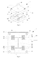
- Fig. 3 shows the device 1 at the first part of the plant 10 in more detail.
- the device 1 thus also comprises an upper tool part 50, a lower tool part 60 and a loading device 70.
- the loading device 70 is in Fig. 3 shown only very schematically and is used to load the lower tool part 60 with a component 7 of the article 5, in this case needles 7.
- the upper tool 50 has a plurality of center bores 51, in each of which a centering pin 61 of the lower tool part 60 can be inserted.
- the upper tool part 50 and the lower tool part 60 can be arranged in a fixed predetermined position to each other.
- a spray nozzle 80 for spraying plastic in receiving devices 90 is provided on the upper tool 50.
- a plurality of receiving devices 90 are arranged.
- the receiving devices 90 are connected to a flow channel 100, in which liquid plastic can flow between the receiving devices 90 in the second system part 20.
- On one of the receiving devices 90 two mispositioned needles 7 are shown.
- Fig. 4 and Fig. 5 show the tool lower part 60 in more detail.
- a detection device 110 is mounted at each of the receptacles 90.
- the detection device 110 is a thin-film sensor or thin-film sensor which operates capacitively or inductively or may be a piezo or pressure sensor or an ultrasonic sensor.
- Each detector 110 is in Fig. 4 and Fig. 5 marked with diamonds.
- Each detection device 110 is arranged on a receiving device 90 in such a way that a needle 7, which is not correctly arranged in the receiving device 90 at the predetermined position provided for it, that is in the wrong position, is detected.
- Each detection device 110 has at least one sensor surface, which is attached to the receiving device 90. In the figures, the detection device 110 is each shown with only one sensor surface, so that the sensor surface is also designated by the reference numeral 110.
- the detection devices 110 are each connected to a signal cable 120 with a control device 130. For the sake of clarity, is in Fig. 4 only one of the detection devices 110, a signal cable 120 is shown.
- the detection device 110 Detects one of the detection devices 110 that a needle 7 is not at the intended, so they are correct, position, as in the receiving device 90 in the lower left quarter of the lower tool part 60 in Fig. 4 , and even better in Fig. 5 1, the detection device 110 outputs a signal to the control device 130 via the signal cable 120. It is signaled that a component 7, that is a needle 7, is not held at the predetermined position on the receiving device. If no wrong or mispositioned needle 7 is detected, the detection device 110 outputs no signal to the control device 190. When the controller 130 receives a signal from the detector 110, it stops the device 1 to allow the misplaced needle 7 to be removed.
- Fig. 6 the arrangement of the detection device 110 is shown better on the receiving device 90.
- a needle 7 is correctly received in the receiving device 90 and thus correctly positioned.
- the correctly positioned needle 7 rests on two support members 91 which support the needle 7 at the correct, more precisely predetermined position.
- the support members 91 are designed as pins or bolts, which are spaced from each other in a recess 92 of the receiving device 90 are arranged.
- the needle 7 also abuts contact surfaces 93, which adjoin the depression 92.
- a correctly positioned needle 7 protrudes slightly beyond the recess 92 both at its tip and at its end and into the contact surfaces 93 arranged there.
- the contact surfaces 93 are thus arranged on the narrow sides of the rectangular recess 92. In this case, preferably all functions of the device 1 are stopped.
- Fig. 7 shows the arrangement of the detection device 110 in the region of the recess 92 and the contact surface or recesses 93 in a sectional view even better.
- the contact surfaces 93 are designed as recesses in the receiving device 90.
- the recess of the contact surface 93 has a smaller depth than the depth of the recess 92.
- the bolts 91 each have a notch 94, in which the needle 7 is inserted.
- the needle 7 is therefore at two points, namely the bolt 91 and more particularly their notches 94.
- the needle 7 is pressed lightly against a stop in the contact surfaces 93.
- the needle 7 abuts against the abutment surfaces 93, which may also be referred to as two points on which the needle 7 abuts.
- the detection device 110 extends to the edge of the contact surfaces or recesses 93 and to the edge of the recess 92 zoom. The latter is better in Fig. 6 shown.
- the detection device 110 is arranged outside the recess 92, in other words arranged around the recess 92.
- the detection device 110 is also arranged outside the contact surfaces 93, in other words arranged around the contact surfaces 93 around. There is no detection device 110 in the recess 92 and on the contact surfaces 93 or their recess in the receiving device 90.
- the mispositioned needles 7 may be detected by the detector 110 as previously described.
- the detection device 110 thus detects whether a component 7, ie a needle 7, is not held at the predetermined position on the receiving device 90. It can also be detected on the entire lower tool part 50, whether a component 7, that is, a needle 7, is not held at the predetermined position. Here it is checked in particular whether the loading device 70, the receiving device 90 properly equipped.
- Fig. 8 shows an enlarged partial view of a device 2 according to a second embodiment.
- the device 2 is largely constructed in the same way as the device 1 of the first embodiment. Therefore, the differences between the first and second embodiments will be described below mainly.
- Fig. 8 is a needle 7 correctly positioned in the receiving device 90.
- the detection device 110 is disposed outside the recess 92, in other words around the recess 92.
- the detection device 110 is also arranged outside the contact surfaces 93, in other words arranged around the contact surfaces 93 around.
- a detection device 111 is disposed within the recess 92. The detection device 111 is connected to the detection device 110, even if this is in Fig. 8 not shown.
- needle 7 can be detected, which are positioned incorrectly in the recess 92.
- the controller 130 when receiving a signal from the detector 110, may stop the device 2 to allow the misplaced needle 7 to be removed.
- the detection device 110 thus detects whether a component 7, ie a needle 7, is not held at the predetermined position on the receiving device.
- it is checked whether the loading device 70, the receiving device 90 correctly equipped.
- the detection device 111 may also check before insertion of the receiving devices 90 with needles 7, if all receiving devices 90 are free. That is, whether in a previous production of articles 5 at the plant part 3, all finished objects 5 were removed from the receiving devices 90.
- the control device 130 receives a signal from the detection device 111 that not all the receptacles 90 are free, it stops the device 2 so that the receptacle (s) 90 can be emptied.
- the detection device 110 can additionally be used to detect whether manufacturing residues project beyond the recess 92.
- the detection device 111 can detect whether a component 7, that is, a needle 7, is not held at the predetermined position on the receiving device.
- it is checked with the detection device 111 on the one hand, whether the loading device 70, the receiving device 90 properly equipped.
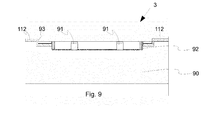
- Fig. 9 shows an enlarged partial sectional view of a device 3 according to a third embodiment.
- the device 3 is largely constructed in the same way as the device 1 of the first embodiment. Therefore, the differences between the first embodiment and the present embodiment will be described below mainly.
- a detection device 112 is also attached to the contact surfaces 93.
- the detection device 112 extends in the area of the contact surfaces 93 to the edge of Well 92 approach.
- no detection device is arranged in the depression 92.
- the detector 112 is therefore not present at the two points where the needle 7 rests, namely the notches 94 of the bolts 91. In addition, no detection device is present in the recess 92.
- the detection device 112 can also be used to reliably detect whether the needle 7 is correctly positioned on the receiving device 90. If the needle 7 is arranged in the predetermined position, the needle 7 is detected on both contact surfaces 93.
- the detection device 11 also detect mispositioned needles 7 on the receiving device 90.
- the detecting device 112 of this embodiment can also detect whether a component 7, that is, a needle 7, is not held at the predetermined position on the receiving device. Here, it is checked with the detection device 110 on the one hand, whether the loading device 70, the receiving device 90 properly equipped. On the other hand, the detection device 112 can check whether all receiving device (s) 90 are emptied before being equipped with the loading device 70.
- Such an embodiment represents a still further improvement in the detection of mispositioned needles and parts in the device 3 over the devices 1, 2 of the preceding embodiments. There are also the aforementioned advantages.
- the devices 1, 2, 3 of the described embodiments may also comprise fewer or more than four plant parts 10, 20, 30, 40.
- the devices 1, 2, 3 of the described embodiments can also produce more or fewer than four objects at a time.
- the receiving devices 90 are to be designed for receiving a corresponding number of components.
- only a receiving device 90 for receiving an object is conceivable.
- a device for producing lancets for example, 64 lancets can be manufactured simultaneously.
- Such a device may, for example, operate in a cycle in which the loading device 70 equips the receiving devices 90 with a plurality of needles in less than 10 seconds.
- the devices 1, 2, 3 of the embodiments are applicable to all devices in which components are received by a receiving device, in particular inserted into this.
- the devices 1, 2, 3 of the embodiments may, in place of an injection molding apparatus in particular also a punching, foaming, forming assembly device, etc. be.
- the respective detection device 110, 111, 112 instead of a connection of the detection devices 110, 111, 112 via a signal cable 120 to the control device 130, the respective detection device 110, 111, 112 also communicate wirelessly, ie wirelessly, with the control device 130.
- Detector 110 may not only be present on receptacle (s) 90. That is, the detection device 110 may be disposed on the entire surface of the tool lower part 60, which is associated with the tool top 50 and / or the mounting device 70.
- the detection device 111 may also be present on the two support elements 91 and detect whether the component 7 or the needle 7 is inserted into the indentations of the support elements 91.
- the detection device 111 may be present in particular in the notches 94 of the bolts 91.
- the detection device 110 can also be designed in such a way that the detection device 110 always outputs a signal to the control device 130 when the device is operated via the signal cable 120 when the function is correct.
- the signal of the detection device 110 is interrupted when a needle 7 is not in the predetermined position intended for them, such as in the receiving device 90 in the lower left quarter of the tool lower part 60 in Fig. 4 shown.
- the detection device 111 in the recess 92 and / or the detection device 112 can / can be carried out in the same way.
- the detection device 110 is preferably a three-layer thin-film sensor which has two layers each having a thickness of, for example, about 3 to 4 ⁇ m and preferably a chromium electrode which is arranged between the two sensor layers and has a thickness of, for example, about 200 nm.
- the chromium electrode may be sputtered onto one of the two layers.
- the chromium electrode can also be structured with a laser.
- One of the two layers may be a sensor layer, whereas the other layer may be an insulation and wear protection layer.
- the insulation and wear protection layer is preferably arranged as the uppermost layer on the receiving device 90.
- the detection device 111 and / or the detection device 112 are / is preferably carried out in the same way.
- two insulation and / or wear protection layers having a thickness of, for example, about 3 to 4 ⁇ m can be present in the detection device 110, between which a sensor layer having a thickness of, for example, about 200 nm is arranged.
- the detection device 111 and / or the detection device 112 are / is preferably carried out in the same way.
- the sensor layer is the sensor surface 110, which is attached to the receiving device 90 via the one of the two insulation and / or wear protection layers.
- the detection device 110 can be designed as a foil.
- the detection device 111 and / or the detection device 112 can / can be designed in the same way
- the detection device 110 can be vapor-deposited on the receiving device 90.
- a PVD method Physical Vapor Deposition
- the detection device 111 and / or the detection device 112 can / can be designed in the same way.
- the detection device 110 or only one of its sensor surfaces, also be glued to the receiving device 90.
- the detection device 110, or only one of its sensor surfaces also be welded to the receiving device 90.
- the detection device 110, or only one of its sensor surfaces may also be laminated to the receiving device 90.
Landscapes
- Engineering & Computer Science (AREA)
- Manufacturing & Machinery (AREA)
- Mechanical Engineering (AREA)
- Moulds For Moulding Plastics Or The Like (AREA)
- Measurement Of The Respiration, Hearing Ability, Form, And Blood Characteristics Of Living Organisms (AREA)
Applications Claiming Priority (1)
| Application Number | Priority Date | Filing Date | Title |
|---|---|---|---|
| DE102011054889.0A DE102011054889B4 (de) | 2011-10-28 | 2011-10-28 | Vorrichtung und Verfahren zur Herstellung eines Gegenstands mittels Spritzgießwerkzeug |
Publications (2)
| Publication Number | Publication Date |
|---|---|
| EP2586587A1 true EP2586587A1 (fr) | 2013-05-01 |
| EP2586587B1 EP2586587B1 (fr) | 2016-03-02 |
Family
ID=46980764
Family Applications (1)
| Application Number | Title | Priority Date | Filing Date |
|---|---|---|---|
| EP12184462.5A Active EP2586587B1 (fr) | 2011-10-28 | 2012-09-14 | Dispositif et procédé de fabrication d'un objet au moyen d'un outil de moulage par injection |
Country Status (3)
| Country | Link |
|---|---|
| EP (1) | EP2586587B1 (fr) |
| CN (1) | CN203110246U (fr) |
| DE (1) | DE102011054889B4 (fr) |
Cited By (2)
| Publication number | Priority date | Publication date | Assignee | Title |
|---|---|---|---|---|
| FR3042150A1 (fr) * | 2015-10-13 | 2017-04-14 | Plastic Omnium Cie | Controle acoustique d'un procede de surmoulage |
| WO2019106160A1 (fr) * | 2017-12-01 | 2019-06-06 | Bbg Gmbh & Co. Kg | Outil de moulage servant à enrober de mousse un disque et au moins une pièce d'insertion de tôle |
Families Citing this family (2)
| Publication number | Priority date | Publication date | Assignee | Title |
|---|---|---|---|---|
| CN109805940B (zh) * | 2017-11-20 | 2022-07-12 | 研能科技股份有限公司 | 血糖监测控制系统 |
| DE102019115097A1 (de) * | 2019-06-05 | 2020-12-10 | Cqlt Saargummi Technologies S.À.R.L. | Spritzgusswerkzeug |
Citations (6)
| Publication number | Priority date | Publication date | Assignee | Title |
|---|---|---|---|---|
| JPH02112415U (fr) * | 1989-02-23 | 1990-09-07 | ||
| JPH06219017A (ja) * | 1993-01-26 | 1994-08-09 | Minolta Camera Co Ltd | 画像形成装置 |
| JPH0878452A (ja) * | 1994-09-06 | 1996-03-22 | Hitachi Ltd | 樹脂封止装置 |
| EP1057586A2 (fr) * | 1999-06-02 | 2000-12-06 | Fraunhofer-Gesellschaft zur Förderung der angewandten Forschung e.V. | Outil de formage, poinçonnage ou moulage par injection |
| US20040115294A1 (en) * | 2002-12-17 | 2004-06-17 | Moran Michael W. | Machine having sensors for controlling molding operation |
| WO2011043383A1 (fr) * | 2009-10-07 | 2011-04-14 | 株式会社旭ポリスライダー | Lancette, procédé de fabrication de la lancette et moule pour le procédé |
Family Cites Families (2)
| Publication number | Priority date | Publication date | Assignee | Title |
|---|---|---|---|---|
| US3677680A (en) * | 1970-10-08 | 1972-07-18 | California Injection Molding C | Fluidic sensing for molding system |
| EP1897668A1 (fr) * | 2006-09-11 | 2008-03-12 | L&P Swiss Holding Company | Méthode et dispositif pour alimenter automatiquement des inserts à un moule et moule |
-
2011
- 2011-10-28 DE DE102011054889.0A patent/DE102011054889B4/de not_active Expired - Fee Related
-
2012
- 2012-09-14 EP EP12184462.5A patent/EP2586587B1/fr active Active
- 2012-10-17 CN CN2012205311785U patent/CN203110246U/zh not_active Expired - Lifetime
Patent Citations (6)
| Publication number | Priority date | Publication date | Assignee | Title |
|---|---|---|---|---|
| JPH02112415U (fr) * | 1989-02-23 | 1990-09-07 | ||
| JPH06219017A (ja) * | 1993-01-26 | 1994-08-09 | Minolta Camera Co Ltd | 画像形成装置 |
| JPH0878452A (ja) * | 1994-09-06 | 1996-03-22 | Hitachi Ltd | 樹脂封止装置 |
| EP1057586A2 (fr) * | 1999-06-02 | 2000-12-06 | Fraunhofer-Gesellschaft zur Förderung der angewandten Forschung e.V. | Outil de formage, poinçonnage ou moulage par injection |
| US20040115294A1 (en) * | 2002-12-17 | 2004-06-17 | Moran Michael W. | Machine having sensors for controlling molding operation |
| WO2011043383A1 (fr) * | 2009-10-07 | 2011-04-14 | 株式会社旭ポリスライダー | Lancette, procédé de fabrication de la lancette et moule pour le procédé |
Cited By (4)
| Publication number | Priority date | Publication date | Assignee | Title |
|---|---|---|---|---|
| FR3042150A1 (fr) * | 2015-10-13 | 2017-04-14 | Plastic Omnium Cie | Controle acoustique d'un procede de surmoulage |
| EP3156204A1 (fr) * | 2015-10-13 | 2017-04-19 | Compagnie Plastic Omnium | Contrôle acoustique d'un procédé de surmoulage |
| WO2019106160A1 (fr) * | 2017-12-01 | 2019-06-06 | Bbg Gmbh & Co. Kg | Outil de moulage servant à enrober de mousse un disque et au moins une pièce d'insertion de tôle |
| US11752672B2 (en) | 2017-12-01 | 2023-09-12 | Bbg Gmbh & Co. Kg | Moulding tool for foam overmolding a glass pane and at least one insert part |
Also Published As
| Publication number | Publication date |
|---|---|
| CN203110246U (zh) | 2013-08-07 |
| DE102011054889B4 (de) | 2019-03-14 |
| EP2586587B1 (fr) | 2016-03-02 |
| DE102011054889A1 (de) | 2013-05-02 |
Similar Documents
| Publication | Publication Date | Title |
|---|---|---|
| DE60107936T2 (de) | Vorrichtung und verfahren zur handhabung von ophthalmischen linsen | |
| EP2586587B1 (fr) | Dispositif et procédé de fabrication d'un objet au moyen d'un outil de moulage par injection | |
| EP1938944B1 (fr) | Procédé pour la fabrication d'un corps en matière plastique multicouche | |
| DE102017205095B3 (de) | Vorrichtung und Verfahren zum Entnehmen eines Werkstückteils aus einem Restwerkstück | |
| DE102015000618B4 (de) | Schließeinheit, Formgebungsmaschine und Verfahren zur Überwachung einer Schließeinheit | |
| DE102011103824A1 (de) | Fertigungseinrichtung und Verfahren zur Herstellung In-Mould-dekorierter Kunststoffformteile | |
| WO2013045013A1 (fr) | Seringue comportant un cylindre de seringue pourvu d'un codage et d'éléments de contrôle | |
| DE102018002734B4 (de) | Spritzgiesssystem und Spritzgiessverfahren | |
| EP3998093B1 (fr) | Dispositif médical pourvu de convertisseur appliqué de manière additive | |
| WO2023174645A1 (fr) | Procédé et dispositif de remplissage de récipients emboîtés | |
| EP3093115B1 (fr) | Dispositif de réception et procédé d'injection | |
| DE102022202597A1 (de) | Verfahren und Vorrichtung zum Befüllen genesteter Behälter | |
| WO2019175343A1 (fr) | Procédé pour la surveillance automatique de la distribution de colle d'une vanne à colle | |
| DE102016114586B4 (de) | Pulverzuführvorrichtung | |
| DE102012102008A1 (de) | Vorrichtung und Verfahren zum Herstellen von Kunststoffteilen | |
| BE1030746B1 (de) | Spritzgießvorrichtung und Spritzgießverfahren sowie Computerprogramm und computerlesbares Medium | |
| EP3946877B1 (fr) | Machine de moulage | |
| WO2005105584A1 (fr) | Dispositif pour delivrer une etiquette en un emplacement defini, et dispositif d'insertion d'une telle etiquette | |
| EP2579700A2 (fr) | Dispositif de support de composant avec un marquage apposé sur une paroi intérieure | |
| WO2024223744A1 (fr) | Technique d'entaillage pour préparer une pièce d'essai dans le cadre de la vérification de matériau | |
| EP4461503A1 (fr) | Procédé de fabrication d'un composant avec un dispositif de moulage par injection et dispositif de moulage par injection | |
| EP3722473B1 (fr) | Dispositif de préhension d'un dispositif destiné à l'introduction des éléments d'insertion dans un tricot | |
| EP4418241A2 (fr) | Élément en feuille, empilement d'éléments en feuille, produit en plastique et moule d'injection, et procédé de fabrication d'un élément en feuille et d'un produit en plastique | |
| DE202022003127U1 (de) | Vorrichtung zum Befüllen genesteter Behälter | |
| DE202022003128U1 (de) | Vorrichtung zum Befüllen genesteter Behälter |
Legal Events
| Date | Code | Title | Description |
|---|---|---|---|
| PUAI | Public reference made under article 153(3) epc to a published international application that has entered the european phase |
Free format text: ORIGINAL CODE: 0009012 |
|
| 17P | Request for examination filed |
Effective date: 20130301 |
|
| AK | Designated contracting states |
Kind code of ref document: A1 Designated state(s): AL AT BE BG CH CY CZ DE DK EE ES FI FR GB GR HR HU IE IS IT LI LT LU LV MC MK MT NL NO PL PT RO RS SE SI SK SM TR |
|
| AX | Request for extension of the european patent |
Extension state: BA ME |
|
| RBV | Designated contracting states (corrected) |
Designated state(s): AL AT BE BG CH CY CZ DE DK EE ES FI FR GB GR HR HU IE IS IT LI LT LU LV MC MK MT NL NO PL PT RO RS SE SI SK SM TR |
|
| GRAP | Despatch of communication of intention to grant a patent |
Free format text: ORIGINAL CODE: EPIDOSNIGR1 |
|
| INTG | Intention to grant announced |
Effective date: 20150911 |
|
| GRAS | Grant fee paid |
Free format text: ORIGINAL CODE: EPIDOSNIGR3 |
|
| GRAA | (expected) grant |
Free format text: ORIGINAL CODE: 0009210 |
|
| AK | Designated contracting states |
Kind code of ref document: B1 Designated state(s): AL AT BE BG CH CY CZ DE DK EE ES FI FR GB GR HR HU IE IS IT LI LT LU LV MC MK MT NL NO PL PT RO RS SE SI SK SM TR |
|
| REG | Reference to a national code |
Ref country code: GB Ref legal event code: FG4D Free format text: NOT ENGLISH |
|
| REG | Reference to a national code |
Ref country code: AT Ref legal event code: REF Ref document number: 777688 Country of ref document: AT Kind code of ref document: T Effective date: 20160315 Ref country code: CH Ref legal event code: EP |
|
| REG | Reference to a national code |
Ref country code: IE Ref legal event code: FG4D Free format text: LANGUAGE OF EP DOCUMENT: GERMAN |
|
| REG | Reference to a national code |
Ref country code: DE Ref legal event code: R096 Ref document number: 502012006101 Country of ref document: DE |
|
| REG | Reference to a national code |
Ref country code: NL Ref legal event code: MP Effective date: 20160302 |
|
| REG | Reference to a national code |
Ref country code: LT Ref legal event code: MG4D |
|
| PG25 | Lapsed in a contracting state [announced via postgrant information from national office to epo] |
Ref country code: FI Free format text: LAPSE BECAUSE OF FAILURE TO SUBMIT A TRANSLATION OF THE DESCRIPTION OR TO PAY THE FEE WITHIN THE PRESCRIBED TIME-LIMIT Effective date: 20160302 Ref country code: ES Free format text: LAPSE BECAUSE OF FAILURE TO SUBMIT A TRANSLATION OF THE DESCRIPTION OR TO PAY THE FEE WITHIN THE PRESCRIBED TIME-LIMIT Effective date: 20160302 Ref country code: NO Free format text: LAPSE BECAUSE OF FAILURE TO SUBMIT A TRANSLATION OF THE DESCRIPTION OR TO PAY THE FEE WITHIN THE PRESCRIBED TIME-LIMIT Effective date: 20160602 Ref country code: GR Free format text: LAPSE BECAUSE OF FAILURE TO SUBMIT A TRANSLATION OF THE DESCRIPTION OR TO PAY THE FEE WITHIN THE PRESCRIBED TIME-LIMIT Effective date: 20160603 Ref country code: HR Free format text: LAPSE BECAUSE OF FAILURE TO SUBMIT A TRANSLATION OF THE DESCRIPTION OR TO PAY THE FEE WITHIN THE PRESCRIBED TIME-LIMIT Effective date: 20160302 |
|
| PG25 | Lapsed in a contracting state [announced via postgrant information from national office to epo] |
Ref country code: PL Free format text: LAPSE BECAUSE OF FAILURE TO SUBMIT A TRANSLATION OF THE DESCRIPTION OR TO PAY THE FEE WITHIN THE PRESCRIBED TIME-LIMIT Effective date: 20160302 Ref country code: NL Free format text: LAPSE BECAUSE OF FAILURE TO SUBMIT A TRANSLATION OF THE DESCRIPTION OR TO PAY THE FEE WITHIN THE PRESCRIBED TIME-LIMIT Effective date: 20160302 Ref country code: LV Free format text: LAPSE BECAUSE OF FAILURE TO SUBMIT A TRANSLATION OF THE DESCRIPTION OR TO PAY THE FEE WITHIN THE PRESCRIBED TIME-LIMIT Effective date: 20160302 Ref country code: RS Free format text: LAPSE BECAUSE OF FAILURE TO SUBMIT A TRANSLATION OF THE DESCRIPTION OR TO PAY THE FEE WITHIN THE PRESCRIBED TIME-LIMIT Effective date: 20160302 Ref country code: SE Free format text: LAPSE BECAUSE OF FAILURE TO SUBMIT A TRANSLATION OF THE DESCRIPTION OR TO PAY THE FEE WITHIN THE PRESCRIBED TIME-LIMIT Effective date: 20160302 Ref country code: LT Free format text: LAPSE BECAUSE OF FAILURE TO SUBMIT A TRANSLATION OF THE DESCRIPTION OR TO PAY THE FEE WITHIN THE PRESCRIBED TIME-LIMIT Effective date: 20160302 |
|
| PG25 | Lapsed in a contracting state [announced via postgrant information from national office to epo] |
Ref country code: IS Free format text: LAPSE BECAUSE OF FAILURE TO SUBMIT A TRANSLATION OF THE DESCRIPTION OR TO PAY THE FEE WITHIN THE PRESCRIBED TIME-LIMIT Effective date: 20160702 Ref country code: EE Free format text: LAPSE BECAUSE OF FAILURE TO SUBMIT A TRANSLATION OF THE DESCRIPTION OR TO PAY THE FEE WITHIN THE PRESCRIBED TIME-LIMIT Effective date: 20160302 |
|
| REG | Reference to a national code |
Ref country code: FR Ref legal event code: PLFP Year of fee payment: 5 |
|
| PG25 | Lapsed in a contracting state [announced via postgrant information from national office to epo] |
Ref country code: CZ Free format text: LAPSE BECAUSE OF FAILURE TO SUBMIT A TRANSLATION OF THE DESCRIPTION OR TO PAY THE FEE WITHIN THE PRESCRIBED TIME-LIMIT Effective date: 20160302 Ref country code: RO Free format text: LAPSE BECAUSE OF FAILURE TO SUBMIT A TRANSLATION OF THE DESCRIPTION OR TO PAY THE FEE WITHIN THE PRESCRIBED TIME-LIMIT Effective date: 20160302 Ref country code: PT Free format text: LAPSE BECAUSE OF FAILURE TO SUBMIT A TRANSLATION OF THE DESCRIPTION OR TO PAY THE FEE WITHIN THE PRESCRIBED TIME-LIMIT Effective date: 20160704 Ref country code: SK Free format text: LAPSE BECAUSE OF FAILURE TO SUBMIT A TRANSLATION OF THE DESCRIPTION OR TO PAY THE FEE WITHIN THE PRESCRIBED TIME-LIMIT Effective date: 20160302 Ref country code: SM Free format text: LAPSE BECAUSE OF FAILURE TO SUBMIT A TRANSLATION OF THE DESCRIPTION OR TO PAY THE FEE WITHIN THE PRESCRIBED TIME-LIMIT Effective date: 20160302 |
|
| REG | Reference to a national code |
Ref country code: DE Ref legal event code: R097 Ref document number: 502012006101 Country of ref document: DE |
|
| PG25 | Lapsed in a contracting state [announced via postgrant information from national office to epo] |
Ref country code: IT Free format text: LAPSE BECAUSE OF FAILURE TO SUBMIT A TRANSLATION OF THE DESCRIPTION OR TO PAY THE FEE WITHIN THE PRESCRIBED TIME-LIMIT Effective date: 20160302 |
|
| PLBE | No opposition filed within time limit |
Free format text: ORIGINAL CODE: 0009261 |
|
| STAA | Information on the status of an ep patent application or granted ep patent |
Free format text: STATUS: NO OPPOSITION FILED WITHIN TIME LIMIT |
|
| PG25 | Lapsed in a contracting state [announced via postgrant information from national office to epo] |
Ref country code: DK Free format text: LAPSE BECAUSE OF FAILURE TO SUBMIT A TRANSLATION OF THE DESCRIPTION OR TO PAY THE FEE WITHIN THE PRESCRIBED TIME-LIMIT Effective date: 20160302 |
|
| 26N | No opposition filed |
Effective date: 20161205 |
|
| PG25 | Lapsed in a contracting state [announced via postgrant information from national office to epo] |
Ref country code: SI Free format text: LAPSE BECAUSE OF FAILURE TO SUBMIT A TRANSLATION OF THE DESCRIPTION OR TO PAY THE FEE WITHIN THE PRESCRIBED TIME-LIMIT Effective date: 20160302 Ref country code: BG Free format text: LAPSE BECAUSE OF FAILURE TO SUBMIT A TRANSLATION OF THE DESCRIPTION OR TO PAY THE FEE WITHIN THE PRESCRIBED TIME-LIMIT Effective date: 20160602 Ref country code: BE Free format text: LAPSE BECAUSE OF NON-PAYMENT OF DUE FEES Effective date: 20160930 |
|
| PG25 | Lapsed in a contracting state [announced via postgrant information from national office to epo] |
Ref country code: MC Free format text: LAPSE BECAUSE OF FAILURE TO SUBMIT A TRANSLATION OF THE DESCRIPTION OR TO PAY THE FEE WITHIN THE PRESCRIBED TIME-LIMIT Effective date: 20160302 |
|
| REG | Reference to a national code |
Ref country code: CH Ref legal event code: PL |
|
| REG | Reference to a national code |
Ref country code: IE Ref legal event code: MM4A |
|
| PG25 | Lapsed in a contracting state [announced via postgrant information from national office to epo] |
Ref country code: IE Free format text: LAPSE BECAUSE OF NON-PAYMENT OF DUE FEES Effective date: 20160914 Ref country code: CH Free format text: LAPSE BECAUSE OF NON-PAYMENT OF DUE FEES Effective date: 20160930 Ref country code: LI Free format text: LAPSE BECAUSE OF NON-PAYMENT OF DUE FEES Effective date: 20160930 |
|
| PG25 | Lapsed in a contracting state [announced via postgrant information from national office to epo] |
Ref country code: LU Free format text: LAPSE BECAUSE OF NON-PAYMENT OF DUE FEES Effective date: 20160914 |
|
| REG | Reference to a national code |
Ref country code: FR Ref legal event code: PLFP Year of fee payment: 6 |
|
| REG | Reference to a national code |
Ref country code: BE Ref legal event code: MM Effective date: 20160930 |
|
| PG25 | Lapsed in a contracting state [announced via postgrant information from national office to epo] |
Ref country code: CY Free format text: LAPSE BECAUSE OF FAILURE TO SUBMIT A TRANSLATION OF THE DESCRIPTION OR TO PAY THE FEE WITHIN THE PRESCRIBED TIME-LIMIT Effective date: 20160302 Ref country code: HU Free format text: LAPSE BECAUSE OF FAILURE TO SUBMIT A TRANSLATION OF THE DESCRIPTION OR TO PAY THE FEE WITHIN THE PRESCRIBED TIME-LIMIT; INVALID AB INITIO Effective date: 20120914 |
|
| PG25 | Lapsed in a contracting state [announced via postgrant information from national office to epo] |
Ref country code: TR Free format text: LAPSE BECAUSE OF FAILURE TO SUBMIT A TRANSLATION OF THE DESCRIPTION OR TO PAY THE FEE WITHIN THE PRESCRIBED TIME-LIMIT Effective date: 20160302 Ref country code: MK Free format text: LAPSE BECAUSE OF FAILURE TO SUBMIT A TRANSLATION OF THE DESCRIPTION OR TO PAY THE FEE WITHIN THE PRESCRIBED TIME-LIMIT Effective date: 20160302 Ref country code: MT Free format text: LAPSE BECAUSE OF FAILURE TO SUBMIT A TRANSLATION OF THE DESCRIPTION OR TO PAY THE FEE WITHIN THE PRESCRIBED TIME-LIMIT Effective date: 20160302 |
|
| REG | Reference to a national code |
Ref country code: FR Ref legal event code: PLFP Year of fee payment: 7 |
|
| PG25 | Lapsed in a contracting state [announced via postgrant information from national office to epo] |
Ref country code: AL Free format text: LAPSE BECAUSE OF FAILURE TO SUBMIT A TRANSLATION OF THE DESCRIPTION OR TO PAY THE FEE WITHIN THE PRESCRIBED TIME-LIMIT Effective date: 20160302 |
|
| REG | Reference to a national code |
Ref country code: AT Ref legal event code: MM01 Ref document number: 777688 Country of ref document: AT Kind code of ref document: T Effective date: 20170914 |
|
| PG25 | Lapsed in a contracting state [announced via postgrant information from national office to epo] |
Ref country code: AT Free format text: LAPSE BECAUSE OF NON-PAYMENT OF DUE FEES Effective date: 20170914 |
|
| P01 | Opt-out of the competence of the unified patent court (upc) registered |
Effective date: 20230530 |
|
| PGFP | Annual fee paid to national office [announced via postgrant information from national office to epo] |
Ref country code: DE Payment date: 20250919 Year of fee payment: 14 |
|
| PGFP | Annual fee paid to national office [announced via postgrant information from national office to epo] |
Ref country code: GB Payment date: 20250923 Year of fee payment: 14 |
|
| PGFP | Annual fee paid to national office [announced via postgrant information from national office to epo] |
Ref country code: FR Payment date: 20250924 Year of fee payment: 14 |