EP1057597A2 - Dispositif de fixation d'une plaque de coupe aux filets sur un cylindre de coupe - Google Patents
Dispositif de fixation d'une plaque de coupe aux filets sur un cylindre de coupe Download PDFInfo
- Publication number
- EP1057597A2 EP1057597A2 EP00107341A EP00107341A EP1057597A2 EP 1057597 A2 EP1057597 A2 EP 1057597A2 EP 00107341 A EP00107341 A EP 00107341A EP 00107341 A EP00107341 A EP 00107341A EP 1057597 A2 EP1057597 A2 EP 1057597A2
- Authority
- EP
- European Patent Office
- Prior art keywords
- knife
- body part
- foil
- base plate
- roller according
- Prior art date
- Legal status (The legal status is an assumption and is not a legal conclusion. Google has not performed a legal analysis and makes no representation as to the accuracy of the status listed.)
- Granted
Links
Images


Classifications
-
- B—PERFORMING OPERATIONS; TRANSPORTING
- B26—HAND CUTTING TOOLS; CUTTING; SEVERING
- B26D—CUTTING; DETAILS COMMON TO MACHINES FOR PERFORATING, PUNCHING, CUTTING-OUT, STAMPING-OUT OR SEVERING
- B26D7/00—Details of apparatus for cutting, cutting-out, stamping-out, punching, perforating, or severing by means other than cutting
- B26D7/26—Means for mounting or adjusting the cutting member; Means for adjusting the stroke of the cutting member
- B26D7/2628—Means for adjusting the position of the cutting member
-
- B—PERFORMING OPERATIONS; TRANSPORTING
- B26—HAND CUTTING TOOLS; CUTTING; SEVERING
- B26D—CUTTING; DETAILS COMMON TO MACHINES FOR PERFORATING, PUNCHING, CUTTING-OUT, STAMPING-OUT OR SEVERING
- B26D7/00—Details of apparatus for cutting, cutting-out, stamping-out, punching, perforating, or severing by means other than cutting
- B26D7/26—Means for mounting or adjusting the cutting member; Means for adjusting the stroke of the cutting member
- B26D7/2614—Means for mounting the cutting member
-
- B—PERFORMING OPERATIONS; TRANSPORTING
- B26—HAND CUTTING TOOLS; CUTTING; SEVERING
- B26D—CUTTING; DETAILS COMMON TO MACHINES FOR PERFORATING, PUNCHING, CUTTING-OUT, STAMPING-OUT OR SEVERING
- B26D7/00—Details of apparatus for cutting, cutting-out, stamping-out, punching, perforating, or severing by means other than cutting
- B26D7/26—Means for mounting or adjusting the cutting member; Means for adjusting the stroke of the cutting member
- B26D2007/2607—Means for mounting or adjusting the cutting member; Means for adjusting the stroke of the cutting member for mounting die cutters
-
- B—PERFORMING OPERATIONS; TRANSPORTING
- B26—HAND CUTTING TOOLS; CUTTING; SEVERING
- B26F—PERFORATING; PUNCHING; CUTTING-OUT; STAMPING-OUT; SEVERING BY MEANS OTHER THAN CUTTING
- B26F1/00—Perforating; Punching; Cutting-out; Stamping-out; Apparatus therefor
- B26F1/38—Cutting-out; Stamping-out
- B26F1/40—Cutting-out; Stamping-out using a press, e.g. of the ram type
- B26F1/42—Cutting-out; Stamping-out using a press, e.g. of the ram type having a pressure roller
-
- B—PERFORMING OPERATIONS; TRANSPORTING
- B26—HAND CUTTING TOOLS; CUTTING; SEVERING
- B26F—PERFORATING; PUNCHING; CUTTING-OUT; STAMPING-OUT; SEVERING BY MEANS OTHER THAN CUTTING
- B26F1/00—Perforating; Punching; Cutting-out; Stamping-out; Apparatus therefor
- B26F1/38—Cutting-out; Stamping-out
- B26F1/44—Cutters therefor; Dies therefor
-
- B—PERFORMING OPERATIONS; TRANSPORTING
- B31—MAKING ARTICLES OF PAPER, CARDBOARD OR MATERIAL WORKED IN A MANNER ANALOGOUS TO PAPER; WORKING PAPER, CARDBOARD OR MATERIAL WORKED IN A MANNER ANALOGOUS TO PAPER
- B31B—MAKING CONTAINERS OF PAPER, CARDBOARD OR MATERIAL WORKED IN A MANNER ANALOGOUS TO PAPER
- B31B2150/00—Flexible containers made from sheets or blanks, e.g. from flattened tubes
-
- B—PERFORMING OPERATIONS; TRANSPORTING
- B31—MAKING ARTICLES OF PAPER, CARDBOARD OR MATERIAL WORKED IN A MANNER ANALOGOUS TO PAPER; WORKING PAPER, CARDBOARD OR MATERIAL WORKED IN A MANNER ANALOGOUS TO PAPER
- B31B—MAKING CONTAINERS OF PAPER, CARDBOARD OR MATERIAL WORKED IN A MANNER ANALOGOUS TO PAPER
- B31B2160/00—Shape of flexible containers
- B31B2160/10—Shape of flexible containers rectangular and flat, i.e. without structural provision for thickness of contents
-
- B—PERFORMING OPERATIONS; TRANSPORTING
- B31—MAKING ARTICLES OF PAPER, CARDBOARD OR MATERIAL WORKED IN A MANNER ANALOGOUS TO PAPER; WORKING PAPER, CARDBOARD OR MATERIAL WORKED IN A MANNER ANALOGOUS TO PAPER
- B31B—MAKING CONTAINERS OF PAPER, CARDBOARD OR MATERIAL WORKED IN A MANNER ANALOGOUS TO PAPER
- B31B2170/00—Construction of flexible containers
-
- B—PERFORMING OPERATIONS; TRANSPORTING
- B31—MAKING ARTICLES OF PAPER, CARDBOARD OR MATERIAL WORKED IN A MANNER ANALOGOUS TO PAPER; WORKING PAPER, CARDBOARD OR MATERIAL WORKED IN A MANNER ANALOGOUS TO PAPER
- B31B—MAKING CONTAINERS OF PAPER, CARDBOARD OR MATERIAL WORKED IN A MANNER ANALOGOUS TO PAPER
- B31B70/00—Making flexible containers, e.g. envelopes or bags
- B31B70/74—Auxiliary operations
- B31B70/81—Forming or attaching accessories, e.g. opening devices, closures or tear strings
- B31B70/82—Forming or attaching windows
- B31B70/83—Cutting window openings
-
- Y—GENERAL TAGGING OF NEW TECHNOLOGICAL DEVELOPMENTS; GENERAL TAGGING OF CROSS-SECTIONAL TECHNOLOGIES SPANNING OVER SEVERAL SECTIONS OF THE IPC; TECHNICAL SUBJECTS COVERED BY FORMER USPC CROSS-REFERENCE ART COLLECTIONS [XRACs] AND DIGESTS
- Y10—TECHNICAL SUBJECTS COVERED BY FORMER USPC
- Y10T—TECHNICAL SUBJECTS COVERED BY FORMER US CLASSIFICATION
- Y10T83/00—Cutting
- Y10T83/202—With product handling means
- Y10T83/2066—By fluid current
- Y10T83/207—By suction means
-
- Y—GENERAL TAGGING OF NEW TECHNOLOGICAL DEVELOPMENTS; GENERAL TAGGING OF CROSS-SECTIONAL TECHNOLOGIES SPANNING OVER SEVERAL SECTIONS OF THE IPC; TECHNICAL SUBJECTS COVERED BY FORMER USPC CROSS-REFERENCE ART COLLECTIONS [XRACs] AND DIGESTS
- Y10—TECHNICAL SUBJECTS COVERED BY FORMER USPC
- Y10T—TECHNICAL SUBJECTS COVERED BY FORMER US CLASSIFICATION
- Y10T83/00—Cutting
- Y10T83/465—Cutting motion of tool has component in direction of moving work
- Y10T83/4766—Orbital motion of cutting blade
- Y10T83/4795—Rotary tool
- Y10T83/483—With cooperating rotary cutter or backup
-
- Y—GENERAL TAGGING OF NEW TECHNOLOGICAL DEVELOPMENTS; GENERAL TAGGING OF CROSS-SECTIONAL TECHNOLOGIES SPANNING OVER SEVERAL SECTIONS OF THE IPC; TECHNICAL SUBJECTS COVERED BY FORMER USPC CROSS-REFERENCE ART COLLECTIONS [XRACs] AND DIGESTS
- Y10—TECHNICAL SUBJECTS COVERED BY FORMER USPC
- Y10T—TECHNICAL SUBJECTS COVERED BY FORMER US CLASSIFICATION
- Y10T83/00—Cutting
- Y10T83/929—Tool or tool with support
- Y10T83/9372—Rotatable type
-
- Y—GENERAL TAGGING OF NEW TECHNOLOGICAL DEVELOPMENTS; GENERAL TAGGING OF CROSS-SECTIONAL TECHNOLOGIES SPANNING OVER SEVERAL SECTIONS OF THE IPC; TECHNICAL SUBJECTS COVERED BY FORMER USPC CROSS-REFERENCE ART COLLECTIONS [XRACs] AND DIGESTS
- Y10—TECHNICAL SUBJECTS COVERED BY FORMER USPC
- Y10T—TECHNICAL SUBJECTS COVERED BY FORMER US CLASSIFICATION
- Y10T83/00—Cutting
- Y10T83/929—Tool or tool with support
- Y10T83/9457—Joint or connection
- Y10T83/9459—Magnetic connection
-
- Y—GENERAL TAGGING OF NEW TECHNOLOGICAL DEVELOPMENTS; GENERAL TAGGING OF CROSS-SECTIONAL TECHNOLOGIES SPANNING OVER SEVERAL SECTIONS OF THE IPC; TECHNICAL SUBJECTS COVERED BY FORMER USPC CROSS-REFERENCE ART COLLECTIONS [XRACs] AND DIGESTS
- Y10—TECHNICAL SUBJECTS COVERED BY FORMER USPC
- Y10T—TECHNICAL SUBJECTS COVERED BY FORMER US CLASSIFICATION
- Y10T83/00—Cutting
- Y10T83/929—Tool or tool with support
- Y10T83/9457—Joint or connection
- Y10T83/9464—For rotary tool
- Y10T83/9469—Adjustable
- Y10T83/9471—Rectilinearly
Definitions
- the invention relates to a knife roller according to the preamble of Claim 1.
- Such a knife roller is from DE 33 020 038 by the same applicant known. It is used to cut out window openings in blanks from Window envelopes.
- This knife roller a foil knife according to Art of a printing plate clamped on a punching roller and purely mechanical held. The foil knife folded at its ends is on his leading edge hung on a support part and on its trailing end clamped and clamped using holding and tensioning elements.
- These knives must always have a certain length between them Fasteners have and require precisely executed Bevels. It also has to be opened or replaced Foil knife a considerable amount of time.
- EP 0 312 422 B1 discloses a rotating cutting device in which a foil knife for punching out window openings only by magnetic force is held on the periphery of a bowl-shaped knife cylinder.
- the invention has for its object a knife roller, in particular for the manufacture of envelopes, so that on their roller shell arranged foil knives to change quickly and with sufficient accuracy can be positioned and fixed.
- the Film knives can be changed and closed quickly and easily on the knife roller are positioned.
- the foil knife by the intervention of the holding and Positioning spigot in the slots of the base plate and through magnetic holding forces on the circumferential surface of the knife roller held.
- the arrangement of the holding and positioning pins on a bar is variable Axial parallel positioning of the foil knife possible.
- Another advantage is also that in the inventive knife roller also conventional Foil knife, as described in the parallel application DE 198 41 834.5, with angularly bent leading ends and with adapted for it Have the terminal strips inserted.
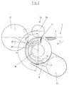
- FIG. 1 comprises a Cutting station 1 for window envelopes a knife roller 2 and a Counter tool serving stationary cutting bar 3, between which a sequence passed through envelope blanks 4 or an envelope sheet and is processed.
- the cutting bar 3 is clamped with a bar 6 in one Carrier 5 stored and together with this to the knife roller 2 and back this movable away.
- the cutting station 1 a has a rotating counter-roller 3 a Counter tool to the knife roller 2, between which a sequence of Envelope blanks 4 or an envelope sheet passed through and processed becomes.
- the counter roller 3a is mounted in a carrier, not shown, and is movable together with this to the knife roller 2 and away from it.
- An envelope blank 4 coming from a straight transport path is gripped by the knife roller 2 and passed along a circular path under the counter tool, cutting strip 3 or counter roller 3a, with a window opening 8 is cut out.
- the knife roller 2 (Fig. 4 and 5) on its circumference 9 has a plurality of arranged in rows 10 suction openings 11.
- the envelope blank 4 is held over a suction and transport angle range ⁇ by means of suction air on the knife roller 2 and then transferred to a roller 12.
- the piece of material 8 is held in the window knife periphery by means of suction air and, after a suction and transport angle range ⁇ , is discharged into a suction funnel 13.
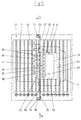
- Fig. 3 shows the knife roller 2, its storage and its essential parts on average, but without a foil knife and without those for fastening and Aligning a foil knife serving parts.
- the knife roller 2 comprises a carrier shaft 14 which is supported by means of ball bearings 15 in machine frames 16, 18 and can be driven by means of a gear wheel 17. Between the machine frames 16, 18, a cylindrical roller body part 19 is rotatably mounted on the carrier shaft 14, on the circumference 20 of which the suction openings 11 are arranged. In the roller body part 19 are at a distance d from the axis of rotation 2 the knife roller 2 suction channels 21 arranged axially parallel, which are in an air-conducting connection with the suction openings 11.
- a suction air control valve 31 is arranged on the end face of the roller body part 19 and is mounted on the frame wall 18 in a rotationally fixed manner by means of a spacing and centering bushing 32.
- the suction air control valve 31 has two separate, concentrically arranged suction air channels 39, 40, which are followed by fresh air channels 36, 37.
- the suction air channels 39, 40 are connected via a suction air supply 38 to a suction air source, not shown. From the suction air duct 39 or 40, the suction air ducts 21 can be acted upon by suction air over the suction and transport angle range ⁇ or ⁇ .
- a 3/3-way valve 41 in the roller body part 19 is assigned to each suction channel 21 towards the suction air control valve 31. With a 3/3-way valve, a suction channel 21 can be shut off or connected to the suction air control channel 39 or 40 via the through bore 42 or 43.
- the suction air control including the 3/3-way valves is the subject of the parallel German application 198 41 834.5 by the same applicant.
- the suction air channels 39 or. 40, a fresh air duct 36 or 37 is arranged downstream, from where the vacuum in the suction ducts 21 and the suction openings 11 is reduced.
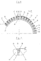
- a foil knife 24 has a thin base plate 61 made of magnetically permeable material with a thickness d 1 , as well as front and rear edges 62, 63 and side edges 64, 65. At least one one-piece sharp cutting edge 28 is arranged on the base plate 61 and forms a certain cutting shape.
- the cutting edge 28 for cutting out a window opening 8 is formed in an envelope blank 4, openings 75 are arranged which are in air-conducting connection with suction bores 11.
- slots 68 Seen in the direction of rotation 23 of the knife roller 2, in a region 67 adjoining the front edge 62, slots 68 are made in the base plate 61.
- the slots 68 are arranged in alignment and have a width b, a length d 5 and a distance d 6 from one another.
- the slots 68, the cutting edge 28 and also the front edge 62 have a predetermined fixed positional relationship to one another.
- At least one row 76 holding and positioning pins 66 are arranged, which protrude radially from the circumferential surface 20 with a height h which corresponds approximately to the thickness d 1 of the base plate 61.
- the holding and positioning pins 66 have a width b 1 and a distance d 2 from one another.
- the width b 1 is dimensioned so that it corresponds to the slot width b.
- a foil knife 24 For positionally precise positioning and fixing of a foil knife 24 on the roller body part 19, this is hung on the holding and positioning pins 66, so that the holding and positioning pins 66 protrude into the slots 68.
- the foil knife 24 is axially displaceable in the area of the slot length d 5 . Larger axial changes can be achieved by moving the foil knife 24 in the row 74 of the holding and positioning pins 66.
- the foil knife 24 is positively fixed in the circumferential direction by means of the holding and positioning pins 66 and non-positively fixed on the roller body part by means of the magnetic elements, so that the foil knife 24 does not move on the peripheral surface 20 even under difficult cutting conditions.
- 8-10 are some shape variants of the holding and positioning pins 66 shown.
- the holding and positioning pins 66 are integrally formed on a bar 27, which is arranged with a precise fit in an axially parallel channel 25 of the roller body part 19 and is fixed there by means of fastening elements 69.
- widening recesses 70 are formed, into which approximately radially aligned threads open, into which clamping screws 71 are screwed, which press with their heads 72 onto attachment surfaces 73 formed on the strips 27 at the ends and so define the bar 27 in the channel 25.
- the holding and positioning pins 66 have the same distances d 2 from one another, but different end distances d 3 and d 4 towards the attachment surfaces 73.
- d 4 is larger than d 3 by d 2/2 .
- the strip 27 in the channel 25 can be turned through 180 °.
- knife roller 2 are on the circumferential surface 20 distributed a plurality of channels 25, in which depending Requirement, depending on the number and size of the foil knife 2, strips 27 or only Filling pieces are arranged.
Landscapes
- Life Sciences & Earth Sciences (AREA)
- Forests & Forestry (AREA)
- Engineering & Computer Science (AREA)
- Mechanical Engineering (AREA)
- Perforating, Stamping-Out Or Severing By Means Other Than Cutting (AREA)
- Making Paper Articles (AREA)
- Nonmetal Cutting Devices (AREA)
- Control And Other Processes For Unpacking Of Materials (AREA)
- Fixing For Electrophotography (AREA)
- Details Of Cutting Devices (AREA)
- Processing And Handling Of Plastics And Other Materials For Molding In General (AREA)
- Registering, Tensioning, Guiding Webs, And Rollers Therefor (AREA)
Priority Applications (1)
| Application Number | Priority Date | Filing Date | Title |
|---|---|---|---|
| EP05026535A EP1655118B1 (fr) | 1999-06-04 | 2000-04-05 | Plaque de coupe aux filets pour un cylindre de coupe |
Applications Claiming Priority (2)
| Application Number | Priority Date | Filing Date | Title |
|---|---|---|---|
| DE19925612 | 1999-06-04 | ||
| DE19925612A DE19925612B4 (de) | 1999-06-04 | 1999-06-04 | Drehbare Messerwalze mit Folienmesser |
Related Child Applications (1)
| Application Number | Title | Priority Date | Filing Date |
|---|---|---|---|
| EP05026535A Division EP1655118B1 (fr) | 1999-06-04 | 2000-04-05 | Plaque de coupe aux filets pour un cylindre de coupe |
Publications (3)
| Publication Number | Publication Date |
|---|---|
| EP1057597A2 true EP1057597A2 (fr) | 2000-12-06 |
| EP1057597A3 EP1057597A3 (fr) | 2002-03-20 |
| EP1057597B1 EP1057597B1 (fr) | 2006-03-08 |
Family
ID=7910243
Family Applications (2)
| Application Number | Title | Priority Date | Filing Date |
|---|---|---|---|
| EP05026535A Expired - Lifetime EP1655118B1 (fr) | 1999-06-04 | 2000-04-05 | Plaque de coupe aux filets pour un cylindre de coupe |
| EP00107341A Expired - Lifetime EP1057597B1 (fr) | 1999-06-04 | 2000-04-05 | Dispositif de fixation d'une plaque de coupe aux filets sur un cylindre de coupe |
Family Applications Before (1)
| Application Number | Title | Priority Date | Filing Date |
|---|---|---|---|
| EP05026535A Expired - Lifetime EP1655118B1 (fr) | 1999-06-04 | 2000-04-05 | Plaque de coupe aux filets pour un cylindre de coupe |
Country Status (7)
| Country | Link |
|---|---|
| US (2) | US6494123B2 (fr) |
| EP (2) | EP1655118B1 (fr) |
| JP (1) | JP2001018191A (fr) |
| AT (2) | ATE319542T1 (fr) |
| CA (1) | CA2310523A1 (fr) |
| DE (4) | DE19925612B4 (fr) |
| ES (2) | ES2259951T3 (fr) |
Cited By (2)
| Publication number | Priority date | Publication date | Assignee | Title |
|---|---|---|---|---|
| DE102006014383A1 (de) * | 2006-03-29 | 2007-10-04 | WINKLER + DüNNEBIER AG | Folienmatrize zur Anordnung an einer rotierend antreibbaren Prägewalze, Verfahren zu deren Herstellung sowie Verwendung eines flächigen Rohmaterials zu deren Herstellung |
| DE102022111873A1 (de) | 2022-05-12 | 2023-11-16 | Matthews International GmbH | Anordnung zum Erzeugen einer Lagenhaftung von zumindest zwei Tissue-Lagen mittels Kaltverschweißen |
Families Citing this family (22)
| Publication number | Priority date | Publication date | Assignee | Title |
|---|---|---|---|---|
| DE10043517A1 (de) * | 2000-09-01 | 2002-03-14 | Winkler & Duennebier Ag | Verfahren und Vorrichtung zum formatabhängigen Einrichten von mindestens einem Werkzeug auf einem Werkzeugträger |
| DE10115595A1 (de) * | 2001-03-29 | 2002-10-02 | Winkler & Duennebier Ag | Messerwalze |
| US6715394B2 (en) * | 2002-05-07 | 2004-04-06 | W+D Machinery Co., Inc. | Rotatable die |
| US20040006633A1 (en) * | 2002-07-03 | 2004-01-08 | Intel Corporation | High-speed multi-processor, multi-thread queue implementation |
| US7455006B2 (en) * | 2002-11-05 | 2008-11-25 | Zsolt Toth | Modular/configurable die for a rotary die cutter |
| DE10354342A1 (de) | 2002-12-10 | 2004-06-24 | Heidelberger Druckmaschinen Ag | Einrichtung zur Bearbeitung eines Bedruckstoffes |
| DE10300234B3 (de) * | 2003-01-08 | 2004-07-15 | WINKLER + DüNNEBIER AG | Vorrichtung und Verfahren zur Nutzentrennung in einer Maschine zur Herstellung von aus einer Materialbahn ausgeschnittenen Flachmaterialstücken |
| DE102004058601A1 (de) | 2003-11-26 | 2005-08-04 | Schober Gmbh Werkzeug- Und Maschinenbau | Vorrichtung zur veredelnden Bearbeitung von bogenförmigen Substraten |
| JP4817939B2 (ja) * | 2006-04-03 | 2011-11-16 | 株式会社小森コーポレーション | プレート装着用シリンダ |
| DE102007003592B3 (de) * | 2007-01-24 | 2008-07-03 | WINKLER + DüNNEBIER AG | Saugwalze zum Transportieren von Flachmaterialzuschnitten |
| DE102007015300B4 (de) * | 2007-03-27 | 2013-07-04 | Winkler + Dünnebier Gmbh | Vorbruchwalze |
| US20080236349A1 (en) * | 2007-03-30 | 2008-10-02 | Weyerhaeuser Co. | Trim device for a lamination assembly |
| DE102008025490B4 (de) * | 2008-05-28 | 2017-01-05 | Winkler + Dünnebier Gmbh | Lagerung für eine beidseitig mit Saugluft beaufschlagbare Vakuumwalze |
| DE102008025899B4 (de) * | 2008-05-29 | 2010-11-11 | WINKLER+DüNNEBIER AG | Variable Fensterposition im Formatschnittfolienmesser |
| EP2186612A1 (fr) * | 2008-11-12 | 2010-05-19 | Gerhardt Ltd. | Découpe de plaque mince et cylindre pour maintenir magnétiquement la découpe |
| DE102009033575B4 (de) | 2009-07-16 | 2011-07-21 | Winkler+Dünnebier AG, 56564 | Folienmesser mit Saugkammer |
| CN106584595B (zh) * | 2016-12-22 | 2018-02-27 | 青岛盈科精密橡塑有限公司 | 一种润滑式圆刀模切治具 |
| EP3403782B1 (fr) * | 2017-05-16 | 2022-11-02 | Mayr-Melnhof Karton AG | Outil et procédé de fabrication d'un objet utile en feuille de carton |
| DE102017213389B4 (de) * | 2017-08-02 | 2022-07-28 | Heidelberger Druckmaschinen Ag | Rotationsstanze zum Ausstanzen eines Materialstücks aus einem Bedruckstoff |
| CN113305911A (zh) * | 2020-09-03 | 2021-08-27 | 汕头市佳宏纸制品有限公司 | 一种新型切棒机 |
| DE102022104070B4 (de) | 2022-02-22 | 2023-10-05 | Koenig & Bauer Ag | Vorrichtung und Verfahren zum Behandeln von Substraten |
| CN117123652B (zh) * | 2023-10-24 | 2024-03-19 | 奇精机械股份有限公司 | 一种洗衣机空气轴承的波纹状箔片的制造设备 |
Family Cites Families (29)
| Publication number | Priority date | Publication date | Assignee | Title |
|---|---|---|---|---|
| US3869985A (en) * | 1970-02-06 | 1975-03-11 | Rotographic Machinery Co | Clamping and tensioning a sheet on a cylinder |
| US3752042A (en) * | 1971-10-06 | 1973-08-14 | Castille Cutting Dies Inc | Adjustable die plate |
| US4116594A (en) * | 1975-12-12 | 1978-09-26 | Magna-Graphics Corporation | Embossing apparatus having magnetic roller and flexible embossing plates therefor |
| US4343215A (en) * | 1980-09-11 | 1982-08-10 | The United States Of America As Represented By The Secretary Of The Treasury | Perforating cylinder |
| DE3302038A1 (de) * | 1983-01-22 | 1984-07-26 | Winkler & Dünnebier, Maschinenfabrik und Eisengießerei GmbH & Co KG, 5450 Neuwied | Rotierende schneidvorrichtung zur herstellung von fensterausschnitten in briefhuellen und kartonagen |
| DE3417536A1 (de) * | 1984-05-11 | 1985-11-14 | Winkler & Dünnebier, Maschinenfabrik und Eisengießerei GmbH & Co KG, 5450 Neuwied | Verfahren und vorrichtung zum ausschneiden von fenstern in briefumschlaegen |
| US4878407A (en) * | 1986-05-01 | 1989-11-07 | The Ward Machinery Company | Vacuum die mount |
| CA1276871C (fr) * | 1986-11-03 | 1990-11-27 | Roland Falasconi | Fixation pour plaque d'outil a decouper les panneaux |
| FR2621519B1 (fr) * | 1987-10-12 | 1991-04-26 | Buland Jean | Dispositif rotatif de decoupe |
| DE4000078A1 (de) * | 1990-01-03 | 1991-07-04 | Winkler Duennebier Kg Masch | Messerwalze |
| US5088367A (en) * | 1990-07-30 | 1992-02-18 | Zerand-Bernal Group, Inc. | Rotary die with adjustable blade segment |
| DE4033850A1 (de) * | 1990-10-24 | 1992-04-30 | Minnesota Mining & Mfg | Zu einer rolle endlos aufgewickeltes, zusammengesetztes laminatklebeband und verfahren zur herstellung der rolle des laminatklebebandes |
| DE69404869T2 (de) * | 1993-01-22 | 1997-12-18 | Magnaflex Systems Ltd | Rotierende Stanzvorrichtung |
| NL9301289A (nl) * | 1993-07-22 | 1995-02-16 | Tno | Biologisch filter voor het verwijderen van vluchtige, hydrofobe verbindingen uit afgassen. |
| DE9316230U1 (de) * | 1993-10-23 | 1994-01-05 | Man Roland Druckmaschinen Ag, 63069 Offenbach | Vorrichtung zum passergerechten Positionieren eines Schneidbleches auf einem Schneidzylinder, vorzugsweise in Rotationsdruckmaschinen |
| US5570620A (en) * | 1993-12-22 | 1996-11-05 | Best Cutting Die Company | Panel cutting apparatus |
| DE4407287A1 (de) * | 1994-03-04 | 1995-09-07 | Baldwin Gegenheimer Gmbh | Auftragswerk |
| WO1995028261A1 (fr) | 1994-04-13 | 1995-10-26 | Winkler & Dünnebier | Emporte-piece souple et cylindre-support |
| US5697277A (en) | 1994-05-17 | 1997-12-16 | Best Cutting Die Company | Multi use rotary die plate system |
| JP2580493B2 (ja) * | 1994-08-09 | 1997-02-12 | 東亜機工株式会社 | サニタリー製品製造装置 |
| JPH08229885A (ja) * | 1995-02-27 | 1996-09-10 | Mitsubishi Heavy Ind Ltd | ロータリダイカッタのナイフシリンダ |
| US5524656A (en) * | 1995-03-10 | 1996-06-11 | Fluid Management Limited Partnership | Arrangement for cleaning dispense valves |
| US6026725A (en) * | 1995-04-10 | 2000-02-22 | Best Cutting Die Company | Panel cutting apparatus with waste repellant die structure |
| DE29603669U1 (de) * | 1996-02-29 | 1996-04-18 | Kocher + Beck Gmbh + Co. Rotationsstanztechnik Kg, 72124 Pliezhausen | Vorrichtung zum Beschneiden der Seitenränder von Papierzuschnitten |
| US6119570A (en) * | 1997-06-03 | 2000-09-19 | Best Cutting Die Company | Panel cutting apparatus with universal die holder |
| US6076444A (en) * | 1997-08-01 | 2000-06-20 | Best Cutting Die Company | Panel cutting apparatus with selectable matrices for vacuum and air |
| DE29805004U1 (de) * | 1998-03-19 | 1998-05-20 | Spilker Rotations- und Flachstanzenbau Gravieranstalt GmbH, 33818 Leopoldshöhe | Stanzzylinder |
| DE19841834A1 (de) * | 1998-09-12 | 2000-03-16 | Winkler & Duennebier Ag | Drehbare Messerwalze |
| US8199950B2 (en) | 2007-10-22 | 2012-06-12 | Sony Ericsson Mobile Communications Ab | Earphone and a method for providing an improved sound experience |
-
1999
- 1999-06-04 DE DE19925612A patent/DE19925612B4/de not_active Expired - Fee Related
- 1999-06-04 DE DE29921967U patent/DE29921967U1/de not_active Expired - Lifetime
-
2000
- 2000-04-05 DE DE50015825T patent/DE50015825D1/de not_active Expired - Lifetime
- 2000-04-05 ES ES00107341T patent/ES2259951T3/es not_active Expired - Lifetime
- 2000-04-05 ES ES05026535T patent/ES2339030T3/es not_active Expired - Lifetime
- 2000-04-05 AT AT00107341T patent/ATE319542T1/de not_active IP Right Cessation
- 2000-04-05 AT AT05026535T patent/ATE452009T1/de active
- 2000-04-05 DE DE50012334T patent/DE50012334D1/de not_active Expired - Lifetime
- 2000-04-05 EP EP05026535A patent/EP1655118B1/fr not_active Expired - Lifetime
- 2000-04-05 EP EP00107341A patent/EP1057597B1/fr not_active Expired - Lifetime
- 2000-05-05 US US09/565,511 patent/US6494123B2/en not_active Expired - Fee Related
- 2000-05-31 CA CA002310523A patent/CA2310523A1/fr not_active Abandoned
- 2000-06-01 JP JP2000164804A patent/JP2001018191A/ja active Pending
-
2002
- 2002-09-25 US US10/254,271 patent/US20030019343A1/en not_active Abandoned
Cited By (3)
| Publication number | Priority date | Publication date | Assignee | Title |
|---|---|---|---|---|
| DE102006014383A1 (de) * | 2006-03-29 | 2007-10-04 | WINKLER + DüNNEBIER AG | Folienmatrize zur Anordnung an einer rotierend antreibbaren Prägewalze, Verfahren zu deren Herstellung sowie Verwendung eines flächigen Rohmaterials zu deren Herstellung |
| DE102022111873A1 (de) | 2022-05-12 | 2023-11-16 | Matthews International GmbH | Anordnung zum Erzeugen einer Lagenhaftung von zumindest zwei Tissue-Lagen mittels Kaltverschweißen |
| WO2023217324A3 (fr) * | 2022-05-12 | 2024-03-07 | Matthews International GmbH | Dispositif pour produire une adhérence de couches d'au moins deux couches de tissu par soudage à froid |
Also Published As
| Publication number | Publication date |
|---|---|
| ATE319542T1 (de) | 2006-03-15 |
| US20030019343A1 (en) | 2003-01-30 |
| DE50015825D1 (de) | 2010-01-28 |
| ES2259951T3 (es) | 2006-11-01 |
| DE50012334D1 (de) | 2006-05-04 |
| CA2310523A1 (fr) | 2000-12-04 |
| EP1655118B1 (fr) | 2009-12-16 |
| ATE452009T1 (de) | 2010-01-15 |
| EP1057597B1 (fr) | 2006-03-08 |
| JP2001018191A (ja) | 2001-01-23 |
| EP1057597A3 (fr) | 2002-03-20 |
| DE19925612A1 (de) | 2000-12-07 |
| US20020092399A1 (en) | 2002-07-18 |
| DE29921967U1 (de) | 2000-03-23 |
| EP1655118A1 (fr) | 2006-05-10 |
| ES2339030T3 (es) | 2010-05-14 |
| DE19925612B4 (de) | 2007-10-31 |
| US6494123B2 (en) | 2002-12-17 |
Similar Documents
| Publication | Publication Date | Title |
|---|---|---|
| EP1057597A2 (fr) | Dispositif de fixation d'une plaque de coupe aux filets sur un cylindre de coupe | |
| EP0988943B1 (fr) | Cylindre pour la coupe rotative | |
| DE60114777T2 (de) | Vorrichtung zur übergabe von behältern mit einem führungsrad variabler geometrie | |
| EP0436142B1 (fr) | Rouleaux à couteaux | |
| DE69506697T2 (de) | Trägerzylinder für ein biegsames stanzwerkzeug | |
| DE2639218C2 (de) | Schneidwerkzeug für einen laufenden Streifen | |
| EP0367715B1 (fr) | Méthode et dispositif pour rogner des signatures | |
| DE19949412A1 (de) | Einrichtung zum Wenden von Bogen in einer Bogenrotationsdruckmaschine | |
| DE102008025899B4 (de) | Variable Fensterposition im Formatschnittfolienmesser | |
| DE69509871T2 (de) | Etikettiermaschine | |
| DE617605C (de) | Ausrichtevorrichtung | |
| DE102007030977A1 (de) | Schneidvorrichtung zum Schneiden eines Bandes unter Verwendung entgegengesetzt bzw. gegenüberliegend abgeschrägter Messer | |
| EP1777072B1 (fr) | Méthode de fabrication d'une plaque d'impression | |
| DE4243060A1 (de) | Einrichtung zum Beschneiden von flächigen Erzeugnissen, insbesondere mehrblättrigen Druckerzeugnissen | |
| EP0770571A2 (fr) | Dispositif pour le guidage transitoire de feuilles se succédant | |
| EP0253382B1 (fr) | Dispositif d'encollage pour étiqueteuses | |
| DE3805419A1 (de) | Einschnittvorrichtung fuer streifen von einwickelmaterial | |
| EP0903308B1 (fr) | Roue à étoile pour transférer des objets d'un premier convoyeur à un deuxième | |
| DE19711235A1 (de) | Vorrichtung für die Produktauslage mit einem Produktaufnahmebereich | |
| DE2624170B2 (de) | Seitenausrichtvorrichtung | |
| DE2738537B2 (de) | Drahteinzugapparat, insbesondere für eine Umformpresse | |
| DE29603669U1 (de) | Vorrichtung zum Beschneiden der Seitenränder von Papierzuschnitten | |
| DE2158082B2 (de) | Vorrichtung zum Querschneiden von Etiketten | |
| DE3131392A1 (de) | "vorrichtung zum winkelsynchronen drehen wenigstens zweier koerper, insbesondere fuer teile von druckmaschinen od.dgl." | |
| DE4244662C2 (de) | Verschließrollen-Einbau-/Ausbaumechanismus bei einer Dosenverschließmaschine |
Legal Events
| Date | Code | Title | Description |
|---|---|---|---|
| PUAI | Public reference made under article 153(3) epc to a published international application that has entered the european phase |
Free format text: ORIGINAL CODE: 0009012 |
|
| AK | Designated contracting states |
Kind code of ref document: A2 Designated state(s): AT BE CH CY DE DK ES FI FR GB GR IE IT LI LU MC NL PT SE |
|
| AX | Request for extension of the european patent |
Free format text: AL;LT;LV;MK;RO;SI |
|
| PUAL | Search report despatched |
Free format text: ORIGINAL CODE: 0009013 |
|
| AK | Designated contracting states |
Kind code of ref document: A3 Designated state(s): AT BE CH CY DE DK ES FI FR GB GR IE IT LI LU MC NL PT SE |
|
| AX | Request for extension of the european patent |
Free format text: AL;LT;LV;MK;RO;SI |
|
| 17P | Request for examination filed |
Effective date: 20020607 |
|
| AKX | Designation fees paid |
Free format text: AT BE CH CY DE DK ES FI FR GB GR IE IT LI LU MC NL PT SE |
|
| 17Q | First examination report despatched |
Effective date: 20031001 |
|
| GRAP | Despatch of communication of intention to grant a patent |
Free format text: ORIGINAL CODE: EPIDOSNIGR1 |
|
| GRAS | Grant fee paid |
Free format text: ORIGINAL CODE: EPIDOSNIGR3 |
|
| GRAC | Information related to communication of intention to grant a patent modified |
Free format text: ORIGINAL CODE: EPIDOSCIGR1 |
|
| GRAA | (expected) grant |
Free format text: ORIGINAL CODE: 0009210 |
|
| AK | Designated contracting states |
Kind code of ref document: B1 Designated state(s): AT BE CH CY DE DK ES FI FR GB GR IE IT LI LU MC NL PT SE |
|
| PG25 | Lapsed in a contracting state [announced via postgrant information from national office to epo] |
Ref country code: IE Free format text: LAPSE BECAUSE OF FAILURE TO SUBMIT A TRANSLATION OF THE DESCRIPTION OR TO PAY THE FEE WITHIN THE PRESCRIBED TIME-LIMIT Effective date: 20060308 Ref country code: IT Free format text: LAPSE BECAUSE OF FAILURE TO SUBMIT A TRANSLATION OF THE DESCRIPTION OR TO PAY THE FEE WITHIN THE PRESCRIBED TIME-LIMIT;WARNING: LAPSES OF ITALIAN PATENTS WITH EFFECTIVE DATE BEFORE 2007 MAY HAVE OCCURRED AT ANY TIME BEFORE 2007. THE CORRECT EFFECTIVE DATE MAY BE DIFFERENT FROM THE ONE RECORDED. Effective date: 20060308 Ref country code: FI Free format text: LAPSE BECAUSE OF FAILURE TO SUBMIT A TRANSLATION OF THE DESCRIPTION OR TO PAY THE FEE WITHIN THE PRESCRIBED TIME-LIMIT Effective date: 20060308 Ref country code: NL Free format text: LAPSE BECAUSE OF FAILURE TO SUBMIT A TRANSLATION OF THE DESCRIPTION OR TO PAY THE FEE WITHIN THE PRESCRIBED TIME-LIMIT Effective date: 20060308 |
|
| REG | Reference to a national code |
Ref country code: GB Ref legal event code: FG4D Free format text: NOT ENGLISH |
|
| REG | Reference to a national code |
Ref country code: CH Ref legal event code: EP |
|
| PG25 | Lapsed in a contracting state [announced via postgrant information from national office to epo] |
Ref country code: AT Free format text: LAPSE BECAUSE OF NON-PAYMENT OF DUE FEES Effective date: 20060405 |
|
| REG | Reference to a national code |
Ref country code: IE Ref legal event code: FG4D Free format text: LANGUAGE OF EP DOCUMENT: GERMAN |
|
| PG25 | Lapsed in a contracting state [announced via postgrant information from national office to epo] |
Ref country code: MC Free format text: LAPSE BECAUSE OF NON-PAYMENT OF DUE FEES Effective date: 20060430 Ref country code: CH Free format text: LAPSE BECAUSE OF NON-PAYMENT OF DUE FEES Effective date: 20060430 Ref country code: LI Free format text: LAPSE BECAUSE OF NON-PAYMENT OF DUE FEES Effective date: 20060430 |
|
| REF | Corresponds to: |
Ref document number: 50012334 Country of ref document: DE Date of ref document: 20060504 Kind code of ref document: P |
|
| PG25 | Lapsed in a contracting state [announced via postgrant information from national office to epo] |
Ref country code: DK Free format text: LAPSE BECAUSE OF FAILURE TO SUBMIT A TRANSLATION OF THE DESCRIPTION OR TO PAY THE FEE WITHIN THE PRESCRIBED TIME-LIMIT Effective date: 20060608 Ref country code: SE Free format text: LAPSE BECAUSE OF FAILURE TO SUBMIT A TRANSLATION OF THE DESCRIPTION OR TO PAY THE FEE WITHIN THE PRESCRIBED TIME-LIMIT Effective date: 20060608 |
|
| GBT | Gb: translation of ep patent filed (gb section 77(6)(a)/1977) |
Effective date: 20060619 |
|
| PG25 | Lapsed in a contracting state [announced via postgrant information from national office to epo] |
Ref country code: PT Free format text: LAPSE BECAUSE OF FAILURE TO SUBMIT A TRANSLATION OF THE DESCRIPTION OR TO PAY THE FEE WITHIN THE PRESCRIBED TIME-LIMIT Effective date: 20060808 |
|
| NLV1 | Nl: lapsed or annulled due to failure to fulfill the requirements of art. 29p and 29m of the patents act | ||
| REG | Reference to a national code |
Ref country code: ES Ref legal event code: FG2A Ref document number: 2259951 Country of ref document: ES Kind code of ref document: T3 |
|
| REG | Reference to a national code |
Ref country code: IE Ref legal event code: FD4D |
|
| PLBI | Opposition filed |
Free format text: ORIGINAL CODE: 0009260 |
|
| PLAZ | Examination of admissibility of opposition: despatch of communication + time limit |
Free format text: ORIGINAL CODE: EPIDOSNOPE2 |
|
| REG | Reference to a national code |
Ref country code: CH Ref legal event code: PL |
|
| 26 | Opposition filed |
Opponent name: KOCHER +BECK GMBH + CO. ROTATIONSSTANZTECHNIK KG Effective date: 20061128 |
|
| PLBA | Examination of admissibility of opposition: reply received |
Free format text: ORIGINAL CODE: EPIDOSNOPE4 |
|
| PLAX | Notice of opposition and request to file observation + time limit sent |
Free format text: ORIGINAL CODE: EPIDOSNOBS2 |
|
| EN | Fr: translation not filed | ||
| PLAF | Information modified related to communication of a notice of opposition and request to file observations + time limit |
Free format text: ORIGINAL CODE: EPIDOSCOBS2 |
|
| PLBB | Reply of patent proprietor to notice(s) of opposition received |
Free format text: ORIGINAL CODE: EPIDOSNOBS3 |
|
| PG25 | Lapsed in a contracting state [announced via postgrant information from national office to epo] |
Ref country code: GR Free format text: LAPSE BECAUSE OF FAILURE TO SUBMIT A TRANSLATION OF THE DESCRIPTION OR TO PAY THE FEE WITHIN THE PRESCRIBED TIME-LIMIT Effective date: 20060609 Ref country code: FR Free format text: LAPSE BECAUSE OF FAILURE TO SUBMIT A TRANSLATION OF THE DESCRIPTION OR TO PAY THE FEE WITHIN THE PRESCRIBED TIME-LIMIT Effective date: 20070309 |
|
| PG25 | Lapsed in a contracting state [announced via postgrant information from national office to epo] |
Ref country code: LU Free format text: LAPSE BECAUSE OF NON-PAYMENT OF DUE FEES Effective date: 20060405 |
|
| PG25 | Lapsed in a contracting state [announced via postgrant information from national office to epo] |
Ref country code: FR Free format text: LAPSE BECAUSE OF FAILURE TO SUBMIT A TRANSLATION OF THE DESCRIPTION OR TO PAY THE FEE WITHIN THE PRESCRIBED TIME-LIMIT Effective date: 20060430 |
|
| PG25 | Lapsed in a contracting state [announced via postgrant information from national office to epo] |
Ref country code: CY Free format text: LAPSE BECAUSE OF FAILURE TO SUBMIT A TRANSLATION OF THE DESCRIPTION OR TO PAY THE FEE WITHIN THE PRESCRIBED TIME-LIMIT Effective date: 20060308 Ref country code: FR Free format text: LAPSE BECAUSE OF FAILURE TO SUBMIT A TRANSLATION OF THE DESCRIPTION OR TO PAY THE FEE WITHIN THE PRESCRIBED TIME-LIMIT Effective date: 20060308 |
|
| PLCK | Communication despatched that opposition was rejected |
Free format text: ORIGINAL CODE: EPIDOSNREJ1 |
|
| PLBN | Opposition rejected |
Free format text: ORIGINAL CODE: 0009273 |
|
| STAA | Information on the status of an ep patent application or granted ep patent |
Free format text: STATUS: OPPOSITION REJECTED |
|
| 27O | Opposition rejected |
Effective date: 20080930 |
|
| PGFP | Annual fee paid to national office [announced via postgrant information from national office to epo] |
Ref country code: DE Payment date: 20110620 Year of fee payment: 12 |
|
| REG | Reference to a national code |
Ref country code: DE Ref legal event code: R081 Ref document number: 50012334 Country of ref document: DE Owner name: WINKLER + DUENNEBIER GMBH, DE Free format text: FORMER OWNER: WINKLER+DUENNEBIER AG, 56564 NEUWIED, DE Effective date: 20120327 |
|
| REG | Reference to a national code |
Ref country code: DE Ref legal event code: R119 Ref document number: 50012334 Country of ref document: DE Effective date: 20121101 |
|
| PGFP | Annual fee paid to national office [announced via postgrant information from national office to epo] |
Ref country code: ES Payment date: 20121023 Year of fee payment: 13 |
|
| PGFP | Annual fee paid to national office [announced via postgrant information from national office to epo] |
Ref country code: GB Payment date: 20130522 Year of fee payment: 14 |
|
| PGFP | Annual fee paid to national office [announced via postgrant information from national office to epo] |
Ref country code: BE Payment date: 20130521 Year of fee payment: 14 |
|
| PG25 | Lapsed in a contracting state [announced via postgrant information from national office to epo] |
Ref country code: DE Free format text: LAPSE BECAUSE OF NON-PAYMENT OF DUE FEES Effective date: 20121101 |
|
| GBPC | Gb: european patent ceased through non-payment of renewal fee |
Effective date: 20140405 |
|
| PG25 | Lapsed in a contracting state [announced via postgrant information from national office to epo] |
Ref country code: GB Free format text: LAPSE BECAUSE OF NON-PAYMENT OF DUE FEES Effective date: 20140405 |
|
| REG | Reference to a national code |
Ref country code: ES Ref legal event code: FD2A Effective date: 20150526 |
|
| PG25 | Lapsed in a contracting state [announced via postgrant information from national office to epo] |
Ref country code: ES Free format text: LAPSE BECAUSE OF NON-PAYMENT OF DUE FEES Effective date: 20140406 |
|
| PG25 | Lapsed in a contracting state [announced via postgrant information from national office to epo] |
Ref country code: BE Free format text: LAPSE BECAUSE OF NON-PAYMENT OF DUE FEES Effective date: 20140430 |