EP1057710B1 - Direction de véhicule - Google Patents
Direction de véhicule Download PDFInfo
- Publication number
- EP1057710B1 EP1057710B1 EP20000110918 EP00110918A EP1057710B1 EP 1057710 B1 EP1057710 B1 EP 1057710B1 EP 20000110918 EP20000110918 EP 20000110918 EP 00110918 A EP00110918 A EP 00110918A EP 1057710 B1 EP1057710 B1 EP 1057710B1
- Authority
- EP
- European Patent Office
- Prior art keywords
- steering
- column
- steering column
- motor vehicle
- driver
- Prior art date
- Legal status (The legal status is an assumption and is not a legal conclusion. Google has not performed a legal analysis and makes no representation as to the accuracy of the status listed.)
- Expired - Lifetime
Links
Images

Classifications
-
- B—PERFORMING OPERATIONS; TRANSPORTING
- B60—VEHICLES IN GENERAL
- B60R—VEHICLES, VEHICLE FITTINGS, OR VEHICLE PARTS, NOT OTHERWISE PROVIDED FOR
- B60R21/00—Arrangements or fittings on vehicles for protecting or preventing injuries to occupants or pedestrians in case of accidents or other traffic risks
- B60R21/02—Occupant safety arrangements or fittings, e.g. crash pads
- B60R21/16—Inflatable occupant restraints or confinements designed to inflate upon impact or impending impact, e.g. air bags
- B60R21/20—Arrangements for storing inflatable members in their non-use or deflated condition; Arrangement or mounting of air bag modules or components
- B60R21/203—Arrangements for storing inflatable members in their non-use or deflated condition; Arrangement or mounting of air bag modules or components in steering wheels or steering columns
-
- B—PERFORMING OPERATIONS; TRANSPORTING
- B62—LAND VEHICLES FOR TRAVELLING OTHERWISE THAN ON RAILS
- B62D—MOTOR VEHICLES; TRAILERS
- B62D1/00—Steering controls, i.e. means for initiating a change of direction of the vehicle
- B62D1/02—Steering controls, i.e. means for initiating a change of direction of the vehicle vehicle-mounted
- B62D1/16—Steering columns
- B62D1/18—Steering columns yieldable or adjustable, e.g. tiltable
- B62D1/184—Mechanisms for locking columns at selected positions
-
- B—PERFORMING OPERATIONS; TRANSPORTING
- B62—LAND VEHICLES FOR TRAVELLING OTHERWISE THAN ON RAILS
- B62D—MOTOR VEHICLES; TRAILERS
- B62D1/00—Steering controls, i.e. means for initiating a change of direction of the vehicle
- B62D1/02—Steering controls, i.e. means for initiating a change of direction of the vehicle vehicle-mounted
- B62D1/16—Steering columns
- B62D1/18—Steering columns yieldable or adjustable, e.g. tiltable
- B62D1/187—Steering columns yieldable or adjustable, e.g. tiltable with tilt adjustment; with tilt and axial adjustment
- B62D1/189—Steering columns yieldable or adjustable, e.g. tiltable with tilt adjustment; with tilt and axial adjustment the entire column being tiltable as a unit
-
- B—PERFORMING OPERATIONS; TRANSPORTING
- B62—LAND VEHICLES FOR TRAVELLING OTHERWISE THAN ON RAILS
- B62D—MOTOR VEHICLES; TRAILERS
- B62D1/00—Steering controls, i.e. means for initiating a change of direction of the vehicle
- B62D1/02—Steering controls, i.e. means for initiating a change of direction of the vehicle vehicle-mounted
- B62D1/16—Steering columns
- B62D1/18—Steering columns yieldable or adjustable, e.g. tiltable
- B62D1/19—Steering columns yieldable or adjustable, e.g. tiltable incorporating energy-absorbing arrangements, e.g. by being yieldable or collapsible
- B62D1/195—Yieldable supports for the steering column
Definitions
- the invention relates to a motor vehicle steering, in particular of a commercial vehicle steering, according to the preamble of claim 1.
- Such a motor vehicle steering system is known from WO 00/18632 and US 5 871 233 and contains a steering column which carries a steering wheel provided with an airbag.
- the steering column is supported on an end wall of the motor vehicle body and inclined relative to this at a certain angle.
- the steering column In commercial vehicles, the steering column is already employed relatively steep in the initial state, so that the angle of the driver's upper body relative to the steering wheel at impact is already unfavorable under the assumption of an unchanged by the frontal crash inclination of the steering column. In general, the steering column turns in a frontal crash but still further, so that there is the problem of a particularly low support of the chest area by the steering wheel airbag in commercial vehicles.
- a motor vehicle steering is known in which the steering column is pivotable about a pivot axis by means of a releasable by a collision sensor energy storage to compensate for the unwanted Aufstellne Trent the steering wheel.
- the energy storage device may be a cylinder piston drive, which is connected via a force-transmitting connection with the steering column and in the event of a collision by pressurizing the steering column pivots in the desired manner about the pivot axis.
- the amount of time required to pressurize the cylinder piston engine appears too long to ensure timely steering column pitch adjustment.
- pressure medium must constantly be stored in a container to supply the cylinder piston drive, whereby the risk of ineffectiveness of the tilt adjustment is due to the unavoidable leakage over time.
- the energy store includes a spring operatively connected to the steering column and biased, whereby in the event of a collision, a locking of the steering column released by detonation and thus the spring can exert a torque on the now freely pivoting steering column.
- the disadvantage here is that the spring is constantly under bias, which is why it wears off over time.
- the cylinder piston drive and the spring with the steering column are constantly in operative connection, whereby a driver-actuated steering column adjustment is hindered in collision-free operation.
- the present invention has for its object to provide a motor vehicle steering system of the type mentioned, by which, in the event of a collision, a pivoting of the steering column on the driver takes place at the high speed and is also reliably guaranteed over a longer period.
- the motor vehicle steering system according to the invention has the advantage that the desired steering column inclination adjustment is achieved very quickly by the abrupt and at the same time taking place with the triggering of the steering wheel airbag length shortening of Gurtschniquere Crushers.
- unfavorable angular positions of the steering wheel airbag can be corrected relative to the driver, even before it comes to the impact contact of the driver on the steering wheel airbag.
- the pivoting of the steering column generated by triggering the additional airbag on the driver is independent of the degree of deformation of the vehicle body, so that the unfavorable especially in commercial vehicles in collision initial condition angular position of the steering column is correctable even at low deformations of the vehicle body.
- the buckle retractor is pivoted at one end to the vehicle body and has at its other end a buckle, in which a belt tongue of a strap attached to the lower steering column part is locked.
- the lock on a pneumatically actuated pneumatic cylinder-piston unit through which in driver-actuated pressurization frictional engagement between the steering column and the steering column block can be canceled and thus a displacement and rotation of the steering column relative to the steering column block is possible.
- the pneumatic cylinder-piston unit can be acted upon at the same time with the release of the Gurtschniquere Consumers with pressure, so that the frictional engagement between the steering column and the steering column trestle suddenly dissolved and because of the loss of resistance, the steering column can be adjusted faster in the desired inclination.
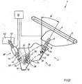
- the vehicle steering generally designated 1 in FIG. 1 is, according to the preferred embodiment, a commercial vehicle steering system.
- the commercial vehicle steering system 1 includes a steering wheel 4 arranged at the upper end of a steering column 2 with a steering wheel airbag 6 which is not unfolded according to the collision-free state of the commercial vehicle shown in FIG.
- the steering column 2 includes an upper steering column part 8 with a jacket tube 10, in which a steering wheel 4 connected to the steering shaft is rotatably received, which in turn is in communication with a steering gear, not shown.
- a steering column inclination ⁇ relative to the vertical which is relatively low in commercial vehicles and this results in an unfavorable impact angle of the driver on the steering wheel 4.
- the upper steering column part 8 is followed by a lower, opposite the upper steering column part 8 obtusely advanced steering column part, which is formed as a U-shaped, downwardly open displacement plate 12.
- the two legs 14 of the U-shaped sliding plate 12 are surrounded by two cheeks 16 of a steering column mounted on the vehicle body 18 and guided within the cheeks 16 by means of a slotted guide 20 and pivotally, with only one leg 14 because of the side view of FIG and a cheek 16 can be seen.
- the slotted guide 20 forms part of a driver-actuated adjusting mechanism 22 of the steering column 2, which also has a in Fig. 1 in the region of the slotted guide 20 by a dashed line shown pneumatic cylinder-piston unit 24 and a pivot axis 26.
- the pneumatic cylinder-piston unit 24 is received on the steering column block 18 parallel to the pivot axis 26 between the two legs 14 of the lower steering column part forming U-shaped sliding plate 12, wherein at the free ends of their piston and Cylinder jaws 28 are formed, which are also indicated in Fig. 1 by a respective dashed circular arc.
- the pneumatic cylinder-piston unit 24 is actuated by pressure and pressure relieved, wherein when pressurized by the then moving inwardly jaws 28, the legs 14 of the U-shaped sliding plate 12 to cancel a frictional engagement from the inside against the cheeks 16 of the steering column bracket 18 and Thus, a displacement and pivoting of the steering column 2 relative to the stationary steering column block 18 in the context of given by the slide guide 20 clearance is possible.
- the slotted guide 20 comprises on the one hand designed as straight cutouts in the cheeks 16 of the steering column bracket 18 and extending parallel to the upper steering column part 8 extending Verschiebekulissen 30 and on the other hand as circular arc cutouts in the legs 14 of the U-shaped sliding plate 12 and formed in the circumferential direction of an imaginary circular path around the Swivel axis 26 extending pivoting scenes 32, wherein the sliding scenes 30 and the pivoting scenes cover 32 on both sides crossing in pairs and by means of the jaws 28 of the pneumatic cylinder-piston unit 24 axially projecting outwardly stub axles 34 against each other.
- the pivot axis consists of a standing with the upper end of the U-shaped sliding plate 12 and extending transversely to this roller 26, the ends of which are guided in guide rails 36 in the cheeks 16 of the steering column 18 on both sides.
- the guide rails 36 are arranged parallel to the longitudinal extent of the Verschiebekulissen 30.
- the steering column 2 When pressure of the pneumatic cylinder-piston unit 24 thus the steering column 2 can be adjusted relative to the steering column block 18 along the Verschiebekulissen 30 axially and at the same time about the pivot axis 26 in its inclination, where it is held on the guide rails 36 of the steering column block 18 pivot axis 26 is supported and the pivoting movement is guided by the pivoting scenes 32.
- the set position of the steering column 2 is then fixed by the frictional engagement between the legs 14 of the lower steering column part 12 and the cheeks 16 of the steering column block 18 generated by the driver-actuated pressurization of the pneumatic cylinder-piston unit 24.
- An inventively designed as a pyrotechnic Gurtschêtre Mixor 38 control element for sudden adjustment of the inclination of the steering column 2 during a frontal collision is hinged at one end via a mounting lug 40 on the vehicle body 42 pivotally.
- a buckle 44 is fixed, in which a belt tongue 46 of a webbing 48 is locked.
- the webbing 48 is arranged at the lower end of the lower steering column part 12 and connects the two legs 14 with slight belt slack each other.
- 14 tabs are provided in the legs through which the ends of the webbing 48 are guided.
- the webbing 48 could also be permanently connected to the Gurtschnismre Consumor 38.
- the pneumatic cylinder-piston unit 24 is pressurized by the airbag control unit 50 at the same time with the release of the Gurtschêtre Consumers 38 and the steering wheel airbag 6, whereby the locking of the steering column 2 in the form of frictional engagement between it and the steering column block 18th is solved.
- an unobstructed pivotal movement of the steering column 2 is achieved from its original angular position by an angle d ⁇ in the direction of the driver.
- the impulse resulting from the sudden shortening of length of Gurtschniquere Cleanors 38 on the webbing 48 may be so large that the frictional engagement between the steering column 2 and the steering column block 18 can be overcome without loosening the clamp connection.
- the steering column 2 pivots clockwise through the length shortening of the belt buckle retractor 38 until the lower ends of the pivoting slots 32 formed in the legs 14 of the lower steering column part 12 abut the stub axles 34 of the stationary pneumatic cylinder piston unit Strike 24.
- the decisive for the size of the pivot angle d ⁇ parameters such.
Landscapes
- Engineering & Computer Science (AREA)
- Mechanical Engineering (AREA)
- Chemical & Material Sciences (AREA)
- Combustion & Propulsion (AREA)
- Transportation (AREA)
- Air Bags (AREA)
- Steering Controls (AREA)
Claims (9)
- Direction de véhicule automobile (1), notamment direction de véhicule industriel, comprenant une colonne de direction (2) portant un volant de direction (4) doté d'un airbag de volant (6), la colonne de direction (2) étant appuyée sur une structure du véhicule (18, 42) et étant pivotante, par rapport à celle-ci après qu'un dispositif de blocage (22) ait été surmonté ou débloqué au moyen d'un élément de réglage (38) activé en cas de collision, autour d'un axe de pivotement horizontal s'étendant essentiellement transversalement par rapport à l'axe longitudinal du véhicule, l'élément de réglage étant appuyé sur la structure du véhicule (18, 42) et pouvant être déclenché, en cas de collision frontale, en même temps que l'airbag de volant (6), et un couple pouvant être produit sur la colonne de direction (2) autour de l'axe de pivotement (26) par l'élément de réglage après l'activation de celui-ci, de telle manière que la colonne de direction (2) soit pivotante en direction du chauffeur, caractérisée en ce qu'un rétracteur pyrotechnique d'attache de ceinture (38) est prévu comme élément de réglage, qui est articulé de manière pivotante sur la structure du véhicule (42) avec l'une de ses extrémités et qui, sur son autre extrémité, présente une attache de ceinture (44), dans laquelle est encliquetée une languette de ceinture (46) d'une sangle de ceinture (48) fixée sur la partie inférieure de la colonne de direction (12), et le couple agissant sur la colonne de direction (2) en cas de collision frontale étant créé après le déclenchement de l'airbag de volant (6) par un raccourcissement de longueur ainsi déclenché par le rétracteur d'attache de ceinture (38).
- Direction de véhicule automobile selon la revendication 1, caractérisée en ce que la colonne de direction (2) s'appuie sur la structure du véhicule (18, 42) par l'intermédiaire de l'axe de pivotement (26) de manière similaire à un culbuteur, l'axe de pivotement (26) séparant essentiellement une partie supérieure (8) de la colonne de direction d'une partie inférieure (12) de la colonne de direction et le volant de direction (4) étant disposé sur l'extrémité supérieure de la partie supérieure (8) de la colonne de direction et le rétracteur d'attache de ceinture (38) étant en liaison active avec la partie inférieure (12) de la colonne de direction.
- Direction de véhicule automobile selon l'une des revendications 1 ou 2, caractérisée en ce que le dispositif de blocage comprend un mécanisme de réglage (22) pouvant être commandé par le chauffeur, destiné au réglage de l'inclinaison et au réglage axial de la colonne de direction (2), doté d'un guidage à coulisse (20), au moyen duquel les côtés (14) de la partie inférieure (12) de la colonne de direction, exécutée comme tôle coulissante en forme de U, sont guidés de manière coulissante et pivotante à l'intérieur de flasques (16) d'un support (18) de la colonne de direction fixé sur la structure du véhicule (42).
- Direction de véhicule automobile selon la revendication 3, caractérisée en ce que la sangle de ceinture (48) raccorde entre eux les côtés (14) de la tôle coulissante (12) en forme de U et présente un mou de sangle au moyen duquel un réglage commandé par le chauffeur de la colonne de direction (2) est rendu possible à l'état non déclenché du rétracteur d'attache de ceinture (38).
- Direction de véhicule automobile selon la revendication 3 ou 4, caractérisée en ce que le guidage à coulisse (20) comprend, d'une part, des coulisses de décalage (30) exécutées comme des sections droites dans les flasques (16) du support (18) de la colonne de direction et s'étendant parallèlement à la direction longitudinale de la colonne de direction et, d'autre part, des coulisses pivotantes (32) exécutées comme des sections d'arcs de cercle dans les côtés (14) de la tôle coulissante (12) en forme de U, les coulisses de décalage (30) et les coulisses pivotantes (32) se recouvrant des deux côtés par paires en se croisant et étant guidées les unes contre les autres par des axes (34) les traversant en les dépassant.
- Direction de véhicule automobile selon la revendication 5, caractérisée en ce que l'axe de pivotement est entouré par le mécanisme de réglage (22) commandable par le chauffeur et qu'il comprend un galet (26) lequel, étant en liaison avec l'extrémité supérieure de la tôle coulissante (12) en forme de U, s'étend transversalement par rapport à cette tôle coulissante et dont les extrémités sont guidées des deux côtés dans des rails de guidage (36) dans les flasques (16) du support (18) de la colonne de direction, lesquelles sont disposées parallèlement à l'étendue longitudinale des coulisses de décalage (30).
- Direction de véhicule automobile selon la revendication 6, caractérisée en ce que le mécanisme de réglage (22) commandable par le chauffeur présente une unité cylindre-piston, de préférence une unité cylindre pneumatique-piston (24) commandable par air comprimé, au moyen de laquelle, lors d'une montée en pression commandée par le chauffeur, une friction présente entre la colonne de direction (2) et le support (18) de la colonne de direction peut être supprimée, sur quoi un décalage et une rotation de la colonne de direction (2) sont rendus possibles par rapport au support (18) de la colonne de direction.
- Direction de véhicule automobile selon la revendication 7, caractérisée en ce que les côtés (14) de la tôle coulissante (12) en forme de U peuvent être tendus au moyen de l'unité cylindre pneumatique-piston (24) commandable par air comprimé afin de créer la friction depuis l'intérieur contre les flasques (16) du support (18) de la colonne de direction.
- Direction de véhicule automobile selon la revendication 8, caractérisée en ce que le rétracteur d'attache de ceinture (38) peut être déclenché par un signal d'un boîtier électronique d'airbag (50) qui pilote, en même que ce signal" un autre signal par lequel l'unité cylindre pneumatique-piston (24) peut être alimenté en air comprimé et, par ce moyen, une friction peut brusquement être déclenchée entre la colonne de direction (2) et le support (18) de la colonne de direction.
Applications Claiming Priority (2)
| Application Number | Priority Date | Filing Date | Title |
|---|---|---|---|
| DE1999125209 DE19925209A1 (de) | 1999-06-01 | 1999-06-01 | Kraftfahrzeuglenkung |
| DE19925209 | 1999-06-01 |
Publications (3)
| Publication Number | Publication Date |
|---|---|
| EP1057710A2 EP1057710A2 (fr) | 2000-12-06 |
| EP1057710A3 EP1057710A3 (fr) | 2003-01-15 |
| EP1057710B1 true EP1057710B1 (fr) | 2006-10-25 |
Family
ID=7909970
Family Applications (1)
| Application Number | Title | Priority Date | Filing Date |
|---|---|---|---|
| EP20000110918 Expired - Lifetime EP1057710B1 (fr) | 1999-06-01 | 2000-05-24 | Direction de véhicule |
Country Status (2)
| Country | Link |
|---|---|
| EP (1) | EP1057710B1 (fr) |
| DE (2) | DE19925209A1 (fr) |
Families Citing this family (6)
| Publication number | Priority date | Publication date | Assignee | Title |
|---|---|---|---|---|
| DE10121533C2 (de) * | 2001-05-03 | 2003-07-24 | Thyssen Krupp Automotive Ag | Sicherheitseinrichtung für Fahrzeuge |
| DE102005016789A1 (de) * | 2005-04-12 | 2006-10-19 | Zf Lenksysteme Gmbh | Anordnung einer Lenksäule |
| DE102005022408A1 (de) * | 2005-05-14 | 2006-11-16 | Zf Lenksysteme Gmbh | Anordnung einer Lenksäule |
| CN108749760B (zh) * | 2018-07-10 | 2023-08-22 | 肇庆学院 | 汽车方向盘脱离式防伤机构 |
| DE102019003711A1 (de) * | 2019-05-25 | 2020-11-26 | Man Truck & Bus Se | Vorrichtung zur Überwachung einer Lenkradstellung eines Kraftfahrzeugs |
| US11840274B2 (en) * | 2022-02-10 | 2023-12-12 | Honda Motor Co., Ltd. | Methods and systems for protecting a steering column from debris |
Family Cites Families (4)
| Publication number | Priority date | Publication date | Assignee | Title |
|---|---|---|---|---|
| DE3544345C2 (de) | 1984-12-24 | 1994-03-31 | Volkswagen Ag | Sicherheits-Lenksäule für Kraftfahrzeuge |
| JPH09142311A (ja) * | 1995-11-24 | 1997-06-03 | Tokai Rika Co Ltd | エアバッグを備えたステアリング装置 |
| DE19829239A1 (de) * | 1997-06-30 | 1999-01-07 | Volkswagen Ag | Lenkvorrichtung für ein Fahrzeug |
| DE19983199T1 (de) * | 1998-09-25 | 2002-02-28 | Douglas Autotech Corp | Lenkrad-Positionierungssystem für den Kollisionsfall |
-
1999
- 1999-06-01 DE DE1999125209 patent/DE19925209A1/de not_active Withdrawn
-
2000
- 2000-05-24 EP EP20000110918 patent/EP1057710B1/fr not_active Expired - Lifetime
- 2000-05-24 DE DE50013651T patent/DE50013651D1/de not_active Expired - Lifetime
Also Published As
| Publication number | Publication date |
|---|---|
| DE19925209A1 (de) | 2000-12-07 |
| DE50013651D1 (de) | 2006-12-07 |
| EP1057710A3 (fr) | 2003-01-15 |
| EP1057710A2 (fr) | 2000-12-06 |
Similar Documents
| Publication | Publication Date | Title |
|---|---|---|
| EP3268260B1 (fr) | Colonne de direction pour un véhicule automobile | |
| EP2698301B1 (fr) | Véhicule automobile avec volant abaissable | |
| EP0804352B1 (fr) | Systeme de securite pour automobile | |
| WO1985001707A1 (fr) | Installation d'utilisation de l'energie de collision d'un vehicule par un dispositif de securite destine a la protection des occupants du vehicule | |
| DE60110870T2 (de) | Stossenergie aufnehmende Lenksäule | |
| WO1985001709A1 (fr) | Dispositif de securite pour vehicule | |
| EP1027246B1 (fr) | Dispositif de protection pour le siege conducteur d'un vehicule automobile | |
| DE3888171T2 (de) | Lenksäulenanordnung für ein kraftfahrzeug. | |
| DE68916450T2 (de) | Lenkvorrichtungs-Tragkonstruktion eines Kraftfahrzeuges. | |
| DE3544345C2 (de) | Sicherheits-Lenksäule für Kraftfahrzeuge | |
| DE2131902A1 (de) | Lenkrad fuer ein Kraftfahrzeug od.dgl. | |
| DE69715998T2 (de) | Fahrzeug mit drehbarem Kotflügel | |
| EP1057710B1 (fr) | Direction de véhicule | |
| DE10294486B4 (de) | Aufprallaufnahme-Lenksäuleneinrichtung für Fahrzeuge | |
| EP0582107B1 (fr) | Colonne de direction d'un véhicule à moteur avec dispositif de rétractation pour la zone terminale du côté du volant | |
| EP1057712B1 (fr) | Direction de véhicule | |
| EP2001712A1 (fr) | Dispositif de protection des personnes dans des vehicules automobiles | |
| EP1266816B1 (fr) | Ensemble de verrouillage pour un ensemble de colonne de direction réglable en position | |
| DE19542491C1 (de) | Sicherheitslenksäule für Kraftfahrzeuge | |
| DE19546242C1 (de) | Schutzeinrichtung für die Insassen eines Kraftfahrzeuges | |
| DE102007021906A1 (de) | Lenksäulenfreigabemechanismus | |
| EP1057711B1 (fr) | Direction de véhicule | |
| DE4214790C2 (de) | Deaktivierbare Achslenkung | |
| DE19851390B4 (de) | Verfahren zur Festsetzung einer verstellbaren Kraftfahrzeuglenksäule und Vorrichtung zur Durchführung des Verfahrens | |
| DE4030841A1 (de) | Lenksaeule fuer kraftfahrzeuge |
Legal Events
| Date | Code | Title | Description |
|---|---|---|---|
| PUAI | Public reference made under article 153(3) epc to a published international application that has entered the european phase |
Free format text: ORIGINAL CODE: 0009012 |
|
| AK | Designated contracting states |
Kind code of ref document: A2 Designated state(s): AT BE CH CY DE DK ES FI FR GB GR IE IT LI LU MC NL PT SE |
|
| AX | Request for extension of the european patent |
Free format text: AL;LT;LV;MK;RO;SI |
|
| PUAL | Search report despatched |
Free format text: ORIGINAL CODE: 0009013 |
|
| AK | Designated contracting states |
Kind code of ref document: A3 Designated state(s): AT BE CH CY DE DK ES FI FR GB GR IE IT LI LU MC NL PT SE |
|
| AX | Request for extension of the european patent |
Free format text: AL;LT;LV;MK;RO;SI |
|
| RIC1 | Information provided on ipc code assigned before grant |
Free format text: 7B 62D 1/18 A, 7B 62D 1/19 B |
|
| 17P | Request for examination filed |
Effective date: 20030129 |
|
| AKX | Designation fees paid |
Designated state(s): DE FR IT NL SE |
|
| 17Q | First examination report despatched |
Effective date: 20050308 |
|
| GRAP | Despatch of communication of intention to grant a patent |
Free format text: ORIGINAL CODE: EPIDOSNIGR1 |
|
| GRAS | Grant fee paid |
Free format text: ORIGINAL CODE: EPIDOSNIGR3 |
|
| GRAA | (expected) grant |
Free format text: ORIGINAL CODE: 0009210 |
|
| AK | Designated contracting states |
Kind code of ref document: B1 Designated state(s): DE FR IT NL SE |
|
| PG25 | Lapsed in a contracting state [announced via postgrant information from national office to epo] |
Ref country code: IT Free format text: LAPSE BECAUSE OF FAILURE TO SUBMIT A TRANSLATION OF THE DESCRIPTION OR TO PAY THE FEE WITHIN THE PRESCRIBED TIME-LIMIT;WARNING: LAPSES OF ITALIAN PATENTS WITH EFFECTIVE DATE BEFORE 2007 MAY HAVE OCCURRED AT ANY TIME BEFORE 2007. THE CORRECT EFFECTIVE DATE MAY BE DIFFERENT FROM THE ONE RECORDED. Effective date: 20061025 |
|
| REF | Corresponds to: |
Ref document number: 50013651 Country of ref document: DE Date of ref document: 20061207 Kind code of ref document: P |
|
| REG | Reference to a national code |
Ref country code: SE Ref legal event code: TRGR |
|
| ET | Fr: translation filed | ||
| PLBE | No opposition filed within time limit |
Free format text: ORIGINAL CODE: 0009261 |
|
| STAA | Information on the status of an ep patent application or granted ep patent |
Free format text: STATUS: NO OPPOSITION FILED WITHIN TIME LIMIT |
|
| 26N | No opposition filed |
Effective date: 20070726 |
|
| REG | Reference to a national code |
Ref country code: NL Ref legal event code: TD Effective date: 20110420 |
|
| REG | Reference to a national code |
Ref country code: FR Ref legal event code: CD |
|
| REG | Reference to a national code |
Ref country code: DE Ref legal event code: R081 Ref document number: 50013651 Country of ref document: DE Owner name: MAN TRUCK & BUS AG, DE Free format text: FORMER OWNER: MAN NUTZFAHRZEUGE AG, 80995 MUENCHEN, DE Effective date: 20110518 |
|
| REG | Reference to a national code |
Ref country code: FR Ref legal event code: PLFP Year of fee payment: 17 |
|
| REG | Reference to a national code |
Ref country code: FR Ref legal event code: PLFP Year of fee payment: 18 |
|
| REG | Reference to a national code |
Ref country code: FR Ref legal event code: PLFP Year of fee payment: 19 |
|
| PGFP | Annual fee paid to national office [announced via postgrant information from national office to epo] |
Ref country code: NL Payment date: 20190527 Year of fee payment: 20 |
|
| PGFP | Annual fee paid to national office [announced via postgrant information from national office to epo] |
Ref country code: IT Payment date: 20190524 Year of fee payment: 20 |
|
| PGFP | Annual fee paid to national office [announced via postgrant information from national office to epo] |
Ref country code: SE Payment date: 20190527 Year of fee payment: 20 Ref country code: FR Payment date: 20190528 Year of fee payment: 20 |
|
| REG | Reference to a national code |
Ref country code: DE Ref legal event code: R081 Ref document number: 50013651 Country of ref document: DE Owner name: MAN TRUCK & BUS SE, DE Free format text: FORMER OWNER: MAN TRUCK & BUS AG, 80995 MUENCHEN, DE |
|
| PGFP | Annual fee paid to national office [announced via postgrant information from national office to epo] |
Ref country code: DE Payment date: 20190731 Year of fee payment: 20 |
|
| REG | Reference to a national code |
Ref country code: DE Ref legal event code: R071 Ref document number: 50013651 Country of ref document: DE |
|
| REG | Reference to a national code |
Ref country code: NL Ref legal event code: MK Effective date: 20200523 |
|
| REG | Reference to a national code |
Ref country code: SE Ref legal event code: EUG |