EP1057950A2 - Dispositif de liaison de deux éléments de construction - Google Patents
Dispositif de liaison de deux éléments de construction Download PDFInfo
- Publication number
- EP1057950A2 EP1057950A2 EP00112049A EP00112049A EP1057950A2 EP 1057950 A2 EP1057950 A2 EP 1057950A2 EP 00112049 A EP00112049 A EP 00112049A EP 00112049 A EP00112049 A EP 00112049A EP 1057950 A2 EP1057950 A2 EP 1057950A2
- Authority
- EP
- European Patent Office
- Prior art keywords
- load
- base
- bearing rod
- housing
- bore
- Prior art date
- Legal status (The legal status is an assumption and is not a legal conclusion. Google has not performed a legal analysis and makes no representation as to the accuracy of the status listed.)
- Granted
Links
Images

Classifications
-
- E—FIXED CONSTRUCTIONS
- E04—BUILDING
- E04B—GENERAL BUILDING CONSTRUCTIONS; WALLS, e.g. PARTITIONS; ROOFS; FLOORS; CEILINGS; INSULATION OR OTHER PROTECTION OF BUILDINGS
- E04B1/00—Constructions in general; Structures which are not restricted either to walls, e.g. partitions, or floors or ceilings or roofs
- E04B1/18—Structures comprising elongated load-supporting parts, e.g. columns, girders, skeletons
- E04B1/20—Structures comprising elongated load-supporting parts, e.g. columns, girders, skeletons the supporting parts consisting of concrete, e.g. reinforced concrete, or other stonelike material
- E04B1/21—Connections specially adapted therefor
- E04B1/215—Connections specially adapted therefor comprising metallic plates or parts
-
- E—FIXED CONSTRUCTIONS
- E04—BUILDING
- E04H—BUILDINGS OR LIKE STRUCTURES FOR PARTICULAR PURPOSES; SWIMMING OR SPLASH BATHS OR POOLS; MASTS; FENCING; TENTS OR CANOPIES, IN GENERAL
- E04H12/00—Towers; Masts or poles; Chimney stacks; Water-towers; Methods of erecting such structures
- E04H12/22—Sockets or holders for poles or posts
- E04H12/2253—Mounting poles or posts to the holder
- E04H12/2261—Mounting poles or posts to the holder on a flat base
Definitions
- the invention relates to a device for connecting two components, for example a post on a foundation, the device having a base with a bore, in which a holding means attacks and transmits forces and on the device or the base a or attack multiple load bars.
- European patent application 952 265 and this application underlying, priority-based German patent application 198 17 832 describe a column shoe for attachment of a concrete pile on a base.
- a bottom plate is provided with a bolt hole.
- a housing is provided which has several reinforcement bars records.
- the housing divides the base plate into several Sections.
- the housing has a housing base on which front reinforcing bars (here called anchoring links) are attached.
- rear reinforcement bars are provided, those in the at least two formed by the housing Sections are arranged.
- the German patent application 195 14 685 describes one Post shoe for attaching a concrete post to a base, the pile shoe being a bottom plate with a bolt hole and protruding vertically upwards on the base plate Has reinforcing bars. It is a rigid angle steel construction attached to the bottom plate, the side planes the angle steel structure is substantially perpendicular to the Level of the base plate are arranged.
- the angle steel construction is intended to absorb compensatory forces that are transverse to those of a bolt engaging in the bolt hole and the reinforcing bars absorbed forces act so that the compensating forces the required nominal load capacity of the reinforcing bars used do not increase.
- the present invention has set itself the task of a To improve the device, as described at the beginning, that the device is as easy to use and in use does not tend to come from the finished concrete part respectively the precast concrete, due to occurring Lateral forces to pull out.
- a device as described at the beginning where the component is not only on the load bearing rod supported on the device, but the Component itself on the device or on the base supported in such a way that no tilting of the base takes place under load.
- Such an embodiment is in the Manufacture of precast concrete parts can be easily implemented.
- the device described above is used, for example, as a mounting foot installed in precast concrete, the on the device or the base provided for the mounting foot comes into contact with the precast concrete. So it is possible the load transfer in the component not only via the load bearing bars to effect, but the component itself, in to use in the same way, the material or Deposits, such as reinforcing bars and the like of the component, in same way on the device or on the Base area supports.
- the dimensioning is done here in a conventional manner Way, such that no resulting rotation or Tipping moments remain, causing the base to tilt is excluded under load.
- the load bar for example as a reinforcement bar trained, resilient not only to pressure, but also to train is what else with a normal precast concrete or a concrete component is not possible.
- the task is also carried out by a device, as described at the outset, in which the load-bearing rod connected to the device by a screw connection is.
- the load curve can be used can be varied. The different forces lead to different diameters for the reinforcement bars.
- the device allows a quick exchange of the various load bars on the device, is it is possible to use the device with a small set of components modular for a variety of different needs build up. It is also possible that load lifting rods on the one hand under tension and on the other under pressure become. With appropriate planning, it is possible to develop the To capture device forces so that at the Device there are no resulting tilting moments.
- the Load suspension bars are also adjacent with different ones Force directions used. The load suspension describes not only a one-way force absorption, but if necessary one in both directions. This Variant therefore also solves the problem according to the invention.
- the mounting foot is used in the production of the first element, for example the support, built into this respectively concreted.
- the mounting foot a base with a hole through which a holding means, in particular a screw or a bolt, can be guided around the fastening foot with the second component, for example to connect the foundation foot.
- the mounting foot acts with appropriate screw sleeves and the like together, which are provided in the second element.
- the mounting foot or the device is designed as an easily manufactured component is and at the same time is suitable, the holding forces that over the fastening screw or fastening bolt the base area are embossed to transfer it safely into the element. It should also be noted that the mounting foot not only easy to manufacture, but also simple on the element usually designed as a precast concrete element can be attached or installed. This is achieved in particular through the design of the base area as a flex-resistant Element that is capable of absorbing the holding forces.
- the reinforcement bars end on the device Trained load bars in the first component are concreted. It is intended that possibly only one but also several reinforcement bars on the mounting foot are connected.
- the reinforcing bars are in the precast concrete concreted and transmit the tensile forces in the Element. Since the holding forces on the mounting foot additional element to be transferred, it is convenient to use the rebar to be attached to the mounting foot to the Forces favorably directly from the reinforcing bar of the first component, for example in the reinforcement or in the Transfer anchor of the second component. The order is taken as far as possible so that if possible no offset forces arise perpendicular to the orientation of the reinforcing bars, who would try, for example, the mounting foot to rotate or tilt relative to the element.
- the reinforcing bars on the mounting base welded or screwed into a screw sleeve are attached.
- a screw sleeve is provided, the interacts with the rebar.
- the screw sleeve is for Example on the device or the base welded on.
- the end of the reinforcing bar shows external thread corresponding to the internal thread of the screw sleeve on and thus allows a very simple assembly of the mounting foot. It is possible through such a configuration
- the mounting foot has a modular structure. Corresponding the desired length of the load suspension rods reinforcement bars of different lengths screwed into the sleeves. This assembly can be done when creating the precast concrete part be used. Depending on the required reinforcement it is possible to put one or more reinforcing bars in each provided screw sleeves. By such Design, the device is optimal to the respective needs customizable.
- the reinforcing bar on the mounting foot is welded on.
- the device is one of has several side surfaces existing housing.
- the load bearing bar / reinforcement bar is, for example, a fillet weld in a mechanically resilient manner with this side surface connected.
- the mounting foot on one or more side surfaces formed housing carries and the side surface is substantially perpendicular to the base surface and the housing is the base in a connection area divided with the bore and a connection area. That now proposed housing may take over several Functions simultaneously.
- Housing is relatively thin-walled. As a rule, the Fastening base concreted in a first precast concrete part. In this case, the housing acts as a lost formwork element and then leaves the hole through which the retaining bolt or to insert the retaining screw or another retaining means is free of the incoming concrete. It is sufficient if the side surfaces are relatively thin-walled, because in these otherwise attack no holding forces and so on.
- the rebar in Connection area attached to the housing and / or the base is welded in particular.
- the Reinforcement bar attached to the housing i.e. the side surface is the holding forces from the reinforcement bar over the Housing or the side surface on the base and then transferred to the other element via the retaining bolt.
- the side surface, i.e. the housing becomes mechanical strains and not only forms a formwork against shrinkage of concrete in the hole.
- the side surface is mechanically more stable if necessary is designed as an angularly rigid sheet or piece of metal.
- the side surface or the housing is favorably welded on the base, which on the one hand simple manufacture and secondly a mechanical one there is a strong connection.
- connection area with the Hole is relatively narrow and just as much Surface has that the holding means, for example the screw Can be fastened in the hole or with a tool is tightenable.
- the holding means for example the screw Can be fastened in the hole or with a tool is tightenable.
- these are proportional Mounted close to the housing in order to create a straight line Force transmission from the reinforcing bars into the retaining bolts or to reach the holding means.
- the housing has a cover plate or surface has, which rests on the side surface. This creates a connection area on several sides before entering protected from concrete when manufacturing the precast concrete part is.
- a reinforcement bar on the cover plate for example screwed into a screw sleeve or welded
- That in the device (with or without housing) Body is set, which covers the hole.
- the Body that is designed, for example, as a styrofoam body, serves as a formwork element and avoids that the still liquid Concrete in particular runs in the hole in the base and seals them and makes them unusable. After making the body is simply removed from the element, whereby the Cavity arises in the area of the connection area and the Bore releases.
- the invention also relates to a column foot consisting of two or several mounting feet, as described above.
- the mounting foot in particular this support foot in the corner or angle area of the element or the support is arranged.
- the individual mounting feet with each other to Example connected by a common plate or struts are or the reinforcement bars are arranged one below the other are that a mounting foot is arranged at their respective ends and so give the column foot as described.
- the invention also relates to a building, in particular a hall with trusses resting on supports, the Columns are supported by foundations and in particular the components prop, truss and / or foundation as a concrete part or precast concrete are formed, and with the help the aforementioned column foot or the device, if necessary also angularly rigid, are interconnected.
- the stake The invention is not only related to the vertical connection limited superimposed components, but can in the same way also on the connection of angularly abutting Components, such as laying on a tie on a support.
- the device connects horizontally oriented or otherwise angled Realize components.
- a great advantage of the invention is that this is also in an angularly rigid relationship can be fixed to each other and so for example a stiffening Scaffold.
- the device according to the invention not only on the area of use of concrete components it as concrete elements or precast concrete parts made from in-situ concrete, is limited, but that the device in same way for connecting components from others Materials such as wood, steel and so on can be used.
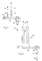
- 2 is the configuration according to the state of the Technology, especially according to the German published patent application 195 14 685.
- the basic structure of the device results from a base plate 53 which has a bore 48 has, in which a holding means 4 can be inserted.
- the load bearing bars / reinforcing bars 32 are opened Train upwards, according to arrow 30, loaded.
- the holding device 4 the fastening force and, if necessary, the Weight down, according to arrow 40 '. derived.
- the direction of the Surface pressure of the surface force 33 may also be parallel to the clamping direction 40 of the holding means 4. It follows from 1 that the use a side surface 51, which for compensation or Absorption of the transverse forces 34, 35 is necessary in the 1 can be completely dispensed with. The Side surface can actually function as a lost formwork part can be reduced.
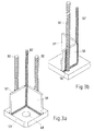
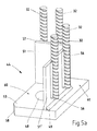
- Fig. 3a shows a front view
- Fig. 3b shows a rear view
- 3a, 3b are at right angles to the embodiment according to FIG. 1 to the base upward side faces 51, 51 'on.
- the side surfaces 51, 51 ' are also mutually arranged approximately at right angles and each formed in one piece. They therefore do not form an angularly rigid construction.
- the reinforcing bar 32' is arranged in the connection area between the two side surfaces 51, 51 '.
- the reinforcing bar 32' is arranged.
- Corresponding the load on it is thinner designed as the load bearing rods carrying a larger load 32 with respect to the respective side surfaces 51, 51 ' are arranged centrally upwards.
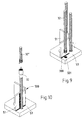
- Fig. 7 it is indicated that between the two side walls 51, 51 'there is a gap 500.
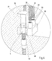
- Fig. 8 shows a side surface 51 as part of the housing 57, which is one-piece, L-shaped angled.
- a screw 502 is inserted into the back of this hole performed with screw head, such that the threaded part the plane of the base 53 protrudes upwards.
- the rebar 32 has a sleeve 301 at one end Internal thread that cooperates with the thread of screw 502. This makes it possible, in a simple manner, accordingly the calculated or constructively specified Loads different load bearing bars 32, 32 ' to be attached to the same base 53.
- a bolt 503 with external thread is provided, which engages in the screw sleeve 301.
- the bolt 503 is welded into the base, for example.
- a reverse principle is proposed, at an external thread 300 at a free end of the reinforcing bar 32 is provided, which in a bore with an internal thread 501 in the base 53 can be screwed in.
- the gap 500 is dimensioned so that the inflow of Concrete, according to the toughness of the concrete, is omitted. If necessary, one cannot go further into the gap 500 Shown sealing body, for example made of polystyrene, inserted become.
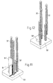
- a reinforcing bar 32 by a fillet weld 56 on the side surface 51 attached.
- the reinforcing bar 32 carries at its upper end a sleeve with an internal thread, into which another reinforcement bar 32 '', can be screwed in with an external thread.
- Fig. 11 is particularly indicated that the housing 57 here of three, angled with respect to each other oriented side parts 51, 51 ', 51' 'is formed.
- a reinforcing bar 32 welded on each of the individual side parts 51, 51 ', 51' 'there is a reinforcing bar 32 welded.
- the calculated load a small number of To provide reinforcing bars 32 here.
- a Housing or of side walls that such Form housing, can be dispensed with, as for example in Fig. 12 is indicated.
- further Reinforcing bars are similar to those in Fig. 8 further reinforcement bar on the arranged in the base plate 53 Welded load suspension rod.
- a body for covering the hole 48, a body, not shown, is provided.
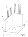
- 5 a, 5 b are two versions of an embodiment of the Fastening foot according to the invention shown.
- the mounting foot for example, with additional mounting feet combined together to form a column base.
- the mounting foot 44 in the corner area of a Element, for example the column of a precast column.
- the fastening foot 44 consists of a base 53, which is essentially flat, square, has rectangular or round cross section and a Has thickness, which is designed so that the base as such is resistant to bending. It is usually made of metal, for Example made of iron or steel or structural steel.
- a base 53 which is essentially flat, square, has rectangular or round cross section and a Has thickness, which is designed so that the base as such is resistant to bending. It is usually made of metal, for Example made of iron or steel or structural steel.
- side surfaces 51 are provided which have a housing 57 form.
- To connect the housing 57 to the base 53 is one Weld 49 provided.
- connection area 60 This is in the one shown here Example arranged in the connection area 61, but it can also on the other side of the side surface 51, in the connection area 60 may be arranged. However, it is cheaper to use the connection area 60 relatively narrow and thereby bring the reinforcement bars as close as possible to the hole, which then results in a weld seam 49 in the inner region, ie in the connection region 60 would bother.
- connection area 60 is on the edge of the precast concrete and so one best possible accessibility of the bore 48 for screwing in / Fastening a holding means 4 (screw, screw bolt, Bolts for welding and so on) allowed.
- reinforcement bars 32 there are several in particular four reinforcement bars 32 indicated, which face each other the base 53 substantially at right angles extend above.
- the reinforcing bars 32 are in the connection area 61 by weld seams 56 on the side surfaces 51, 51 ' welded on.
- the reinforcement bars 32 are here connected in the connection area 61, which makes it possible to form the connection area 60 relatively narrow.
- reinforcement bars 32 Example to arrange in the connection area then of course the screwing in of the screw or the holding means 4 in the bore 48 may be difficult.
- the relative simple construction of the housing 57, as shown here, two side surfaces 51, allows a practical division in the connection area and in the connection area, with the chosen arrangement the reinforcing bars 32 so be brought close to the axis of the bore 48 that on additional means to accommodate any that may occur Lateral forces (which due to the offset of the direction of force in the reinforcing bars 32 in relation to the arrangement of the holding means 4 exist in the bore 48) can be omitted. This results in a very simple design of the mounting foot 44.
- a further development of the invention also provides the reinforcing bars 32 on the side surface 51 and to arrange the housing 57 so that the by several reinforcing bars 32 resulting force that is transmitted, if possible aligned with the axis of the bore 48, creating a possible Pushing or tilting force is avoided.
- 5 a shows that the housing 57 consists of two mutually perpendicular Side surfaces 51, is cube-shaped.
- 3 c is alternatively a section of a lateral surface is shown, through which the reinforcing bars 32 are even closer to the bore 48 can be positioned.
- Screw sleeves 55 are provided, for example on the Base 53 is placed on, for example welded, the lower ends of the reinforcing bars 32 being threaded 33 are fitted in the internal thread of the screw sleeves 55 intervene. Not only one is used here as a screw sleeve viewed on the base 53 sleeve, it is also possible a thread cut into the base 53 as To look at screw sleeve, then the base area 53 has a sufficient thickness.
- the volume of the housing 57 in the connection area 60 is included, if necessary also with one further illustrated body when concreting the Fastening foot in the precast concrete to be covered to ensure the free accessibility of the bore 48.
Landscapes
- Engineering & Computer Science (AREA)
- Architecture (AREA)
- Civil Engineering (AREA)
- Structural Engineering (AREA)
- Physics & Mathematics (AREA)
- Electromagnetism (AREA)
- Joining Of Building Structures In Genera (AREA)
- Coupling Device And Connection With Printed Circuit (AREA)
- Electrical Discharge Machining, Electrochemical Machining, And Combined Machining (AREA)
- Gyroscopes (AREA)
- Earth Drilling (AREA)
- Reinforcement Elements For Buildings (AREA)
- Internal Circuitry In Semiconductor Integrated Circuit Devices (AREA)
Applications Claiming Priority (4)
| Application Number | Priority Date | Filing Date | Title |
|---|---|---|---|
| DE29909731 | 1999-06-04 | ||
| DE29909731U | 1999-06-04 | ||
| DE20002501U | 2000-02-14 | ||
| DE20002501U DE20002501U1 (de) | 1999-06-04 | 2000-02-14 | Fertigteilstütze |
Publications (3)
| Publication Number | Publication Date |
|---|---|
| EP1057950A2 true EP1057950A2 (fr) | 2000-12-06 |
| EP1057950A3 EP1057950A3 (fr) | 2001-10-17 |
| EP1057950B1 EP1057950B1 (fr) | 2008-08-06 |
Family
ID=26056075
Family Applications (1)
| Application Number | Title | Priority Date | Filing Date |
|---|---|---|---|
| EP00112049A Expired - Lifetime EP1057950B1 (fr) | 1999-06-04 | 2000-06-02 | Dispositif de liaison de deux éléments de construction |
Country Status (5)
| Country | Link |
|---|---|
| EP (1) | EP1057950B1 (fr) |
| AT (1) | ATE403789T1 (fr) |
| DE (3) | DE20002501U1 (fr) |
| DK (1) | DK1057950T3 (fr) |
| ES (1) | ES2311445T3 (fr) |
Cited By (9)
| Publication number | Priority date | Publication date | Assignee | Title |
|---|---|---|---|---|
| EP1531213A1 (fr) * | 2003-11-13 | 2005-05-18 | HALFEN GmbH & CO. Kommanditgesellschaft | Sabot de pieu pour pieu en béton |
| EP2381045A1 (fr) * | 2010-04-26 | 2011-10-26 | Ruredil S.p.A. | Connexion mécanique pour produits préfabriqués en béton armé et procédé de production correspondant |
| EP2685019A1 (fr) * | 2012-07-13 | 2014-01-15 | Gerhard Krummel | Elément de liaison entre deux composants en béton |
| WO2014096523A1 (fr) | 2012-12-18 | 2014-06-26 | Peikko Group Oy | Pied de colonne |
| NL1040406C2 (nl) * | 2013-09-24 | 2015-04-07 | Mattheus Hendrikus Wieringen | Een innovatief vernieuwend woon- en bouwconcept "de groeiwoning". een demontabel duurzaam prefab beton gebouwcasco; flexibel samengesteld uit wooneenheden die in grootte variabel zijn en met vrije architectuur voor de gebouwschil. |
| EP2935711A4 (fr) * | 2012-12-18 | 2016-08-10 | Peikko Group Oy | Sabot de colonne |
| WO2021009409A1 (fr) * | 2019-07-12 | 2021-01-21 | Peikko Group Oy | Sabot de colonne permettant de fixer des colonnes en béton armé à une base |
| CN114232791A (zh) * | 2021-12-30 | 2022-03-25 | 甘肃安居建设工程集团有限公司 | 装配式建筑施工荷载自承重体系及其施工方法 |
| PL132438U1 (pl) * | 2024-10-29 | 2025-03-17 | Politechnika Częstochowska | Łącznik kotwiący |
Families Citing this family (9)
| Publication number | Priority date | Publication date | Assignee | Title |
|---|---|---|---|---|
| FI20020422A7 (fi) * | 2002-03-05 | 2003-09-06 | Tartuntamarkkinointi Oy | Pilarikenkä |
| DE10312701B4 (de) * | 2003-03-21 | 2007-10-31 | Krummel, Gerhard, Dipl.-Ing. | Anordnung zur Fixierung eines Ankerbolzens einer Stütze in einem Fundament |
| DE102006023296A1 (de) * | 2006-05-18 | 2007-11-22 | Krummel, Gerhard, Dipl.-Ing. | Vorrichtung zur Befestigung einer Betonstütze auf einem Fundament, insbesondere einem Betonfundament |
| DE102018116542A1 (de) | 2018-07-09 | 2020-01-09 | Georg Weidner | Verbindungssystem mit Ankerschloss |
| ES2784948B2 (es) * | 2019-03-26 | 2021-11-24 | Zambelli Sergio | Anclaje para soporte de hormigon prefabricado. |
| IT201900014997A1 (it) * | 2019-08-23 | 2021-02-23 | Julio Cesar Bassorelli | Kit di fissaggio, in particolare di pilastri, e relativo metodo di fissaggio |
| NO346092B1 (no) * | 2020-08-27 | 2022-02-07 | Comrod As | Feste for en komposittmast til en oppover-ragende konisk formet festesøyle med en ringformet flens, og fremgangamåte for å feste en komposittmast med en slik konisk formet festesøyle til grunnen |
| CN119032213A (zh) | 2022-03-15 | 2024-11-26 | 力维拓有限责任公司 | 预制靴底座和预制靴 |
| PL448686A1 (pl) * | 2024-05-27 | 2025-12-01 | Pfeifer Polska Spółka Z Ograniczoną Odpowiedzialnością | Łącznik do mocowania żelbetowych słupów, belek lub ścian oraz układ montażowy do mocowania żelbetowych słupów, belek lub ścian |
Family Cites Families (10)
| Publication number | Priority date | Publication date | Assignee | Title |
|---|---|---|---|---|
| DE2236377A1 (de) * | 1972-07-25 | 1974-02-07 | Emil Gubler | Verfahren zur herstellung einer bodenverankerung, insbesondere fuer baukonstruktionen, pfeiler, masten und pfosten, und gemaess dem verfahren hergestellte bodenverankerung |
| DE2236503C3 (de) * | 1972-07-25 | 1975-06-26 | Dyckerhoff & Widmann Ag, 8000 Muenchen | Preßmuffenverbindung für gerippte Bewehrungsstäbe |
| DE2806494A1 (de) * | 1978-02-16 | 1979-08-23 | Karl Dr Ing Johannsen | Koecherfundament fuer hochbaustuetzen |
| SE455004B (sv) * | 1986-12-19 | 1988-06-13 | Wikells Byggberekningar Ab | Sett att festa en pelare pa ett fundament |
| CH676270A5 (en) * | 1988-09-02 | 1990-12-28 | Walser & Co Ag | Component-securing equipment to concrete - has stirrup with tapped, ends screwed to baseplate fixed to shuttering |
| DE4037438C2 (de) * | 1990-11-24 | 1996-01-18 | Bremer Gmbh | Transportables Stahlbetonfundament für eine Stütze |
| FI941936L (fi) * | 1994-04-26 | 1995-10-27 | Teraespeikko Oy | Pilarikenkä |
| EP0784127A1 (fr) * | 1996-01-10 | 1997-07-16 | Bam Ag | Elément d'ancrage pour ouvrages en béton armé |
| AU722320B2 (en) * | 1996-07-16 | 2000-07-27 | R. O'rourke And Son Limited | Improvements in or relating to concrete structures |
| DE19817832A1 (de) * | 1998-04-22 | 1999-10-28 | Peikko Gmbh | Stützenschuh zur Befestigung eines Betonpfahles auf einer Unterlage |
-
2000
- 2000-02-14 DE DE20002501U patent/DE20002501U1/de not_active Expired - Lifetime
- 2000-06-02 DK DK00112049T patent/DK1057950T3/da active
- 2000-06-02 DE DE10027037A patent/DE10027037B4/de not_active Expired - Lifetime
- 2000-06-02 DE DE50015295T patent/DE50015295D1/de not_active Expired - Lifetime
- 2000-06-02 ES ES00112049T patent/ES2311445T3/es not_active Expired - Lifetime
- 2000-06-02 AT AT00112049T patent/ATE403789T1/de active
- 2000-06-02 EP EP00112049A patent/EP1057950B1/fr not_active Expired - Lifetime
Cited By (17)
| Publication number | Priority date | Publication date | Assignee | Title |
|---|---|---|---|---|
| EP1531213A1 (fr) * | 2003-11-13 | 2005-05-18 | HALFEN GmbH & CO. Kommanditgesellschaft | Sabot de pieu pour pieu en béton |
| US7726091B2 (en) | 2003-11-13 | 2010-06-01 | Halfen Gmbh & Co. Kg | Support shoe for concrete pylons |
| EP2381045A1 (fr) * | 2010-04-26 | 2011-10-26 | Ruredil S.p.A. | Connexion mécanique pour produits préfabriqués en béton armé et procédé de production correspondant |
| ITMI20100711A1 (it) * | 2010-04-26 | 2011-10-27 | Ruredil Spa | "collegamento meccanico per manufatti prefabbricati in conglomerato cementizio armato e procedimento per produrli" |
| EP2685019A1 (fr) * | 2012-07-13 | 2014-01-15 | Gerhard Krummel | Elément de liaison entre deux composants en béton |
| EP2935711A4 (fr) * | 2012-12-18 | 2016-08-10 | Peikko Group Oy | Sabot de colonne |
| EP2935712A4 (fr) * | 2012-12-18 | 2016-08-03 | Peikko Group Oy | Pied de colonne |
| WO2014096523A1 (fr) | 2012-12-18 | 2014-06-26 | Peikko Group Oy | Pied de colonne |
| US9512610B2 (en) | 2012-12-18 | 2016-12-06 | Peikko Group Oy | Column shoe |
| NL1040406C2 (nl) * | 2013-09-24 | 2015-04-07 | Mattheus Hendrikus Wieringen | Een innovatief vernieuwend woon- en bouwconcept "de groeiwoning". een demontabel duurzaam prefab beton gebouwcasco; flexibel samengesteld uit wooneenheden die in grootte variabel zijn en met vrije architectuur voor de gebouwschil. |
| WO2021009409A1 (fr) * | 2019-07-12 | 2021-01-21 | Peikko Group Oy | Sabot de colonne permettant de fixer des colonnes en béton armé à une base |
| CN114127366A (zh) * | 2019-07-12 | 2022-03-01 | 佩克集团有限公司 | 用于将加强混凝土柱紧固至基部的柱靴 |
| KR20220033049A (ko) * | 2019-07-12 | 2022-03-15 | 페이코 그룹 오와이 | 철근콘크리트 기둥을 베이스에 체결하기 위한 기둥 슈 |
| CN114127366B (zh) * | 2019-07-12 | 2023-12-19 | 佩克集团有限公司 | 用于将加强混凝土柱紧固至基部的柱靴 |
| AU2020312760B2 (en) * | 2019-07-12 | 2024-02-01 | Peikko Group Oy | Column shoe for fastening reinforced concrete columns to a base |
| CN114232791A (zh) * | 2021-12-30 | 2022-03-25 | 甘肃安居建设工程集团有限公司 | 装配式建筑施工荷载自承重体系及其施工方法 |
| PL132438U1 (pl) * | 2024-10-29 | 2025-03-17 | Politechnika Częstochowska | Łącznik kotwiący |
Also Published As
| Publication number | Publication date |
|---|---|
| ATE403789T1 (de) | 2008-08-15 |
| DE50015295D1 (de) | 2008-09-18 |
| DE10027037B4 (de) | 2009-10-22 |
| DE10027037A1 (de) | 2000-12-14 |
| EP1057950A3 (fr) | 2001-10-17 |
| DE20002501U1 (de) | 2000-12-07 |
| DK1057950T3 (da) | 2008-12-01 |
| EP1057950B1 (fr) | 2008-08-06 |
| ES2311445T3 (es) | 2009-02-16 |
Similar Documents
| Publication | Publication Date | Title |
|---|---|---|
| DE3990874C2 (de) | Selbsttragendes, miteinander zu verbindendes Schalungselement zum Gießen von Wandkonstruktionen | |
| EP1057950A2 (fr) | Dispositif de liaison de deux éléments de construction | |
| EP2644776A1 (fr) | Paroi de protection et élément de paroi de protection destiné à la fabrication de celle-ci | |
| EP2333163A1 (fr) | Structure offshore | |
| DE2443751A1 (de) | Stuetzmauer | |
| WO2014053070A1 (fr) | Kit pour réaliser une structure porteuse | |
| EP2281959B1 (fr) | Elément de connexion pour dalle en porte-à-faux | |
| DE2739453C3 (de) | Wandkonstruktion | |
| DE202018106685U1 (de) | Stützmauerelement und Stützmauer aus Stützmauerelementen | |
| EP1387910B1 (fr) | Element de raccordement et procede de raccordement d'un composant en beton prefabrique a une partie d'un immeuble | |
| DE9001016U1 (de) | Anschlußelement für eine Betonkragplatte | |
| EP4684066A1 (fr) | Structure de fondation constituée d'une fondation en béton armé et d'un corps de support doté d'un agencement de raccordement | |
| EP3330448B1 (fr) | Dispositif et procédé de raccordement de deux composants dans une orientation déterminée relative ainsi que construction en béton | |
| EP3322856B1 (fr) | Barrière transportable pour périmètre de non-circulation piétonne | |
| EP1860246B1 (fr) | Elément de construction pour isolation thermique | |
| DE2732183B2 (de) | Verbindung zweier mit ihren Stirnflächen einander gegenüberliegenden Stahlbetonteile | |
| AT16710U1 (de) | Stützmauerelement und Stützmauer aus Stützmauerelementen | |
| EP1932978B1 (fr) | Elément d'armature pour l'absorption de forces dans des plaques de béton dans la zone d'éléments d'appui | |
| DE102019118363B4 (de) | Anordnung zum Verbinden eines Bauwerkteils mit einem dem Bauwerkteil vorgelagerten Stahl-Außenteil | |
| EP2143851B1 (fr) | Elément d'armature pour l'absorption de forces dans les bords latéraux de plaques en béton aux alentours d'éléments d'appui | |
| EP0593017B1 (fr) | Pièce de raccordement | |
| EP3835501B1 (fr) | Arrangement pour connecter une pièce de construction avec une partie extérieure frontale | |
| AT10698U1 (de) | Verbindungselement und hohlwandelement mit solchen verbindungselementen | |
| DE4234701C2 (de) | Verbindungsteil | |
| DE20108339U1 (de) | Verbindungselement und Betonfertigteil mit einem Verbindungselement |
Legal Events
| Date | Code | Title | Description |
|---|---|---|---|
| PUAI | Public reference made under article 153(3) epc to a published international application that has entered the european phase |
Free format text: ORIGINAL CODE: 0009012 |
|
| AK | Designated contracting states |
Kind code of ref document: A2 Designated state(s): AT BE CH CY DE DK ES FI FR GB GR IE IT LI LU MC NL PT SE |
|
| AX | Request for extension of the european patent |
Free format text: AL;LT;LV;MK;RO;SI |
|
| PUAL | Search report despatched |
Free format text: ORIGINAL CODE: 0009013 |
|
| AK | Designated contracting states |
Kind code of ref document: A3 Designated state(s): AT BE CH CY DE DK ES FI FR GB GR IE IT LI LU MC NL PT SE |
|
| AX | Request for extension of the european patent |
Free format text: AL;LT;LV;MK;RO;SI |
|
| RIC1 | Information provided on ipc code assigned before grant |
Free format text: 7E 04H 12/22 A, 7E 04B 1/21 B |
|
| 17P | Request for examination filed |
Effective date: 20020417 |
|
| AKX | Designation fees paid |
Free format text: AT BE CH CY DE DK ES FI FR GB GR IE IT LI LU MC NL PT SE |
|
| 17Q | First examination report despatched |
Effective date: 20040416 |
|
| 17Q | First examination report despatched |
Effective date: 20040416 |
|
| GRAP | Despatch of communication of intention to grant a patent |
Free format text: ORIGINAL CODE: EPIDOSNIGR1 |
|
| GRAS | Grant fee paid |
Free format text: ORIGINAL CODE: EPIDOSNIGR3 |
|
| GRAA | (expected) grant |
Free format text: ORIGINAL CODE: 0009210 |
|
| AK | Designated contracting states |
Kind code of ref document: B1 Designated state(s): AT BE CH CY DE DK ES FI FR GB GR IE IT LI LU MC NL PT SE |
|
| REG | Reference to a national code |
Ref country code: GB Ref legal event code: FG4D Free format text: NOT ENGLISH |
|
| REG | Reference to a national code |
Ref country code: CH Ref legal event code: EP |
|
| REG | Reference to a national code |
Ref country code: IE Ref legal event code: FG4D Free format text: LANGUAGE OF EP DOCUMENT: GERMAN |
|
| REF | Corresponds to: |
Ref document number: 50015295 Country of ref document: DE Date of ref document: 20080918 Kind code of ref document: P |
|
| REG | Reference to a national code |
Ref country code: CH Ref legal event code: NV Representative=s name: ALDO ROEMPLER PATENTANWALT |
|
| REG | Reference to a national code |
Ref country code: SE Ref legal event code: TRGR |
|
| REG | Reference to a national code |
Ref country code: GR Ref legal event code: EP Ref document number: 20080402885 Country of ref document: GR |
|
| REG | Reference to a national code |
Ref country code: DK Ref legal event code: T3 |
|
| REG | Reference to a national code |
Ref country code: ES Ref legal event code: FG2A Ref document number: 2311445 Country of ref document: ES Kind code of ref document: T3 |
|
| PLBI | Opposition filed |
Free format text: ORIGINAL CODE: 0009260 |
|
| PG25 | Lapsed in a contracting state [announced via postgrant information from national office to epo] |
Ref country code: PT Free format text: LAPSE BECAUSE OF FAILURE TO SUBMIT A TRANSLATION OF THE DESCRIPTION OR TO PAY THE FEE WITHIN THE PRESCRIBED TIME-LIMIT Effective date: 20090106 |
|
| PLAX | Notice of opposition and request to file observation + time limit sent |
Free format text: ORIGINAL CODE: EPIDOSNOBS2 |
|
| 26 | Opposition filed |
Opponent name: PEIKKO FINLAND OY Effective date: 20090504 |
|
| NLR1 | Nl: opposition has been filed with the epo |
Opponent name: PEIKKO FINLAND OY |
|
| PLBB | Reply of patent proprietor to notice(s) of opposition received |
Free format text: ORIGINAL CODE: EPIDOSNOBS3 |
|
| PG25 | Lapsed in a contracting state [announced via postgrant information from national office to epo] |
Ref country code: MC Free format text: LAPSE BECAUSE OF NON-PAYMENT OF DUE FEES Effective date: 20090630 |
|
| PLBD | Termination of opposition procedure: decision despatched |
Free format text: ORIGINAL CODE: EPIDOSNOPC1 |
|
| PLBP | Opposition withdrawn |
Free format text: ORIGINAL CODE: 0009264 |
|
| PLBM | Termination of opposition procedure: date of legal effect published |
Free format text: ORIGINAL CODE: 0009276 |
|
| STAA | Information on the status of an ep patent application or granted ep patent |
Free format text: STATUS: OPPOSITION PROCEDURE CLOSED |
|
| 27C | Opposition proceedings terminated |
Effective date: 20101127 |
|
| PG25 | Lapsed in a contracting state [announced via postgrant information from national office to epo] |
Ref country code: CY Free format text: LAPSE BECAUSE OF FAILURE TO SUBMIT A TRANSLATION OF THE DESCRIPTION OR TO PAY THE FEE WITHIN THE PRESCRIBED TIME-LIMIT Effective date: 20080806 |
|
| REG | Reference to a national code |
Ref country code: FR Ref legal event code: PLFP Year of fee payment: 17 |
|
| REG | Reference to a national code |
Ref country code: FR Ref legal event code: PLFP Year of fee payment: 18 |
|
| REG | Reference to a national code |
Ref country code: FR Ref legal event code: PLFP Year of fee payment: 19 |
|
| PGFP | Annual fee paid to national office [announced via postgrant information from national office to epo] |
Ref country code: DK Payment date: 20190624 Year of fee payment: 20 Ref country code: NL Payment date: 20190619 Year of fee payment: 20 Ref country code: IE Payment date: 20190621 Year of fee payment: 20 Ref country code: IT Payment date: 20190619 Year of fee payment: 20 Ref country code: LU Payment date: 20190619 Year of fee payment: 20 Ref country code: FI Payment date: 20190618 Year of fee payment: 20 |
|
| PGFP | Annual fee paid to national office [announced via postgrant information from national office to epo] |
Ref country code: GR Payment date: 20190619 Year of fee payment: 20 Ref country code: BE Payment date: 20190619 Year of fee payment: 20 Ref country code: SE Payment date: 20190624 Year of fee payment: 20 Ref country code: FR Payment date: 20190625 Year of fee payment: 20 |
|
| REG | Reference to a national code |
Ref country code: DE Ref legal event code: R082 Ref document number: 50015295 Country of ref document: DE Representative=s name: PATENTANWAELTE OLBRICHT, BUCHHOLD, KEULERTZ PA, DE |
|
| PGFP | Annual fee paid to national office [announced via postgrant information from national office to epo] |
Ref country code: CH Payment date: 20190624 Year of fee payment: 20 |
|
| PGFP | Annual fee paid to national office [announced via postgrant information from national office to epo] |
Ref country code: DE Payment date: 20190624 Year of fee payment: 20 Ref country code: AT Payment date: 20190618 Year of fee payment: 20 Ref country code: GB Payment date: 20190624 Year of fee payment: 20 Ref country code: ES Payment date: 20190723 Year of fee payment: 20 |
|
| REG | Reference to a national code |
Ref country code: DE Ref legal event code: R071 Ref document number: 50015295 Country of ref document: DE |
|
| REG | Reference to a national code |
Ref country code: NL Ref legal event code: MK Effective date: 20200601 |
|
| REG | Reference to a national code |
Ref country code: DK Ref legal event code: EUP Expiry date: 20200602 |
|
| REG | Reference to a national code |
Ref country code: CH Ref legal event code: PL |
|
| REG | Reference to a national code |
Ref country code: GB Ref legal event code: PE20 Expiry date: 20200601 |
|
| REG | Reference to a national code |
Ref country code: FI Ref legal event code: MAE |
|
| REG | Reference to a national code |
Ref country code: IE Ref legal event code: MK9A |
|
| REG | Reference to a national code |
Ref country code: SE Ref legal event code: EUG |
|
| REG | Reference to a national code |
Ref country code: BE Ref legal event code: MK Effective date: 20200602 |
|
| REG | Reference to a national code |
Ref country code: AT Ref legal event code: MK07 Ref document number: 403789 Country of ref document: AT Kind code of ref document: T Effective date: 20200602 |
|
| PG25 | Lapsed in a contracting state [announced via postgrant information from national office to epo] |
Ref country code: GB Free format text: LAPSE BECAUSE OF EXPIRATION OF PROTECTION Effective date: 20200601 |
|
| REG | Reference to a national code |
Ref country code: ES Ref legal event code: FD2A Effective date: 20200925 |
|
| PG25 | Lapsed in a contracting state [announced via postgrant information from national office to epo] |
Ref country code: ES Free format text: LAPSE BECAUSE OF EXPIRATION OF PROTECTION Effective date: 20200603 Ref country code: IE Free format text: LAPSE BECAUSE OF EXPIRATION OF PROTECTION Effective date: 20200602 |