EP1057982A2 - Moteur à quatre temps - Google Patents
Moteur à quatre temps Download PDFInfo
- Publication number
- EP1057982A2 EP1057982A2 EP00111670A EP00111670A EP1057982A2 EP 1057982 A2 EP1057982 A2 EP 1057982A2 EP 00111670 A EP00111670 A EP 00111670A EP 00111670 A EP00111670 A EP 00111670A EP 1057982 A2 EP1057982 A2 EP 1057982A2
- Authority
- EP
- European Patent Office
- Prior art keywords
- cam
- cycle engine
- stroke cycle
- intake
- control valves
- Prior art date
- Legal status (The legal status is an assumption and is not a legal conclusion. Google has not performed a legal analysis and makes no representation as to the accuracy of the status listed.)
- Withdrawn
Links
Images


Classifications
-
- F—MECHANICAL ENGINEERING; LIGHTING; HEATING; WEAPONS; BLASTING
- F01—MACHINES OR ENGINES IN GENERAL; ENGINE PLANTS IN GENERAL; STEAM ENGINES
- F01L—CYCLICALLY OPERATING VALVES FOR MACHINES OR ENGINES
- F01L1/00—Valve-gear or valve arrangements, e.g. lift-valve gear
- F01L1/34—Valve-gear or valve arrangements, e.g. lift-valve gear characterised by the provision of means for changing the timing of the valves without changing the duration of opening and without affecting the magnitude of the valve lift
-
- F—MECHANICAL ENGINEERING; LIGHTING; HEATING; WEAPONS; BLASTING
- F01—MACHINES OR ENGINES IN GENERAL; ENGINE PLANTS IN GENERAL; STEAM ENGINES
- F01L—CYCLICALLY OPERATING VALVES FOR MACHINES OR ENGINES
- F01L1/00—Valve-gear or valve arrangements, e.g. lift-valve gear
- F01L1/02—Valve drive
- F01L1/04—Valve drive by means of cams, camshafts, cam discs, eccentrics or the like
- F01L1/047—Camshafts
- F01L1/053—Camshafts overhead type
- F01L1/0532—Camshafts overhead type the cams being directly in contact with the driven valve
-
- F—MECHANICAL ENGINEERING; LIGHTING; HEATING; WEAPONS; BLASTING
- F01—MACHINES OR ENGINES IN GENERAL; ENGINE PLANTS IN GENERAL; STEAM ENGINES
- F01L—CYCLICALLY OPERATING VALVES FOR MACHINES OR ENGINES
- F01L1/00—Valve-gear or valve arrangements, e.g. lift-valve gear
- F01L1/12—Transmitting gear between valve drive and valve
- F01L1/14—Tappets; Push rods
- F01L1/143—Tappets; Push rods for use with overhead camshafts
-
- F—MECHANICAL ENGINEERING; LIGHTING; HEATING; WEAPONS; BLASTING
- F01—MACHINES OR ENGINES IN GENERAL; ENGINE PLANTS IN GENERAL; STEAM ENGINES
- F01L—CYCLICALLY OPERATING VALVES FOR MACHINES OR ENGINES
- F01L1/00—Valve-gear or valve arrangements, e.g. lift-valve gear
- F01L1/26—Valve-gear or valve arrangements, e.g. lift-valve gear characterised by the provision of two or more valves operated simultaneously by same transmitting-gear; peculiar to machines or engines with more than two lift-valves per cylinder
-
- F—MECHANICAL ENGINEERING; LIGHTING; HEATING; WEAPONS; BLASTING
- F01—MACHINES OR ENGINES IN GENERAL; ENGINE PLANTS IN GENERAL; STEAM ENGINES
- F01L—CYCLICALLY OPERATING VALVES FOR MACHINES OR ENGINES
- F01L1/00—Valve-gear or valve arrangements, e.g. lift-valve gear
- F01L1/34—Valve-gear or valve arrangements, e.g. lift-valve gear characterised by the provision of means for changing the timing of the valves without changing the duration of opening and without affecting the magnitude of the valve lift
- F01L1/344—Valve-gear or valve arrangements, e.g. lift-valve gear characterised by the provision of means for changing the timing of the valves without changing the duration of opening and without affecting the magnitude of the valve lift changing the angular relationship between crankshaft and camshaft, e.g. using helicoidal gear
- F01L1/34403—Valve-gear or valve arrangements, e.g. lift-valve gear characterised by the provision of means for changing the timing of the valves without changing the duration of opening and without affecting the magnitude of the valve lift changing the angular relationship between crankshaft and camshaft, e.g. using helicoidal gear using helically teethed sleeve or gear moving axially between crankshaft and camshaft
- F01L1/34406—Valve-gear or valve arrangements, e.g. lift-valve gear characterised by the provision of means for changing the timing of the valves without changing the duration of opening and without affecting the magnitude of the valve lift changing the angular relationship between crankshaft and camshaft, e.g. using helicoidal gear using helically teethed sleeve or gear moving axially between crankshaft and camshaft the helically teethed sleeve being located in the camshaft driving pulley
-
- F—MECHANICAL ENGINEERING; LIGHTING; HEATING; WEAPONS; BLASTING
- F01—MACHINES OR ENGINES IN GENERAL; ENGINE PLANTS IN GENERAL; STEAM ENGINES
- F01L—CYCLICALLY OPERATING VALVES FOR MACHINES OR ENGINES
- F01L1/00—Valve-gear or valve arrangements, e.g. lift-valve gear
- F01L1/46—Component parts, details, or accessories, not provided for in preceding subgroups
-
- F—MECHANICAL ENGINEERING; LIGHTING; HEATING; WEAPONS; BLASTING
- F01—MACHINES OR ENGINES IN GENERAL; ENGINE PLANTS IN GENERAL; STEAM ENGINES
- F01L—CYCLICALLY OPERATING VALVES FOR MACHINES OR ENGINES
- F01L1/00—Valve-gear or valve arrangements, e.g. lift-valve gear
- F01L1/02—Valve drive
- F01L1/04—Valve drive by means of cams, camshafts, cam discs, eccentrics or the like
- F01L1/047—Camshafts
- F01L1/053—Camshafts overhead type
- F01L2001/0537—Double overhead camshafts [DOHC]
-
- F—MECHANICAL ENGINEERING; LIGHTING; HEATING; WEAPONS; BLASTING
- F01—MACHINES OR ENGINES IN GENERAL; ENGINE PLANTS IN GENERAL; STEAM ENGINES
- F01L—CYCLICALLY OPERATING VALVES FOR MACHINES OR ENGINES
- F01L1/00—Valve-gear or valve arrangements, e.g. lift-valve gear
- F01L1/34—Valve-gear or valve arrangements, e.g. lift-valve gear characterised by the provision of means for changing the timing of the valves without changing the duration of opening and without affecting the magnitude of the valve lift
- F01L1/344—Valve-gear or valve arrangements, e.g. lift-valve gear characterised by the provision of means for changing the timing of the valves without changing the duration of opening and without affecting the magnitude of the valve lift changing the angular relationship between crankshaft and camshaft, e.g. using helicoidal gear
- F01L1/3442—Valve-gear or valve arrangements, e.g. lift-valve gear characterised by the provision of means for changing the timing of the valves without changing the duration of opening and without affecting the magnitude of the valve lift changing the angular relationship between crankshaft and camshaft, e.g. using helicoidal gear using hydraulic chambers with variable volume to transmit the rotating force
- F01L2001/34423—Details relating to the hydraulic feeding circuit
- F01L2001/34426—Oil control valves
- F01L2001/3443—Solenoid driven oil control valves
-
- F—MECHANICAL ENGINEERING; LIGHTING; HEATING; WEAPONS; BLASTING
- F01—MACHINES OR ENGINES IN GENERAL; ENGINE PLANTS IN GENERAL; STEAM ENGINES
- F01L—CYCLICALLY OPERATING VALVES FOR MACHINES OR ENGINES
- F01L1/00—Valve-gear or valve arrangements, e.g. lift-valve gear
- F01L1/34—Valve-gear or valve arrangements, e.g. lift-valve gear characterised by the provision of means for changing the timing of the valves without changing the duration of opening and without affecting the magnitude of the valve lift
- F01L1/344—Valve-gear or valve arrangements, e.g. lift-valve gear characterised by the provision of means for changing the timing of the valves without changing the duration of opening and without affecting the magnitude of the valve lift changing the angular relationship between crankshaft and camshaft, e.g. using helicoidal gear
- F01L1/3442—Valve-gear or valve arrangements, e.g. lift-valve gear characterised by the provision of means for changing the timing of the valves without changing the duration of opening and without affecting the magnitude of the valve lift changing the angular relationship between crankshaft and camshaft, e.g. using helicoidal gear using hydraulic chambers with variable volume to transmit the rotating force
- F01L2001/34423—Details relating to the hydraulic feeding circuit
- F01L2001/34426—Oil control valves
- F01L2001/34433—Location oil control valves
-
- F—MECHANICAL ENGINEERING; LIGHTING; HEATING; WEAPONS; BLASTING
- F01—MACHINES OR ENGINES IN GENERAL; ENGINE PLANTS IN GENERAL; STEAM ENGINES
- F01L—CYCLICALLY OPERATING VALVES FOR MACHINES OR ENGINES
- F01L1/00—Valve-gear or valve arrangements, e.g. lift-valve gear
- F01L1/34—Valve-gear or valve arrangements, e.g. lift-valve gear characterised by the provision of means for changing the timing of the valves without changing the duration of opening and without affecting the magnitude of the valve lift
- F01L1/344—Valve-gear or valve arrangements, e.g. lift-valve gear characterised by the provision of means for changing the timing of the valves without changing the duration of opening and without affecting the magnitude of the valve lift changing the angular relationship between crankshaft and camshaft, e.g. using helicoidal gear
- F01L2001/34486—Location and number of the means for changing the angular relationship
- F01L2001/34496—Two phasers on different camshafts
Definitions
- This invention relates to a four-stroke cycle engine having variable valve timing devices each attached at one end of intake and exhaust cam shafts, respectively.
- variable valve timing devices are actuated by oil pressure for the variable opening and closing timing of intake and exhaust valves, and it is necessary for a four-stroke cycle engine with such variable valve timing devices to be provided with control valves for controlling oil pressure supplied to the variable valve timing devices on the intake and exhaust sides, oil passages through which oil is supplied to the control valves, oil passages through which controlling oil is supplied from the control valves to the variable valve timing devices, and oil passages through which lubricating oil is supplied to journal sections of cam shafts.
- this objective is solved for a four-stroke cycle engine as indicated above in that two control valves are disposed between said intake and exhaust cam shafts for controlling oil pressure supplied to said variable valve timing devices.
- the invention of claim 2 is characterized by a four-stroke cycle engine of the invention of claim 1, wherein said two control valves are disposed vertically.
- the invention of claim 3 is characterized by the four-stroke cycle engine of the invention of claim 1 or 2, wherein said two control valves are attached to an integral cam cap common to said intake and exhaust cam shafts.
- the invention of claim 4 is characterized by the four-stroke cycle engine of the invention of at least one of claims 1 to 3, wherein said two control valves are disposed outside a cam cover.
- the invention of claim 5 is characterized by the four-stroke cycle engine of the invention of at least one of claims 1 to 4, wherein a single oil passage through which oil is supplied to said control valves, is provided there between for common use by the two control valves.
- the invention of claim 6 is characterized by the four-stroke cycle engine of the invention of claim 5, wherein an oil filter provided in said oil passage is disposed outside a cam chamber and a cam belt chamber.
- the invention of claim 7 is characterized by the four-stroke cycle engine of the invention of claim 5, wherein the oil filter provided in said oil passage is disposed in the cam belt chamber.
- two control valves are disposed vertically between the intake and exhaust cam shafts, therefore these control valves can be disposed compactly within the dimension of the existing cylinder head, effecting size reduction of the four-stroke cycle engine.
- two control valves are disposed outside the cam cover, therefore maintainability and sealing ability of the control valves can be enhanced.
- a single oil passage is provided between the two control valves for common use, therefore oil passages are simplified, effecting higher variable control response of the opening and closing timing of the intake and exhaust valves.
- an oil filter is disposed outside the cam chamber and the cam belt chamber, therefore replacement of the oil filter can be simplified, effecting higher maintainability.
- an oil filter is disposed in the cam belt chamber, therefore the sealing surface of the belt cover can be formed straight, thereby effecting simplified structure as well as improved sealing ability of the belt cover.
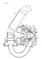
- Fig. 1 is a partially broken-away front view of a four-stroke cycle engine according to embodiment 1 of this invention
- Fig. 2 a front view of the upper part of the engine
- Fig. 3 a partial plan view of the cylinder head of the engine
- Fig. 4 a partial sectional side view of the upper part of the engine.
- the four-stroke cycle engine 1 of this embodiment is of a four-valve four-cylinder type for automobiles; as shown in Fig. 1, a cylinder head 2 is formed with two intake passages 3 and two exhaust passages 4 for each cylinder (only one intake passage and exhaust passage are shown in Fig. 1); and intake ports 3a and exhaust ports 4a at which the intake and exhaust passages 3, 4 are open to a combustion chamber S, are opened and closed by intake and exhaust valves 5, 6 at appropriate timings, respectively, for required gas exchange.
- the intake and exhaust valves 5, 6 are inserted for sliding movement to the valve guides 7, 8 press-fitted in the cylinder head 2, respectively, biased toward valve closing by valve springs 9 10, and engaged with intake cams 13a and exhaust cams 14a through valve lifters 11, 12, respectively.
- the intake and exhaust cams 13a, 14a are formed on an intake cam shaft 13 and an exhaust cam shaft 14 integrally therewith; the intake and exhaust cam shafts 13, 14 are driven for rotation to open and close the intake and exhaust valves 5, 6 at appropriate timings, respectively, as described above; and at one end of the intake and exhaust cam shafts 13, 14 are attached variable valve timing devices (hereinafter referred to as VVTs) 15, 16 for changing the opening and closing timing of the intake and exhaust valves 5, 6, respectively (see Figs. 1 and 2).
- VVTs variable valve timing devices
- Timing belts (not shown) are wound around timing pullies 15a, 16a provided on the VVTs 15, 16, respectively.
- a cam cover 17 is attached to the top of the cylinder head 2; a cylinder block (not shown) is fixed to the bottom of the cylinder head 2; and a piston (not shown) is fitted for sliding movement in each of four cylinder (not shown) provided, in parallel and in the direction perpendicular to the sheet plane of Fig. 1, in the cylinder block.
- an ignition plug In the center of each cylinder in the cylinder head 2 is screwed an ignition plug (not shown) and on the intake air side is attached an injector (not shown) for injecting fuel into the intake passages 3.
- the cam cover 17 is formed, at the top, with a surge tank 18 integrally therewith; laterally centrally of one end wall of the surge tank 18 is connected an air cleaner 20 through a throttle body 19; and four intake manifolds 21 pass through the other end of the surge tank 18.
- One end in the shape of a bellmouth of the intake manifold is open to the surge tank 18 and the other end thereof is connected to the intake passages 3 formed in the cylinder head 2.
- a throttle valve 22 In the throttle body 19 is provided a throttle valve 22.
- the intake and exhaust cam shafts 13, 14 are supported for rotation on cam journal sections formed on the top surface of the cylinder head 2, respectively, the upper halves thereof being hold by cam caps bolted to the cam journal sections; and as shown in Figs. 2-4, on the top surface of the cylinder head 2 on the side at which the WTs 15, 16 are attached, is mounted an integral cam cap 23 common to the intake and exhaust cam shafts 13, 14.
- a single oil passage 28 in the vertical direction in which is provided a detachable oil filter 29.
- This oil passage 28 is connected, as shown in Fig. 3, to the control valves 24, 25 through an oil passage 30 formed horizontally in the integral cam cap 23 and oil passages 31 branched off laterally from the oil passage 30.
- the lower end of the oil passage 28 is in communication with an oil passage 32 provided horizontally in the cylinder head 2.
- the integral cam cap 23 is formed with a plurality of oil passages 33, 34, 35, 36 through which controlling oil is supplied from the control valves 24, 25 to the respective VVTs 15, 16, and these oil passages 33-36 are in communication with oil pressure chambers of the VVTs 15, 16 through ring grooves formed in the outside circumferences of the intake and exhaust cam shafts 13, 14 and oil holes 13b, 14b (see Fig. 2) formed in the intake and exhaust cam shafts 13, 14 along their axial centers.
- the two control valves 24, 25 and the oil filter 29 are disposed outside of the cam chamber Si inside the cam cover 17 and of the cam belt chamber S2 inside the belt cover 26.
- the exhaust valves 6 When the piston approaches the bottom dead center, the exhaust valves 6 are opened, exhaust gas at an elevated temperature and pressure, generated by the combustion of the mixture in the combustion chamber S, is discharged from the exhaust ports 4a to the exhaust passages 4 in the exhaust stroke where the piston ascends, and then through the exhaust manifold (not shown) connected to the exhaust passages 4 into the atmosphere.
- oil supplied by an oil pump flows from the oil passage 32 (see Fig. 2) formed in the cylinder head 2, to the oil passage 28, and after purified through the oil filter 29, it is supplied from the oil passage 28 through the oil passages 30, 31 (see Fig. 3) into each of the two control valves 24, 25.
- oil supplied to the control valves 24, 25 through a single oil passage 28 running between the intake and exhaust cam shafts 13, 14, the single oil passage 28 is utilized in common to the two control valves 24, 25.
- the oil which has been supplied to each of the control valves 24, 25, is controlled of its pressure by the respective control valves 24, 25, and supplied as controlling oil to the respective VVTs 15, 16 through the oil passages 33-36 for variable control of the opening and closing timing of the intake and exhaust valves 5, 6 by the VVTs 15, 16, and to the journal sections of the intake and exhaust cam shafts 13, 14 for lubrication thereof.
- the two control valves 24, 25 are disposed vertically between the intake and exhaust cam shafts 13, 14, therefore these control valves 24, 15 can be disposed compactly within the dimension of the existing cylinder head 2, effecting size reduction of the four-stroke cycle engine 1.
- control valves 24, 25 and the oil filter 29 are disposed outside of the cam chamber 51 inside the cam cover 17 and of the cam belt chamber S2 inside the belt cover 26, therefore maintenance, such as regulation or replacement, of the control valves 24, 25 and the oil filter 29 can be performed easily, with the cam cover 17 and the belt cover 26 not removed and left in place, and high sealing ability of the control valves 24, 25 can be assured.
- the single oil passage 28 is provided between the two control valves 24, 25 for common use thereto, the structure of oil passages including the oil passage 28 is simplified, effecting higher variable control response of the opening and closing timing of the intake and exhaust valves 5, 6.
- Fig. 5 is a partial plan view of the cylinder head of a four-stroke cycle engine according to embodiment 2 of this invention.
- like parts as shown in Fig. 3 are designated by like numerals, and description is omitted of these parts.
- the oil filter 29 is disposed in the cam belt chamber S2 (that is, the oil filter 29 is disposed on the opposite side of the sealing wall 23a of the integral cam cap 23 from the control valves 24, 25), other structures are the same as those in the foregoing embodiment 1.
- the oil filter 29 is disposed in the cam belt chamber S2, therefore the sealing wall 23a of the integral cam cap 23 constituting the sealing surface of the belt cover (not shown), can be formed straight as shown in the figure, thereby simplifying the structure as well as effecting higher sealing ability of the belt cover.
- Embodiment 3 according to the present invention will be described next with reference to Fig. 6.
- Fig. 6 is a partial plan view of the cylinder head of a four-stroke cycle engine associated with the embodiment 3 of the present invention. Also, in this drawing, the same reference numerals are given to the identical elements as illustrated in Fig. 3 and the description of those elements will be omitted.
- the sealing wall 23a of the integrated cam cap 23 constituting the sealing surface for the belt cover is formed in linear shape as the above embodiment 2.
- the oil filter 29 and a plurality of holes 37 for the cam cap bolt are placed on the rear part of the engine (the right hand side of Fig. 6) with respect to the sealing wall 23a, i.e. outside of the cam belt chamber S2.
- the oil filter 29 since the oil filter 29 is arranged outside of the cam belt chamber S2, the oil filter 29 can be replaced as it stands without the need for removing the belt cover in a similar manner to the above embodiment 1. Also, during the replacement of the oil filter 29, the timing belt (not shown ) would not be stained with oil so that life duration of the timing belt is not affected. Since the sealing walls 23a of the integrated cam cap 23 is formed in linear shape as the embodiment 2, simplification of the structure and improvement of the sealing ability of the belt cover can be attained.
- two control valves are disposed outside the cam cover, therefore maintainability and sealing ability of the control valves can be enhanced.
- a single oil passage is provided between the two control valves for common use, therefore oil passages are simplified, effecting higher variable control response of the opening and closing timing of the intake and exhaust valves.
- an oil filter is disposed outside the cam chamber and the cam belt chamber, therefore replacement of the oil filter can be simplified, effecting higher maintainability.
- an oil filter is disposed in the cam belt chamber, therefore the sealing surface of the belt cover can be formed straight, thereby effecting simplified structure as well as improved sealing ability of the belt cover.
Landscapes
- Engineering & Computer Science (AREA)
- Mechanical Engineering (AREA)
- General Engineering & Computer Science (AREA)
- Valve Device For Special Equipments (AREA)
- Valve-Gear Or Valve Arrangements (AREA)
- Cylinder Crankcases Of Internal Combustion Engines (AREA)
Applications Claiming Priority (4)
| Application Number | Priority Date | Filing Date | Title |
|---|---|---|---|
| JP15264299 | 1999-05-31 | ||
| JP15264299 | 1999-05-31 | ||
| JP29394899 | 1999-10-15 | ||
| JP29394899A JP2001050102A (ja) | 1999-05-31 | 1999-10-15 | 4サイクルエンジン |
Publications (2)
| Publication Number | Publication Date |
|---|---|
| EP1057982A2 true EP1057982A2 (fr) | 2000-12-06 |
| EP1057982A3 EP1057982A3 (fr) | 2002-08-14 |
Family
ID=26481499
Family Applications (1)
| Application Number | Title | Priority Date | Filing Date |
|---|---|---|---|
| EP00111670A Withdrawn EP1057982A3 (fr) | 1999-05-31 | 2000-05-31 | Moteur à quatre temps |
Country Status (3)
| Country | Link |
|---|---|
| US (1) | US6289861B1 (fr) |
| EP (1) | EP1057982A3 (fr) |
| JP (1) | JP2001050102A (fr) |
Cited By (6)
| Publication number | Priority date | Publication date | Assignee | Title |
|---|---|---|---|---|
| EP1316682A3 (fr) * | 2001-11-30 | 2003-12-03 | Yamaha Hatsudoki Kabushiki Kaisha | Culasse pour un moteur à combustion interne |
| EP1422387A1 (fr) * | 2002-11-14 | 2004-05-26 | Mazda Motor Corporation | Système variateur de phase de moteur |
| EP1640570A1 (fr) * | 2004-09-27 | 2006-03-29 | Aisin Seiki Kabushiki Kaisha | Unité de vanne électromagnétique et couvercle pour moteur à combustion interne |
| WO2006085640A1 (fr) * | 2005-02-10 | 2006-08-17 | Toyota Jidosha Kabushiki Kaisha | Structure de fixation de capteur pour moteur a combustion interne et capuchon de came |
| WO2008026057A3 (fr) * | 2006-08-31 | 2008-05-02 | Toyota Motor Co Ltd | Coiffe de came |
| DE102005048732B4 (de) | 2005-10-12 | 2024-07-25 | Schaeffler Technologies AG & Co. KG | Elektromagnetische Stelleinheit eines hydraulischen Wegeventils |
Families Citing this family (22)
| Publication number | Priority date | Publication date | Assignee | Title |
|---|---|---|---|---|
| JP3561467B2 (ja) * | 2000-10-25 | 2004-09-02 | 本田技研工業株式会社 | エンジンの動弁制御装置 |
| JP4517514B2 (ja) * | 2001-02-14 | 2010-08-04 | マツダ株式会社 | 内燃機関の可変バルブタイミング機構への給油装置 |
| DE10118119C2 (de) * | 2001-04-11 | 2003-11-20 | Ina Schaeffler Kg | Brennkraftmaschine mit zwei in deren Zylinderkopf nebeneinander angeordneten Nockenwellen, insbesondere mit einer Einlass- und einer Auslassnockenwelle |
| JP2003003870A (ja) * | 2001-06-21 | 2003-01-08 | Sanshin Ind Co Ltd | 船外機用4サイクルエンジンのバルブタイミング制御装置 |
| JP2003013759A (ja) | 2001-06-29 | 2003-01-15 | Sanshin Ind Co Ltd | 船外機用4サイクルエンジンのバルブタイミング制御装置 |
| JP2003013760A (ja) | 2001-07-02 | 2003-01-15 | Sanshin Ind Co Ltd | 船外機用4サイクルエンジンのバルブタイミング制御装置 |
| JP2003013761A (ja) | 2001-07-02 | 2003-01-15 | Sanshin Ind Co Ltd | 船外機用4サイクルエンジンのバルブタイミング制御装置 |
| JP2003020964A (ja) | 2001-07-04 | 2003-01-24 | Sanshin Ind Co Ltd | 船外機用4サイクルエンジンのバルブタイミング制御装置 |
| JP2003035156A (ja) | 2001-07-25 | 2003-02-07 | Sanshin Ind Co Ltd | 船外機用4サイクルエンジン |
| JP2003035179A (ja) | 2001-07-25 | 2003-02-07 | Sanshin Ind Co Ltd | 船外機用4サイクルエンジン |
| JP3966003B2 (ja) * | 2002-02-05 | 2007-08-29 | 日産自動車株式会社 | 内燃機関 |
| DE10307624A1 (de) * | 2003-02-22 | 2004-09-02 | Daimlerchrysler Ag | Vorrichtung zur relativen Drehwinkeländerung einer Nockenwelle zu einem Antriebsrad einer Brennkraftmaschine |
| DE10307623A1 (de) * | 2003-02-22 | 2004-09-02 | Daimlerchrysler Ag | Vorrichtung zur relativen Drehwinkeländerung einer Nockenwelle zu einem Antriebsrad einer Brennkraftmaschine |
| JP4137019B2 (ja) * | 2004-07-05 | 2008-08-20 | トヨタ自動車株式会社 | 樹脂製シリンダヘッドカバー |
| JP4118262B2 (ja) * | 2004-07-14 | 2008-07-16 | トヨタ自動車株式会社 | バルブケース及び樹脂製シリンダヘッドカバー |
| KR20060015005A (ko) * | 2004-08-13 | 2006-02-16 | 현대자동차주식회사 | 엔진의 연속가변밸브타이밍장치용 오일필터 |
| JP4873243B2 (ja) * | 2007-03-08 | 2012-02-08 | スズキ株式会社 | 可変バルブタイミング機構付エンジン |
| US20090186725A1 (en) * | 2008-01-18 | 2009-07-23 | Joseph Jouraij | Multi-utility camshaft cap for internal combustion engine |
| US9027522B2 (en) | 2012-10-17 | 2015-05-12 | Ford Global Technologies, Llc | Camshaft with internal oil filter |
| JP5779222B2 (ja) | 2013-11-08 | 2015-09-16 | 本田技研工業株式会社 | オイルコントロールバルブの保持構造 |
| US9797280B2 (en) | 2015-10-09 | 2017-10-24 | Ford Global Technologies, Llc | Camshaft thrust bearing lubrication system |
| JP7528766B2 (ja) * | 2020-12-15 | 2024-08-06 | スズキ株式会社 | 内燃機関 |
Family Cites Families (7)
| Publication number | Priority date | Publication date | Assignee | Title |
|---|---|---|---|---|
| JP3189679B2 (ja) * | 1996-05-24 | 2001-07-16 | トヨタ自動車株式会社 | 内燃機関のバルブ特性制御装置 |
| JPH1089024A (ja) * | 1996-09-13 | 1998-04-07 | Toyota Motor Corp | 内燃機関のバルブ特性可変機構 |
| JPH10184323A (ja) * | 1996-12-26 | 1998-07-14 | Yamaha Motor Co Ltd | 4サイクルエンジン |
| JP3847428B2 (ja) * | 1997-11-19 | 2006-11-22 | ヤマハ発動機株式会社 | 内燃エンジンのシリンダヘッド構造 |
| JP4036401B2 (ja) * | 1998-03-27 | 2008-01-23 | ヤマハ発動機株式会社 | 可変バルブタイミング装置を備えた4サイクルエンジン |
| JP4229501B2 (ja) * | 1998-11-13 | 2009-02-25 | ヤマハ発動機株式会社 | エンジンのオイルコントロールバルブ配置構造 |
| EP1046793A3 (fr) * | 1999-04-21 | 2002-08-21 | Ford Global Technologies, Inc. | Dispositif de calage de soupape variable et méthode |
-
1999
- 1999-10-15 JP JP29394899A patent/JP2001050102A/ja active Pending
-
2000
- 2000-05-02 US US09/562,001 patent/US6289861B1/en not_active Expired - Lifetime
- 2000-05-31 EP EP00111670A patent/EP1057982A3/fr not_active Withdrawn
Non-Patent Citations (1)
| Title |
|---|
| None |
Cited By (8)
| Publication number | Priority date | Publication date | Assignee | Title |
|---|---|---|---|---|
| EP1316682A3 (fr) * | 2001-11-30 | 2003-12-03 | Yamaha Hatsudoki Kabushiki Kaisha | Culasse pour un moteur à combustion interne |
| EP1422387A1 (fr) * | 2002-11-14 | 2004-05-26 | Mazda Motor Corporation | Système variateur de phase de moteur |
| US6860247B2 (en) | 2002-11-14 | 2005-03-01 | Mazda Motor Corporation | Engine variable valve timing system |
| EP1640570A1 (fr) * | 2004-09-27 | 2006-03-29 | Aisin Seiki Kabushiki Kaisha | Unité de vanne électromagnétique et couvercle pour moteur à combustion interne |
| WO2006085640A1 (fr) * | 2005-02-10 | 2006-08-17 | Toyota Jidosha Kabushiki Kaisha | Structure de fixation de capteur pour moteur a combustion interne et capuchon de came |
| DE102005048732B4 (de) | 2005-10-12 | 2024-07-25 | Schaeffler Technologies AG & Co. KG | Elektromagnetische Stelleinheit eines hydraulischen Wegeventils |
| WO2008026057A3 (fr) * | 2006-08-31 | 2008-05-02 | Toyota Motor Co Ltd | Coiffe de came |
| US8042509B2 (en) | 2006-08-31 | 2011-10-25 | Toyota Jidosha Kabushiki Kaisha | Cam cap |
Also Published As
| Publication number | Publication date |
|---|---|
| EP1057982A3 (fr) | 2002-08-14 |
| JP2001050102A (ja) | 2001-02-23 |
| US6289861B1 (en) | 2001-09-18 |
Similar Documents
| Publication | Publication Date | Title |
|---|---|---|
| EP1057982A2 (fr) | Moteur à quatre temps | |
| US6286467B1 (en) | Two stroke engine conversion | |
| JPH10184323A (ja) | 4サイクルエンジン | |
| EP1179676A1 (fr) | Moteur à combustion interne à injection directe | |
| MXPA00006794A (es) | Motor de combustion interna con cabeza de cilindros en forma de cuna y multiple de admision integral. | |
| US7412949B1 (en) | Dual head piston engine | |
| JP2003519314A (ja) | バルブ制御を有する内燃機関 | |
| KR100330300B1 (ko) | 기통내분사형불꽃점화식내연엔진 | |
| EP1148217A2 (fr) | Dispositif de commande d'admission pour un moteur à combustion interne | |
| US6189503B1 (en) | Porting arrangement for direct injected engine | |
| JP2820793B2 (ja) | ポンプシリンダと動力シリンダを備えたレシプロエンジン | |
| EP1148214A1 (fr) | Moteur à combustion interne avec une pompe à huile | |
| US6234120B1 (en) | Two-stroke engine | |
| EP0971116B1 (fr) | Moteur à combustion interne | |
| KR950001325B1 (ko) | 2행정 엔진 | |
| US5870980A (en) | Stepped piston internal combustion engine | |
| US5070834A (en) | Diesel engine with a precombustion chamber | |
| US6145483A (en) | Two-cycle internal combustion engine | |
| EP1273784B1 (fr) | Culasse pour un moteur à combustion interne à quatre temps | |
| US6516764B2 (en) | Camshaft supporting structure for four-stroke cycle engine | |
| JPH0121326B2 (fr) | ||
| CN100400813C (zh) | 发动机 | |
| CN223256952U (zh) | 一种单缸缸内直喷气缸头 | |
| JPH0120288B2 (fr) | ||
| US2117551A (en) | Valve mechanism |
Legal Events
| Date | Code | Title | Description |
|---|---|---|---|
| PUAI | Public reference made under article 153(3) epc to a published international application that has entered the european phase |
Free format text: ORIGINAL CODE: 0009012 |
|
| AK | Designated contracting states |
Kind code of ref document: A2 Designated state(s): AT BE CH CY DE DK ES FI FR GB GR IE IT LI LU MC NL PT SE |
|
| AX | Request for extension of the european patent |
Free format text: AL;LT;LV;MK;RO;SI |
|
| PUAL | Search report despatched |
Free format text: ORIGINAL CODE: 0009013 |
|
| AK | Designated contracting states |
Kind code of ref document: A3 Designated state(s): AT BE CH CY DE DK ES FI FR GB GR IE IT LI LU MC NL PT SE |
|
| AX | Request for extension of the european patent |
Free format text: AL;LT;LV;MK;RO;SI |
|
| RIC1 | Information provided on ipc code assigned before grant |
Free format text: 7F 01L 1/344 A, 7F 01L 1/26 B, 7F 01L 1/46 B, 7F 01L 1/34 B, 7F 02D 13/02 B |
|
| AKX | Designation fees paid | ||
| REG | Reference to a national code |
Ref country code: DE Ref legal event code: 8566 |
|
| STAA | Information on the status of an ep patent application or granted ep patent |
Free format text: STATUS: THE APPLICATION IS DEEMED TO BE WITHDRAWN |
|
| 18D | Application deemed to be withdrawn |
Effective date: 20030215 |