EP1058065B1 - Schleuse für Reinraum-Anlagen - Google Patents
Schleuse für Reinraum-Anlagen Download PDFInfo
- Publication number
- EP1058065B1 EP1058065B1 EP00110416A EP00110416A EP1058065B1 EP 1058065 B1 EP1058065 B1 EP 1058065B1 EP 00110416 A EP00110416 A EP 00110416A EP 00110416 A EP00110416 A EP 00110416A EP 1058065 B1 EP1058065 B1 EP 1058065B1
- Authority
- EP
- European Patent Office
- Prior art keywords
- air
- lock
- air lock
- chamber
- overflow
- Prior art date
- Legal status (The legal status is an assumption and is not a legal conclusion. Google has not performed a legal analysis and makes no representation as to the accuracy of the status listed.)
- Expired - Lifetime
Links
Images


Classifications
-
- F—MECHANICAL ENGINEERING; LIGHTING; HEATING; WEAPONS; BLASTING
- F24—HEATING; RANGES; VENTILATING
- F24F—AIR-CONDITIONING; AIR-HUMIDIFICATION; VENTILATION; USE OF AIR CURRENTS FOR SCREENING
- F24F9/00—Use of air currents for screening, e.g. air curtains
-
- F—MECHANICAL ENGINEERING; LIGHTING; HEATING; WEAPONS; BLASTING
- F24—HEATING; RANGES; VENTILATING
- F24F—AIR-CONDITIONING; AIR-HUMIDIFICATION; VENTILATION; USE OF AIR CURRENTS FOR SCREENING
- F24F3/00—Air-conditioning systems in which conditioned primary air is supplied from one or more central stations to distributing units in the rooms or spaces where it may receive secondary treatment; Apparatus specially designed for such systems
- F24F3/12—Air-conditioning systems in which conditioned primary air is supplied from one or more central stations to distributing units in the rooms or spaces where it may receive secondary treatment; Apparatus specially designed for such systems characterised by the treatment of the air otherwise than by heating and cooling
- F24F3/16—Air-conditioning systems in which conditioned primary air is supplied from one or more central stations to distributing units in the rooms or spaces where it may receive secondary treatment; Apparatus specially designed for such systems characterised by the treatment of the air otherwise than by heating and cooling by purification, e.g. by filtering; by sterilisation; by ozonisation
- F24F3/167—Clean rooms, i.e. enclosed spaces in which a uniform flow of filtered air is distributed
Definitions
- the invention relates to a lock for clean room systems with a limited by two side walls and two door inserts, with a floor and ceiling enclosed lock room with essentially cylindrical cross-section of air in the manner of a swirling flow is flowed through, wherein one of the side walls outflow opening / -gen and in the ceiling and / or floor area respectively Overflow provided for the air flowing through the lock chamber are, as well as with an inflow and a return air chamber.
- the lock itself consists of two double-walled side walls and two door panels constructed, the inner walls together with a Ceiling and a bottom closure delimit the lock room.
- the one of the side walls is designed as an inflow chamber whose inner wall the wall of the lock chamber is; the outer wall of this inflow chamber has at least one air-permeable area, the is designed as a filter wall. Through this filter wall, air in pour in the lock system, which is cleaned in the filter and so on is supplied with the required cleanliness of the lock.
- the other The side walls form an overflow channel for the air, which in Bottom area extracted and the return air chamber above the ceiling, on a blower with in the return air chamber led intake is attached, flows, with its inner wall, the lock chamber also limited.
- the inner walls of both the inflow chamber and the Overflow channels form with their circular segment-like shape essentially cylindrical basic shape of the lock chamber.
- there only has the inner wall of the inflow at least one at least over a part of their height extending, substantially paraxial Outflow opening.
- several are slit-shaped Outflow openings are provided, which are then parallel to the axis of the Interior of the lock are aligned.
- Advantageous is / are these Outflow opening / gene off-center on the inner wall to one of Door inserts arranged offset. It is advantageous if the outflow opening (s) are displaced towards the door insert, the the door panel associated with the clean room opposite or at an angle is arranged horizontally. By this shift up close to the Door insert, into the passage into, remindströmwirbel be avoided and Nachströmungen in the region of the cylindrical interior suppressed.
- the two side walls can through each other opposite arranged door panels against each other at a distance be held so that sidewalls and door panels in pairs are arranged opposite each other and a straight passage lock form. Since only one of the side walls of the lock space, namely, the inner wall of the inflow chamber at least one outflow opening can be located next to this straight through lock also create corner or angle locks with angled passage, without making any changes to the basic concept have to.
- the advantage here is the Door insert through which the clean room is reached, immediately on the arranged substantially cylindrical interior. This connects the door the insides of both side walls without substantial shock, so that in this area a smooth flow transition can take place.
- the outer wall of the inflow chamber is provided with an air-permeable area, which as Filter wall is formed.
- Filter wall is formed.
- outflow openings can arranged a number of in an axis-parallel flight Single openings may be provided, for example, rounded or may be rectangular in shape; alternatively, the Outflow opening of at least one substantially slit-shaped Formed opening whose total area is such that the desired exit velocity is obtained.
- the Outflow advantageously arranged so that their height at most 75% of the height of the cylindrical interior of the lock is.
- the suction of the air from the lock takes place both through the Ceiling and ground near by overflow openings.
- To a close to the ceiling as well as a near-ground suction to allow forms the others of the air chambers have an overflow channel, one under the floor formed or near the ground provided return flow chamber with a return air chamber connects above the ceiling.
- One of the overflow openings, preferably in the ceiling is formed by an inlet nozzle, while the other overflow opening, preferably the ground level, forms an annular gap.
- the surfaces of this are advantageous Overflow openings approximately equal to the area of the outflow opening / gen.
- a bottom-return flow chamber arranged and in the ground Annular gap provided, which - apart from supporting struts - a full circle forms.
- the extracted air flows through this annular gap in the bottom return chamber and on through the overflow channel in the return air chamber above the ceiling.
- a second embodiment is for near-bottom suction in the inner wall of the Overflow chamber forming side wall arranged annular gap provided. This annular gap forms a horizontally extending, just above lying on the ground circle segment and directs the emerging from the lock Air in a near-ground return chamber.
- the air is sucked out of the lock chamber, that one of the overflow openings with a much larger volume flow is charged; as advantageous have divisions in the range of 60%: 40% to 90%: 10%.
- the air flow in the lock is through causes a blower, which is placed on the lock and air sucks through the overflow from the lock.
- the outflow opening in the inner wall of the inflow chamber off-center to one of Door inserts arranged offset, so that the outflowing air not aimed at the center of the lock room.
- the whole Surface of the outflow opening / -gen is chosen so that this desired exit velocity is achieved.
- the outflow opening is preferably to the side arranged offset those of the overflow, over the the larger volume flow is removed.
- the displacement equivalent is also an extension provided in Ver GmbHsscardi the surface of the discharge opening, which is at a slot-shaped Outflow opening by wedge shape or in single openings by increase their area or by decreasing the distances between them reached becomes.
- the surfaces of the overflow openings are so each other in proportion, as is the ratio of the two volume flows equivalent.
- the blowout of the blower opens in a transfer channel, with a filter wall covering the Air chamber is connected and through which sucked out of the lock Air blown as circulating air in this air chamber and in the filter wall is cleaned, and so again goes to the lock.
- the recirculation channel is advantageously provided with outflow means, Furthermore, inflow openings are provided, for the purpose of flowing off Air. This allows a partial exchange of air, it being According to the method sufficient, if - depending on the load of the lock - 5% to 20% of the circulated air, in particular to dissipate the heat loss of the blower, discharged and replaced by as much supply air becomes.
- the outflow means are adjustable. preferably designed adjustable adjustable; as a controlled variable For example, the air temperature can be selected.
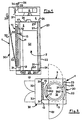
- Figures 1, 2 and 3 show the designed for cleanroom use Lock 1, which is designed here as a straight-through passage lock is.
- the side walls of the lock 1 are from a Zu Kunststoffsch 10, an overflow chamber 20 and two door inserts 5 'and 5 '' formed, of which a door insert 5 'the (not shown) Cleanroom is assigned while the other door panel 5 '' this opposite or lying at an angle arranged access forms.
- the so conceived Sluice 1 can also be constructed as a corner lock (FIG.
- FIG. 1b shows an alternative embodiment: Here is the overflow opening 26.2 not provided in the ground, but near the ground in the inner wall 21 of the overflow forming side wall 20. In this embodiment can be dispensed to the bottom-return chamber 25 what simplification of construction and exhibition means.
- the ceiling of the lock 1 is formed by a return air chamber 4, whose the wall facing the lock 4.1 with an inlet nozzle 28 formed overflow opening is provided, and on a blower attachment 6 is attached, the impeller 6.1 - here one without drive drawn free-runner - drawing in air; this is the suction 7 in the Return air chamber 4 out.
- a second suction is under the floor the lock 1 provided; the bottom is from a bottom return chamber 25 formed, the cover 25.1 the bottom of the interior of the second the lock forms.
- the provided in this cover 25.1 of the floor Overflow 26.1 is designed here as an annular gap, which apart from radial support struts - forms a full circle.
- the overflow channel 23 has both the bottom return chamber 25 as also to the return air chamber 4 openings 24 through which the air on or can flow out.
- the so extracted from the fan 6 air is released into the environment blown out.
- blow 8 of the blower 6 are here at least one of the sides of the fan attachment 6 arranged grid provided.
- the forming in the interior 2 of the lock 1 negative pressure allows air from the inflow chamber 10 via outflow 18 get into the interior 2; in this, they overlap each other close to the ceiling and the near-bottom lowering flows of the overflow openings 28 in the ceiling 26.1 or 26.2 in the floor area, and force the inflowing air into the swirl flow.
- the inflow chamber 10 has a lock interior 2 limiting Inner wall 11 with niksegmetartigen formations 11.1, so that the cross-section of the interior 2 is substantially cylindrical represents.
- the outer wall 12 has an air-permeable area 14, in which a filter 15 of sufficient filter quality arranged Ensuring that the inflowing air is the required Purity has.
- the subsequent flow is via the Outflow openings 17 ( Figures 2, 3: drawn as a double line; s. Fig. 6).
- the overflow 26.1 - here only in the area the bottom cover 25.1 shown - is designed as an annular gap, which runs near the circular segment-like formations 21.1.
- the provided in the ceiling area overflow 28 - not closer shown - is designed as a central overflow: they is advantageous by means of a known from fans ago inlet nozzle educated. It goes without saying that the annular gap-shaped Overflow opening also in the ceiling area and / or the central Overflow opening can be provided in the bottom area.
- FIG. 4 and 5 show a trained as a recirculation unit lock 1, whose construction of the exhaust air lock according to Fig. 1-3 corresponds.
- the inflow chamber forming side wall 10 To the inflow chamber forming side wall 10 is the circulating air chamber 30 so provided that they the air-permeable region 14 of the outer wall 12th covered with the filter 15 used.
- the over the exhaust opening 34 outflowing air enters the interior of the circulating air chamber 30 and flows from there through the air-permeable area 14 provided Filter 15 in the inflow chamber 10 and from there also in the above Through the lock 1.
- An inclined air distributor 33 can be provided. In order to prevent heating up, for example due to the waste heat of the blower, a part of the circulated air is discharged.
- FIGS. 6a-6c show various embodiments of the outflow openings 17, where the representation here also the off-center arrangement the outflow opening 17 can be seen:
- the alignment line of the outflow - dash-dotted lines - is located away from the center line - long / short dashed lines indicated - the inner wall 11 of Side wall 10.
- This outflow opening 17 may also be of a number of vertical Escape arranged individual openings to be formed (Fig. 6b).
- the continuous slot can also be in the form of two (or more) be formed next to each other lying slits ( Figure 6c).
Landscapes
- Engineering & Computer Science (AREA)
- Chemical & Material Sciences (AREA)
- Combustion & Propulsion (AREA)
- Mechanical Engineering (AREA)
- General Engineering & Computer Science (AREA)
- Ventilation (AREA)
- Devices For Use In Laboratory Experiments (AREA)
Description
- Fig. 01:
- Schleuse mit Abluft (Ansicht - geschnitten),
Fig. 1a: Boden-Überströmöffnung als Ringspalt in dem Boden:
Fig. 1b: Boden-Überströmöffnung als Ringspalt in der die bodennahe Überströmkammer bildende Seitenwand: - Fig, 02:
- Schleuse mit Abluft, Durchgangsschleuse, (Aufsicht - geschnitten);
- Fig. 03:
- Schleuse mit Abluft, Eckschleuse, (Aufsicht - geschnitten);
- Fig. 04:
- Schleuse mit Umluft (Ansicht - geschnitten);
- Fig. 05:
- Schleuse mit Umluft (Aufsicht - geschnitten);
- Fig. 06:
- Seitenwand mit Zuströmkammer und Ausströmöffnung
(Schema-Darstellung ohne Türeinsatz).
Fig. 6a: Ausströmöffnung als fluchtende Lochreihe,
Fig. 6b: Ausströmöffnung als Doppelschlitz,
Fig. 6c: Ausströmöffnung als höhenversetzer Einzelschlitz.
Claims (17)
- Schleuse für Reinraum-Anlagen mit einem von jeweils zwei Seitenwänden und zwei Türeinsätzen begrenzten, mit einem Boden und einer Decke abgeschlossenen Schleusenraum mit im wesentlichen zylindrischen Querschnitt, der von Luft in Art einer Drallströmung durchströmt ist, wobei eine der Seitenwände Ausströmöffnung/-gen aufweist und im Decken- und/oder im Bodenbereich jeweils Überströmöffnungen für die den Schleusenraum durchströmende Luft vorgesehen sind, sowie mit einer Zuström- und einer Rückluftkammer, wobei die eine Seitenwand als Zuströmkammer (10) ausgebildet ist, deren kreissegmentartig ausgeformte Innenwand (11) den Schleusenraum (2) begrenzend mindestens eine im wesentlichen achsparallele, über zumindest einen Teil ihrer Höhe verlaufende Ausströmöffnung (17) und deren Außenwand (12) mindestens einen luftdurchlässigen. Bereich (14) aufweisen, dass die andere, kreissegmentartig ausgeformte Seitenwand eine vom Bodenbereich zur Rückluftkammer (4) oberhalb der Decke (4.1) führenden Überströmkanal (23) für die Luft bildet, deren Innenwand (21) den Schleusenraum begrenzt, und dass auf die Rückluftkammer (4) ein Gebläse (6) mit in diese geführtem Ansaug (7) aufgesetzt ist.
- Schleuse nach Anspruch 1, dadurch gekennzeichnet, dass der luftdurchlässige Bereich als Filterwand (15) ausgebildet ist.
- Schleuse nach Anspruch 1 oder 2, gekennzeichnet durch paarweise einander gegenüber liegend oder paarweise im Winkel zueinander angeordnete Türeinsätze (5; 5', 5''), sowie Zuströmkammer- bzw. Überströmkanal-Seitenwände (10; 20), zur Bildung einer geraden Durchgangsschleuse oder zur Bildung einer Winkel- oder Eckschleuse.
- Schleuse nach Anspruch 3, dadurch gekennzeichnet, dass der dem Reinraum zugeordnete Türeinsatz (5') unmittelbar am Schleusenraum (2) vorgesehen ist, so dass die Tür des Türeinsatzes (5') ohne wesentlichen Stoß in die kreissegmentartig ausgebildeten Seitenwände des Schleusenraumes (2) übergeht.
- Schleuse nach einem der Ansprüche 1 bis 4, gekennzeichnet durch mindestens eine im wesentlichen schlitzförmige Öffnung als Ausströmöffnung (17), wobei vorzugsweise eine Anzahl von in einer achsparallelen Flucht angeordnet sind.
- Schleuse nach einem der Ansprüche 1 bis 5, dadurch gekennzeichnet, dass die Ausströmöffnung (17) außermittig zu einem der Türeinsätze (5), vorzugsweise zu der dem Reinraum abgewandten Seite zugeordnete der Türeinsätze (5'') hin versetzt angeordnet ist.
- Schleuse nach einem der Ansprüche 1 bis 6, gekennzeichnet durch die Höhe der Ausströmöffnung (17) von höchstens 75% der Höhe des Schleusenraumes (2) ist.
- Schleuse nach einem der Ansprüche 1 bis 7, gekennzeichnet durch eine Gesamt-Fläche der Ausströmöffnung (17), die dert bemessen ist, dass die Austrittsgeschwindigkeit der Luft im Bereich von 5 m/s bis 25 m/s liegt.
- Schleuse nach einem der Ansprüche 1 bis 8, dadurch gekennzeichnet, dass die eine der Überströmöffnungen (26.1; 26.2; 28) als Einlaufdüse ausgebildet ist.
- Schleuse nach einem der Ansprüche 1 bis 9, dadurch gekennzeichnet, dass die zweite der Überströmöffnungen (26.1; 26.2; 28) als im Boden (5.1) angeordneter, von radialen Stützstreben abgesehen, einen Vollkreis bildender Ringspalt (26.1) vorgesehen ist, der über eine Boden-Rückströmkammer (25) mit dem Überströmkanal in Strömungsverbindung steht.
- Schleuse nach einem der Ansprüche 1 bis 9, dadurch gekennzeichnet, dass die zweite der Überströmöffnungen (26.1; 26.2; 28) als bodennah in der Innenwand (21) der die Überströmkammer bildenden Seitenwand (20) angeordneter, horizontal verlaufender, der Innenwand (21) entsprechend kreissegmentartig ausgeformter Ringspalt (26.2) ausgebildet ist, der über eine bodennahe Rückströmkammer (25) mit dem Überströmkanal in Strömungsverbindung steht.
- Schleuse nach einem der Ansprüche 1 bis 11, dadurch gekennzeichnet, dass die Fläche der Überströmöffnungen (26.1; 26.2; 28) von Boden und Decke etwa gleich ist der Fläche der Ausströmöffnung/-gen (17).
- Schleuse nach einem der Ansprüche 1 bis 12, dadurch gekennzeichnet, dass die Ausströmöffnung/-gen (17) höhenmäßig zu der Überströmöffnung (26.1; 26.2; 28) versetzt angeordnet ist/sind, die mit dem größeren Absauge-Volumenstrom beaufschlagt ist.
- Schleuse nach einem der Ansprüche 1 bis 13, gekennzeichnet durch Mittel zum Einstellen des Volumenstroms der über die Überströmöffnung im Boden (26.1; 26.2) abgeführten Luft, die vorzugsweise im Bereich der bodennahen Überströmöffnung (26.1; 26.2) vorgesehen sind.
- Schleuse nach einem der Ansprüche 1 bis 13, gekennzeichnet durch Mittel zum Einstellen des Volumenstroms der über die Überströmöffnung im Boden (26.1; 26.2) abgeführten Luft, die vorzugsweise im Bereich der Kanal-Öffnung (24) zum Anschluss an die Rückluftkammer (4), vorgesehen sind.
- Schleuse nach einem der Ansprüche 1 bis 15, dadurch gekennzeichnet, dass der Filterwand (15) der Zuströmkammer (10) eine Umluftkammer (30) vorgeschaltet ist, in die der Ausblas (34) des Gebläses (6) zur Umluftführung mündet, wobei vorzugsweise in der Umluftkammer (30) ein Luftverteileinsatz (33) vorgesehen ist, der schräg so angestellt ist, dass sich der Strömungsquerschnitt von dem Einströmende der Umluftkammer ausgehend verengt.
- Schleuse nach Anspruch 16, dadurch gekennzeichnet, dass das Gebläse (6) eine Abströmöffnung (34) und die Außenwand (32) der Umluftkammer (30) eine Zuströmöffnung (37) aufweisen, wobei die Abströmöffnung (34) und/oder die Zuströmöffung (37) vorzugsweise mit Mitteln zum Einstellen, insbesondere zum Regeln der im Umluftbetrieb ausgeschleusten bzw. zugesetzten Luft versehen ist/sind.
Applications Claiming Priority (2)
| Application Number | Priority Date | Filing Date | Title |
|---|---|---|---|
| DE29909803U DE29909803U1 (de) | 1999-06-04 | 1999-06-04 | Schleuse für Reinraum-Anlagen |
| DE29909803U | 1999-06-04 |
Publications (3)
| Publication Number | Publication Date |
|---|---|
| EP1058065A2 EP1058065A2 (de) | 2000-12-06 |
| EP1058065A3 EP1058065A3 (de) | 2002-12-18 |
| EP1058065B1 true EP1058065B1 (de) | 2005-04-27 |
Family
ID=8074389
Family Applications (1)
| Application Number | Title | Priority Date | Filing Date |
|---|---|---|---|
| EP00110416A Expired - Lifetime EP1058065B1 (de) | 1999-06-04 | 2000-05-16 | Schleuse für Reinraum-Anlagen |
Country Status (3)
| Country | Link |
|---|---|
| EP (1) | EP1058065B1 (de) |
| AT (1) | ATE294362T1 (de) |
| DE (2) | DE29909803U1 (de) |
Family Cites Families (6)
| Publication number | Priority date | Publication date | Assignee | Title |
|---|---|---|---|---|
| US3285693A (en) * | 1966-11-15 | Apparatus for decontaminating personnel | ||
| JPS6071837A (ja) * | 1983-09-29 | 1985-04-23 | Hitachi Plant Eng & Constr Co Ltd | エアシヤワ−装置 |
| JPS62106247A (ja) * | 1985-11-05 | 1987-05-16 | Hitachi Ltd | エアジエツトノズルおよびそれを用いたエアシヤワ−装置 |
| DE3604422A1 (de) * | 1986-02-13 | 1987-08-20 | Kessler & Luch Gmbh | Vorrichtung zum saeubern kontaminierter oberflaechen mittels stroemender luft |
| JPS62225838A (ja) * | 1986-03-26 | 1987-10-03 | Nippon Air Curtain Kk | エア−シヤワ−装置 |
| JP3246182B2 (ja) * | 1994-04-28 | 2002-01-15 | 日立プラント建設株式会社 | エアシャワー装置 |
-
1999
- 1999-06-04 DE DE29909803U patent/DE29909803U1/de not_active Expired - Lifetime
-
2000
- 2000-05-16 AT AT00110416T patent/ATE294362T1/de not_active IP Right Cessation
- 2000-05-16 EP EP00110416A patent/EP1058065B1/de not_active Expired - Lifetime
- 2000-05-16 DE DE50010142T patent/DE50010142D1/de not_active Expired - Lifetime
Also Published As
| Publication number | Publication date |
|---|---|
| EP1058065A2 (de) | 2000-12-06 |
| DE29909803U1 (de) | 2000-08-17 |
| DE50010142D1 (de) | 2005-06-02 |
| ATE294362T1 (de) | 2005-05-15 |
| EP1058065A3 (de) | 2002-12-18 |
Similar Documents
| Publication | Publication Date | Title |
|---|---|---|
| DE69213000T2 (de) | Schirm für Luftreinigung | |
| DE60204477T2 (de) | Zentrifugalabscheider, insbesondere für einen reaktor mit zirkulierendem wirbelbett | |
| DE3304262C2 (de) | Umluft-Abzugshaube | |
| EP0497296A2 (de) | Filter-Ventilator-Einrichtung zur Verwendung bei Reinräumen | |
| DE202018006721U1 (de) | Dunstabzug zum Abzug von auf einem Kochfeld erzeugter Abluft in vertikal unterhalb einer Kochfeldebene weisender Richtung | |
| EP2937015B1 (de) | Arbeitstisch | |
| DE69207056T2 (de) | Verfahren und Vorrichtung für die Belüftung eines Behandlungsraumes | |
| EP0475261B1 (de) | Heizkörper | |
| EP1058065B1 (de) | Schleuse für Reinraum-Anlagen | |
| DE2328186C2 (de) | Induktionsgerät | |
| EP0499813B1 (de) | Gehäuse zur Aufnahme eines Gebläses | |
| DE3235927C1 (de) | Reinraumkammer | |
| DE4103026C1 (de) | ||
| WO2003033852A1 (de) | Glasfront | |
| DE3624541C2 (de) | Vorrichtung zur Wärmeabfuhr aus Geräteeinschüben | |
| DE2536840C2 (de) | ||
| DE2036254C3 (de) | Textilveredlungsmaschine für endloses Fasermaterial | |
| DE4320162C2 (de) | Modul für eine Reinraumdecke | |
| DE102020118766A1 (de) | Plenumsunabhängige modulare Umluftvorrichtung | |
| DE4302990A1 (en) | Air conditioning system for omnibus interior - has flow of air from central roof duct to side outlets above windows | |
| AT207088B (de) | Abschirmung von Raumöffnungen durch einen Luftschleier | |
| DE3832915A1 (de) | Reinraum | |
| EP0366683A1 (de) | Backofen. | |
| DE2419091A1 (de) | Mit transparentem abschlussmittel versehene leuchte | |
| DE102005050010A1 (de) | Lager für in einem Reinraum zu behandelnde Produkte, vorzugsweise Glasscheiben für Flüssigkristallbildschirme , sowie Verfahren zur Reinhaltung von Produkten in einem solchen Lager |
Legal Events
| Date | Code | Title | Description |
|---|---|---|---|
| PUAI | Public reference made under article 153(3) epc to a published international application that has entered the european phase |
Free format text: ORIGINAL CODE: 0009012 |
|
| AK | Designated contracting states |
Kind code of ref document: A2 Designated state(s): AT BE CH CY DE DK ES FI FR GB GR IE IT LI LU MC NL PT SE |
|
| AX | Request for extension of the european patent |
Free format text: AL;LT;LV;MK;RO;SI |
|
| PUAL | Search report despatched |
Free format text: ORIGINAL CODE: 0009013 |
|
| AK | Designated contracting states |
Kind code of ref document: A3 Designated state(s): AT BE CH CY DE DK ES FI FR GB GR IE IT LI LU MC NL PT SE |
|
| AX | Request for extension of the european patent |
Free format text: AL;LT;LV;MK;RO;SI |
|
| RIC1 | Information provided on ipc code assigned before grant |
Free format text: 7F 24F 3/16 A, 7F 24F 9/00 B |
|
| 17P | Request for examination filed |
Effective date: 20030410 |
|
| AKX | Designation fees paid |
Designated state(s): AT BE CH CY DE DK ES FI FR GB GR IE IT LI LU MC NL PT SE |
|
| AXX | Extension fees paid |
Extension state: SI Payment date: 20030410 |
|
| GRAP | Despatch of communication of intention to grant a patent |
Free format text: ORIGINAL CODE: EPIDOSNIGR1 |
|
| GRAS | Grant fee paid |
Free format text: ORIGINAL CODE: EPIDOSNIGR3 |
|
| GRAA | (expected) grant |
Free format text: ORIGINAL CODE: 0009210 |
|
| RAP1 | Party data changed (applicant data changed or rights of an application transferred) |
Owner name: IMTECH DEUTSCHLAND GMBH & CO. KG |
|
| AK | Designated contracting states |
Kind code of ref document: B1 Designated state(s): AT BE CH CY DE DK ES FI FR GB GR IE IT LI LU MC NL PT SE |
|
| AX | Request for extension of the european patent |
Extension state: SI |
|
| PG25 | Lapsed in a contracting state [announced via postgrant information from national office to epo] |
Ref country code: IT Free format text: LAPSE BECAUSE OF FAILURE TO SUBMIT A TRANSLATION OF THE DESCRIPTION OR TO PAY THE FEE WITHIN THE PRESCRIBED TIME-LIMIT;WARNING: LAPSES OF ITALIAN PATENTS WITH EFFECTIVE DATE BEFORE 2007 MAY HAVE OCCURRED AT ANY TIME BEFORE 2007. THE CORRECT EFFECTIVE DATE MAY BE DIFFERENT FROM THE ONE RECORDED. Effective date: 20050427 Ref country code: NL Free format text: LAPSE BECAUSE OF FAILURE TO SUBMIT A TRANSLATION OF THE DESCRIPTION OR TO PAY THE FEE WITHIN THE PRESCRIBED TIME-LIMIT Effective date: 20050427 Ref country code: FI Free format text: LAPSE BECAUSE OF FAILURE TO SUBMIT A TRANSLATION OF THE DESCRIPTION OR TO PAY THE FEE WITHIN THE PRESCRIBED TIME-LIMIT Effective date: 20050427 Ref country code: IE Free format text: LAPSE BECAUSE OF FAILURE TO SUBMIT A TRANSLATION OF THE DESCRIPTION OR TO PAY THE FEE WITHIN THE PRESCRIBED TIME-LIMIT Effective date: 20050427 Ref country code: GB Free format text: LAPSE BECAUSE OF FAILURE TO SUBMIT A TRANSLATION OF THE DESCRIPTION OR TO PAY THE FEE WITHIN THE PRESCRIBED TIME-LIMIT Effective date: 20050427 |
|
| REG | Reference to a national code |
Ref country code: GB Ref legal event code: FG4D Free format text: NOT ENGLISH |
|
| REG | Reference to a national code |
Ref country code: CH Ref legal event code: EP |
|
| PG25 | Lapsed in a contracting state [announced via postgrant information from national office to epo] |
Ref country code: CY Free format text: LAPSE BECAUSE OF FAILURE TO SUBMIT A TRANSLATION OF THE DESCRIPTION OR TO PAY THE FEE WITHIN THE PRESCRIBED TIME-LIMIT Effective date: 20050516 Ref country code: AT Free format text: LAPSE BECAUSE OF NON-PAYMENT OF DUE FEES Effective date: 20050516 Ref country code: LU Free format text: LAPSE BECAUSE OF NON-PAYMENT OF DUE FEES Effective date: 20050516 |
|
| REG | Reference to a national code |
Ref country code: IE Ref legal event code: FG4D Free format text: LANGUAGE OF EP DOCUMENT: GERMAN |
|
| PG25 | Lapsed in a contracting state [announced via postgrant information from national office to epo] |
Ref country code: CH Free format text: LAPSE BECAUSE OF NON-PAYMENT OF DUE FEES Effective date: 20050531 Ref country code: LI Free format text: LAPSE BECAUSE OF NON-PAYMENT OF DUE FEES Effective date: 20050531 Ref country code: MC Free format text: LAPSE BECAUSE OF NON-PAYMENT OF DUE FEES Effective date: 20050531 Ref country code: BE Free format text: LAPSE BECAUSE OF NON-PAYMENT OF DUE FEES Effective date: 20050531 |
|
| REF | Corresponds to: |
Ref document number: 50010142 Country of ref document: DE Date of ref document: 20050602 Kind code of ref document: P |
|
| PG25 | Lapsed in a contracting state [announced via postgrant information from national office to epo] |
Ref country code: GR Free format text: LAPSE BECAUSE OF FAILURE TO SUBMIT A TRANSLATION OF THE DESCRIPTION OR TO PAY THE FEE WITHIN THE PRESCRIBED TIME-LIMIT Effective date: 20050727 Ref country code: SE Free format text: LAPSE BECAUSE OF FAILURE TO SUBMIT A TRANSLATION OF THE DESCRIPTION OR TO PAY THE FEE WITHIN THE PRESCRIBED TIME-LIMIT Effective date: 20050727 Ref country code: DK Free format text: LAPSE BECAUSE OF FAILURE TO SUBMIT A TRANSLATION OF THE DESCRIPTION OR TO PAY THE FEE WITHIN THE PRESCRIBED TIME-LIMIT Effective date: 20050727 |
|
| PG25 | Lapsed in a contracting state [announced via postgrant information from national office to epo] |
Ref country code: ES Free format text: LAPSE BECAUSE OF FAILURE TO SUBMIT A TRANSLATION OF THE DESCRIPTION OR TO PAY THE FEE WITHIN THE PRESCRIBED TIME-LIMIT Effective date: 20050807 |
|
| PG25 | Lapsed in a contracting state [announced via postgrant information from national office to epo] |
Ref country code: PT Free format text: LAPSE BECAUSE OF FAILURE TO SUBMIT A TRANSLATION OF THE DESCRIPTION OR TO PAY THE FEE WITHIN THE PRESCRIBED TIME-LIMIT Effective date: 20051010 |
|
| NLV1 | Nl: lapsed or annulled due to failure to fulfill the requirements of art. 29p and 29m of the patents act | ||
| GBV | Gb: ep patent (uk) treated as always having been void in accordance with gb section 77(7)/1977 [no translation filed] |
Effective date: 20050427 |
|
| BERE | Be: lapsed |
Owner name: IMTECH DEUTSCHLAND G.M.B.H. & CO. KG Effective date: 20050531 |
|
| REG | Reference to a national code |
Ref country code: IE Ref legal event code: FD4D |
|
| REG | Reference to a national code |
Ref country code: CH Ref legal event code: PL |
|
| PLBE | No opposition filed within time limit |
Free format text: ORIGINAL CODE: 0009261 |
|
| STAA | Information on the status of an ep patent application or granted ep patent |
Free format text: STATUS: NO OPPOSITION FILED WITHIN TIME LIMIT |
|
| 26N | No opposition filed |
Effective date: 20060130 |
|
| EN | Fr: translation not filed | ||
| BERE | Be: lapsed |
Owner name: IMTECH DEUTSCHLAND G.M.B.H. & CO. KG Effective date: 20050531 |
|
| PG25 | Lapsed in a contracting state [announced via postgrant information from national office to epo] |
Ref country code: FR Free format text: LAPSE BECAUSE OF NON-PAYMENT OF DUE FEES Effective date: 20050531 |
|
| PG25 | Lapsed in a contracting state [announced via postgrant information from national office to epo] |
Ref country code: FR Free format text: LAPSE BECAUSE OF NON-PAYMENT OF DUE FEES Effective date: 20050427 |
|
| PGFP | Annual fee paid to national office [announced via postgrant information from national office to epo] |
Ref country code: DE Payment date: 20120613 Year of fee payment: 13 |
|
| PG25 | Lapsed in a contracting state [announced via postgrant information from national office to epo] |
Ref country code: DE Free format text: LAPSE BECAUSE OF NON-PAYMENT OF DUE FEES Effective date: 20131203 |
|
| REG | Reference to a national code |
Ref country code: DE Ref legal event code: R119 Ref document number: 50010142 Country of ref document: DE Effective date: 20131203 |