EP1058079A2 - Echangeur de chaleur et sa méthode de fabrication - Google Patents
Echangeur de chaleur et sa méthode de fabrication Download PDFInfo
- Publication number
- EP1058079A2 EP1058079A2 EP00111265A EP00111265A EP1058079A2 EP 1058079 A2 EP1058079 A2 EP 1058079A2 EP 00111265 A EP00111265 A EP 00111265A EP 00111265 A EP00111265 A EP 00111265A EP 1058079 A2 EP1058079 A2 EP 1058079A2
- Authority
- EP
- European Patent Office
- Prior art keywords
- columns
- tube
- flat tube
- length direction
- heat exchanger
- Prior art date
- Legal status (The legal status is an assumption and is not a legal conclusion. Google has not performed a legal analysis and makes no representation as to the accuracy of the status listed.)
- Withdrawn
Links
- 238000004519 manufacturing process Methods 0.000 title claims description 12
- 239000003507 refrigerant Substances 0.000 claims abstract description 135
- 230000008961 swelling Effects 0.000 claims abstract description 45
- 238000005219 brazing Methods 0.000 claims abstract description 15
- 238000005452 bending Methods 0.000 claims abstract description 14
- 238000010438 heat treatment Methods 0.000 claims abstract description 6
- 239000000463 material Substances 0.000 claims abstract description 6
- 230000007423 decrease Effects 0.000 claims description 4
- 238000005304 joining Methods 0.000 claims 3
- 238000011144 upstream manufacturing Methods 0.000 description 27
- 238000001125 extrusion Methods 0.000 description 16
- 238000003780 insertion Methods 0.000 description 14
- 230000037431 insertion Effects 0.000 description 14
- 238000005192 partition Methods 0.000 description 13
- 238000000034 method Methods 0.000 description 5
- 230000000694 effects Effects 0.000 description 4
- 230000015572 biosynthetic process Effects 0.000 description 3
- 238000000926 separation method Methods 0.000 description 3
- 239000007791 liquid phase Substances 0.000 description 2
- 239000012071 phase Substances 0.000 description 2
- 238000003466 welding Methods 0.000 description 2
- 238000010276 construction Methods 0.000 description 1
- 238000005520 cutting process Methods 0.000 description 1
- 230000003247 decreasing effect Effects 0.000 description 1
- 238000010030 laminating Methods 0.000 description 1
- 239000002184 metal Substances 0.000 description 1
- 230000002093 peripheral effect Effects 0.000 description 1
- 239000007787 solid Substances 0.000 description 1
Images


Classifications
-
- F—MECHANICAL ENGINEERING; LIGHTING; HEATING; WEAPONS; BLASTING
- F28—HEAT EXCHANGE IN GENERAL
- F28F—DETAILS OF HEAT-EXCHANGE AND HEAT-TRANSFER APPARATUS, OF GENERAL APPLICATION
- F28F3/00—Plate-like or laminated elements; Assemblies of plate-like or laminated elements
- F28F3/02—Elements or assemblies thereof with means for increasing heat-transfer area, e.g. with fins, with recesses, with corrugations
- F28F3/04—Elements or assemblies thereof with means for increasing heat-transfer area, e.g. with fins, with recesses, with corrugations the means being integral with the element
- F28F3/042—Elements or assemblies thereof with means for increasing heat-transfer area, e.g. with fins, with recesses, with corrugations the means being integral with the element in the form of local deformations of the element
- F28F3/044—Elements or assemblies thereof with means for increasing heat-transfer area, e.g. with fins, with recesses, with corrugations the means being integral with the element in the form of local deformations of the element the deformations being pontual, e.g. dimples
-
- F—MECHANICAL ENGINEERING; LIGHTING; HEATING; WEAPONS; BLASTING
- F28—HEAT EXCHANGE IN GENERAL
- F28D—HEAT-EXCHANGE APPARATUS, NOT PROVIDED FOR IN ANOTHER SUBCLASS, IN WHICH THE HEAT-EXCHANGE MEDIA DO NOT COME INTO DIRECT CONTACT
- F28D1/00—Heat-exchange apparatus having stationary conduit assemblies for one heat-exchange medium only, the media being in contact with different sides of the conduit wall, in which the other heat-exchange medium is a large body of fluid, e.g. domestic or motor car radiators
- F28D1/02—Heat-exchange apparatus having stationary conduit assemblies for one heat-exchange medium only, the media being in contact with different sides of the conduit wall, in which the other heat-exchange medium is a large body of fluid, e.g. domestic or motor car radiators with heat-exchange conduits immersed in the body of fluid
- F28D1/03—Heat-exchange apparatus having stationary conduit assemblies for one heat-exchange medium only, the media being in contact with different sides of the conduit wall, in which the other heat-exchange medium is a large body of fluid, e.g. domestic or motor car radiators with heat-exchange conduits immersed in the body of fluid with plate-like or laminated conduits
- F28D1/0308—Heat-exchange apparatus having stationary conduit assemblies for one heat-exchange medium only, the media being in contact with different sides of the conduit wall, in which the other heat-exchange medium is a large body of fluid, e.g. domestic or motor car radiators with heat-exchange conduits immersed in the body of fluid with plate-like or laminated conduits the conduits being formed by paired plates touching each other
- F28D1/0325—Heat-exchange apparatus having stationary conduit assemblies for one heat-exchange medium only, the media being in contact with different sides of the conduit wall, in which the other heat-exchange medium is a large body of fluid, e.g. domestic or motor car radiators with heat-exchange conduits immersed in the body of fluid with plate-like or laminated conduits the conduits being formed by paired plates touching each other the plates having lateral openings therein for circulation of the heat-exchange medium from one conduit to another
- F28D1/0333—Heat-exchange apparatus having stationary conduit assemblies for one heat-exchange medium only, the media being in contact with different sides of the conduit wall, in which the other heat-exchange medium is a large body of fluid, e.g. domestic or motor car radiators with heat-exchange conduits immersed in the body of fluid with plate-like or laminated conduits the conduits being formed by paired plates touching each other the plates having lateral openings therein for circulation of the heat-exchange medium from one conduit to another the plates having integrated connecting members
- F28D1/0341—Heat-exchange apparatus having stationary conduit assemblies for one heat-exchange medium only, the media being in contact with different sides of the conduit wall, in which the other heat-exchange medium is a large body of fluid, e.g. domestic or motor car radiators with heat-exchange conduits immersed in the body of fluid with plate-like or laminated conduits the conduits being formed by paired plates touching each other the plates having lateral openings therein for circulation of the heat-exchange medium from one conduit to another the plates having integrated connecting members with U-flow or serpentine-flow inside the conduits
-
- F—MECHANICAL ENGINEERING; LIGHTING; HEATING; WEAPONS; BLASTING
- F28—HEAT EXCHANGE IN GENERAL
- F28D—HEAT-EXCHANGE APPARATUS, NOT PROVIDED FOR IN ANOTHER SUBCLASS, IN WHICH THE HEAT-EXCHANGE MEDIA DO NOT COME INTO DIRECT CONTACT
- F28D1/00—Heat-exchange apparatus having stationary conduit assemblies for one heat-exchange medium only, the media being in contact with different sides of the conduit wall, in which the other heat-exchange medium is a large body of fluid, e.g. domestic or motor car radiators
- F28D1/02—Heat-exchange apparatus having stationary conduit assemblies for one heat-exchange medium only, the media being in contact with different sides of the conduit wall, in which the other heat-exchange medium is a large body of fluid, e.g. domestic or motor car radiators with heat-exchange conduits immersed in the body of fluid
- F28D1/03—Heat-exchange apparatus having stationary conduit assemblies for one heat-exchange medium only, the media being in contact with different sides of the conduit wall, in which the other heat-exchange medium is a large body of fluid, e.g. domestic or motor car radiators with heat-exchange conduits immersed in the body of fluid with plate-like or laminated conduits
- F28D1/0391—Heat-exchange apparatus having stationary conduit assemblies for one heat-exchange medium only, the media being in contact with different sides of the conduit wall, in which the other heat-exchange medium is a large body of fluid, e.g. domestic or motor car radiators with heat-exchange conduits immersed in the body of fluid with plate-like or laminated conduits a single plate being bent to form one or more conduits
-
- F—MECHANICAL ENGINEERING; LIGHTING; HEATING; WEAPONS; BLASTING
- F28—HEAT EXCHANGE IN GENERAL
- F28F—DETAILS OF HEAT-EXCHANGE AND HEAT-TRANSFER APPARATUS, OF GENERAL APPLICATION
- F28F3/00—Plate-like or laminated elements; Assemblies of plate-like or laminated elements
- F28F3/02—Elements or assemblies thereof with means for increasing heat-transfer area, e.g. with fins, with recesses, with corrugations
- F28F3/04—Elements or assemblies thereof with means for increasing heat-transfer area, e.g. with fins, with recesses, with corrugations the means being integral with the element
Definitions
- This invention relates to heat exchangers which are applicable to air conditioners particularly used for vehicles. In addition, this invention also relates to methods of manufacturing the heat exchangers.
- heat-exchanger tubes are used for heat exchangers which are installed in air conditioners of vehicles, for example.
- the heat-exchanger tubes are mainly classified into two types of tubes (or pipes), which are shown in Figures 19 and 20 respectively.
- FIG. 19 shows an example of a so-called “seam welded tube", which is designated by a reference numeral "1". That is, the seam welded tube 1 is constructed by a tube 2 having a flat shape and a corrugated inner fin 4. Herein, the corrugated inner fin 4 is inserted into the tube 2 by way of its opening 3. The corrugated inner fin 4 is formed in a corrugated shape having waves whose crest portions "4a" are bonded to an interior surface of the tube 2 by welding or else.
- FIG. 20 shows an example of an extrusion tube, which is designated by a reference numeral "5".
- the extrusion tube 5 has tube portions "6" and partition walls "7", which are integrally formed by extrusion molding.
- a heat exchanger is designed using the seam welded tube 1 shown in FIG. 19, it has an advantage in which since the corrugated inner fin 4 is inserted into the tube 2, an overall heating area is enlarged to improve a heat transfer rate.
- manufacturing such a heat exchanger needs much working time in insertion of the corrugated inner fin 4 into the tube 2 and welding of the corrugated inner fin 4 being bonded to the interior surface of the tube 2. This causes a problem in which manufacturing cost is increased by human works.
- a heat exchanger is designed using the extrusion tube 5 shown in FIG. 20, it has an advantage in which since the partition walls 7 are formed to partition an inside space of the extrusion tube 5 into multiple tube portions 6, an overall heating area is enlarged to improve a heat transfer rate.
- the extrusion tube 5 is manufactured using an extrusion molding technique. So, it is difficult to make the tube portions 6 small so much, and it is difficult to make thickness of the partition walls 7 sufficiently thin.
- the extrusion molding technique needs an increasing amount of materials used for formation of the extrusion tube 5, so that manufacturing cost is being increased. Further, it is impossible to improve heat-exchange capability so much due to relatively large thickness of the partition walls 7.
- a heat exchanger is constructed by tubes, corrugated fins and head pipes, which are assembled together.
- the tube is constructed by bending a flat plate whose surfaces are clad with brazing material to form a first wall and a second wall, which are arranged opposite to each other with a prescribed interval of distance therebetween to provide a refrigerant passage.
- a number of swelling portions are formed to swell from an interior surface of the flat plate by press.
- the swelling portions are correspondingly paired in elevation between the first and second walls, so their top portions are brought into contact with each other to form columns each having a prescribed sectional shape corresponding to an elliptical shape or an elongated circular shape each defined by a short length and a long length.
- the columns are arranged to align long lengths thereof in a length direction of the tube corresponding to a refrigerant flow direction such that obliquely adjacent columns, which are arranged adjacent to each other obliquely with respect to the length direction of the tube, are arranged at different locations and are partly overlapped with each other with long lengths thereof in view of a width direction perpendicular to the length direction of the tube.
- the tubes, corrugated fins and head pipes are assembled together and are then placed into a heating furnace to heat for a prescribed time.
- each of the columns has the prescribed sectional shape which is defined by a relationship of 2.0 ⁇ d 2 d 1 ⁇ 3.0.
- the columns are arranged inside of the tube to meet relationships of 1.5 ⁇ p 1 d 1 ⁇ 3.0 and 0.5 ⁇ p 2 d 2 ⁇ 1.5.
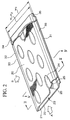
- FIG. 1 is a front view showing a heat exchanger 10, which is designed in accordance with the first embodiment of the invention.
- the heat exchanger 10 is constructed by tubes 11 each having a flat shape, a pair of head pipes 12, 13 and corrugated fins 14.
- the head pipes 12, 13 are arranged in contact with both ends of the tubes 11, wherein they communicate with refrigerant passages inside of the tubes 11 respectively.
- Each of the corrugated fins 14 is arranged between the tubes 11, wherein crest portions are brought into contact with the tubes 11.
- An inside space of the head pipe 12 is partitioned into two sections (hereinafter, referred to as an upper section and a lower section) by a partition plate 15, which is arranged slightly below a center level of the head pipe 12.
- a refrigerant inlet pipe 16 is installed to communicate with the upper section of the head pipe 12, while a refrigerant outlet pipe 17 is installed to communicate with the lower section of the head pipe 12.
- An overall front area of the heat exchanger 10 is divided into two areas (i.e., an upper area "a” and a lower area "b") by the partition plate 15.
- Refrigerant is introduced to flow in the tubes 11 in different directions (A) in connection with the two areas.
- refrigerant flow in a direction from the head pipe 12 to the head pipe 13.
- refrigerant flow in another direction from the head pipe 13 to the head pipe 12.
- Each of the tubes 11 is constructed as shown in FIG. 2. That is, the tube 11 is made by bending a flat plate 20 to form a first wall 21 and a second wall 22, which are arranged opposite to each other and in parallel with each other. So, a refrigerant passage 23 is formed in a space being encompassed by the walls 21, 22.
- a number of dimples 24 are formed on exterior surfaces of the tube 11 and are made by applying external pressures to the walls 21, 22 to cave in at selected positions. Because of formation of the dimples 24, a number of swelling portions 25 are correspondingly formed to swell from interior surfaces of the tube 11 within the refrigerant passage 23.
- a top portion 25a of the swelling portion 25 has an elliptical shape in plan view being defined by a short length (or short diameter) and a long length (or a long diameter), which is placed along a length direction (i.e., "A" in FIG. 2) of the tube 11.
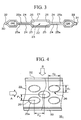
- their top portions 25a are brought into contact with each other as shown in FIG. 3. That is, the two swelling portions 25 whose top portions 25a are brought into contact with each other are connected together to form a column 26 which is provided between the first and second walls 21, 22 and whose section has an elliptical shape.
- the sectional shape of the column 26 is not necessarily limited to the elliptical shape, so it can be formed like an elongated circular shape, for example.
- the column 26 is not necessarily made in a hollow shape, so it is possible to make the column 26 solid.
- the swelling portions 25 are arranged to adjoin with each other as shown in FIG. 4.
- adjacent swelling portions which are arranged adjacent to each other obliquely with respect to the direction A, are arranged in a zigzag manner while being partially overlapped with each other in view of a direction perpendicular to the direction A. Therefore, the columns 26 are correspondingly arranged in a zigzag manner in conformity with the swelling portions 25.
- an air inlet direction by which air is introduced to perform heat exchange coincides with a width direction B of the tube 11.
- the tube 11 has a front-end portion 30 and a back-end portion 31, which are arranged apart from each other in the air inlet direction.
- splitter plates 32, 33 are formed together with the front-end portion 30 and the back-end portion 31 respectively.
- Each of the splitter plates 32, 33 is formed in prescribed thickness which is relatively thin to act as a flow straightener for straightening an inlet air flow around the tube 11.
- both ends of the tube 11 are inserted into the head pipes 12, 13 respectively.
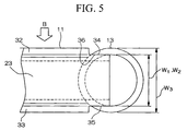
- FIG. 5 shows that one end of the tube 11 is inserted into the head pipe 13.
- cut sections 34, 35 are formed by partly cutting out the splitter plates 32, 33 of the tube 11. That is, each end of the tube 11 has a prescribed end shape, by which it is inserted into the head pipe (12 or 13).
- a number of tube insertion holes 36 are formed at selected positions on surfaces of the head pipes 12, 13. Each tube insertion hole 36 coincides with the end shape of the tube 11 to enable insertion of the tube 11 therein.
- channels 37 are formed at both ends of the tube insertion hole 36 to allow cut ends of the splitter plates 32, 33 of the tube 11 being inserted therein.
- the tube insertion hole 36 has an elongated shape whose width w1 substantially coincides with width w2 of the end portion of the tube 11 in which the cut sections 34, 35 are formed.
- an overall width w3 of the tube 11 including the splitter plates 32, 33 is made larger than the width w1 of the tube insertion hole 36.
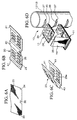
- a flat plate (or sheet metal) 20 shown in FIG. 6A is prepared for manufacture of the tube 11. Brazing material is clad on the surfaces of the flat plate 20, which are made as an interior surface and an exterior surface of the tube 11 being manufactured. In addition, prescribed sections are cut from selected end portions of the flat plate 20 in advance, wherein they are designated as the cut sections 34, 35.
- the flat plate 20 is subjected to press working or roll working to form swelling portions 25 in connection with a refrigerant passage 23 as shown in FIG. 6B.
- a bending overlap width 40 is formed in connection with a front-end portion 30, while brazing tabs 41 are formed in connection with a back-end portion 31.
- the flat plate 20 is bent along with a center line of the bending overlap width 40, which is shown in FIG. 6C.
- the bending overlap width 40 is folded so that two parts thereof come in connection with each other, while the brazing portions 41 are approaching each other and are then brought in contact with each other. Further, top portions 25a of the swelling portions 25 are brought in contact with each other.
- a head pipe 12 (or 13) having tube insertion holes 36 as shown in FIG. 6D.
- an end portion of the tube 11 is inserted into the tube insertion hole 36 of the head pipe 12 (or 13).
- a corrugated fin 14 is arranged between adjacent tubes 11 in elevation, so that a heat exchanger 20 is being assembled.
- the assembled heat exchanger 10 is put into a heating furnace (not shown), wherein it is heated for a certain time with a prescribed temperature. So, the brazing material clad on the surfaces of the flat plate 20 (i.e., tube 11) is melted, so that parts of the heat exchanger 10 are subjected to brazing.
- brazing is performed on two parts of the bending overlap width 40, the brazing portions 41 and the top portions 25a of the swelling portions 25, all of which are respectively bonded together.
- brazing is performed between the end portion of the tube 11 and the tube insertion hole 36, which are bonded together.
- brazing is performed to actualize bonding between the tube 11 and crest portions of the corrugated fin 14, which are brought in contact with each other when the corrugated fin 14 is arranged in connection with the tube 11.
- each of columns 26 which are arranged inside of the refrigerant passage 23 has a prescribed sectional shape corresponding to an elliptical shape whose long length matches with the direction A.
- a refrigerant flow may firstly collide with a front-end portion of the column 26 in which curvature becomes small along side surfaces.
- refrigerant flow is accelerated in flow velocity to progress from the front-end portion of the column 26 along its side surfaces. So, it is possible to improve a local heat transfer rate. Then, the refrigerant flow passes by the front-end portion to reach a back-end portion of the column 26.
- curvature becomes large along the side surfaces with respect to the back-end portion of the column 26. This hardly causes flow separation in which an eddy flow is separated from a main flow in the refrigerant flow. That is, it is possible to suppress shape resistance of the column 26 being small, so it is possible to reduce flow resistance.
- column bodies whose sectional shapes correspond to a circular shape and an elliptical shape respectively and which are arranged in flow fields.
- the column body having the elliptical shape in section is arranged in the flow field in such a way that a long length matches with a flow direction.
- a surface flow length along a side surface of the column body is given by a mathematical expression of s d 2 where "s” denotes a length from a stagnation point at a tip end of the column body along the side surface, while a surface local heat transfer rate is given by a mathematical expression of Nu Re 1 ⁇ 2 where "Nu” denotes Nusselt number, and "Re” denotes Reynolds number.
- FIG. 7 shows a result of the comparison between the aforementioned column bodies with respect to a relationship between the surface flow length and surface local heat transfer rate.
- FIG. 8 shows a result of comparison between the column bodies with respect to a relationship between the Reynolds number Re and a drag coefficient C D representative of flow resistance.
- the column body having the elliptical section is referred to as an "elliptical" column body, while the column body having the circular section is referred to as a "circular" column body.
- the surface local heat transfer rate of the elliptical column body at its front-end portion (which is close to the stagnation point) has a remarkably high value as compared with the circular column body.
- the surface local heat transfer rate of the elliptical column body is reduced as a flow passes by the front-end portion to reach a back-end portion, but it is normally higher than the surface local heat transfer rate of the circular column body.
- FIG. 8 shows that the drag coefficient of the elliptical column body is normally lower than the drag coefficient of the circular column body, regardless of variations of the Reynolds number Re. Roughly speaking, the drag coefficient of the elliptical column body is approximately a half of the drag coefficient of the circular column body.
- the elliptical sectional shape of the column 26 meets a relationship of an inequality (1), as follows: 2.0 ⁇ d 2 d 1 ⁇ 3.0 where "d1" denotes a short length, and “d2" denotes a long length shown in FIG. 4.
- the heat exchanger 10 is designed such that the columns 26 are arranged inside of the refrigerant passage 23 in a zigzag manner.
- FIG. 9 shows a relationship between refrigerant circulation and heat transfer rate
- FIG. 10 shows a relationship between refrigerant circulation and pressure loss.
- Those graphs show that both of the tube 11 having the columns and the extrusion tube are similarly increased in pressure loss in response to increase of the refrigerant circulation.
- the tube 11 is capable of remarkably increasing the heat transfer rate in response to the increase of the refrigerant circulation.
- a reference symbol “p1” designates a center distance (or pitch) between two columns which are arranged obliquely adjacent to each other in a direction B (corresponding to a width direction of the tube).
- a reference symbol “p2” designates a center distance between the two columns which are arranged obliquely adjacent to each other in a direction A.
- the center distances p1, p2 should be respectively related to a short length d1 and a long length d2 of the column by prescribed relationships, which are expressed by inequalities (2), (3), as follows: 1.5 ⁇ p 1 d 1 ⁇ 3.0 0.5 ⁇ p 2 d 2 ⁇ 1.5 That is, it is preferable that the columns are arranged in a zigzag manner to meet the aforementioned relationships.
- the inequality (2) is determined by the following reasons:
- a value of p1/d1 becomes lower than 1.5, an interval of distance between obliquely adjacent columns in the direction B is narrowed to increase flow resistance in the refrigerant passage 23. If the value of p1/d1 becomes larger than 3.0, the interval of distance between the obliquely adjacent columns are broadened to decrease the flow resistance in the refrigerant passage 23, while flow speed of the refrigerant flowing between the columns is reduced to decrease the heat transfer rate.
- the inequality (3) is determined by the following reasons:
- a value of p2/d2 becomes lower than 0.5, an interval of distance between obliquely adjacent columns in the direction A is narrowed so that branch flows of refrigerant around the columns interfere with each other. This decreases the flow resistance and correspondingly reduces the heat transfer rate. If the value of p2/d2 becomes larger than 1.5, the interval of distance between the obliquely adjacent columns in the direction A is broadened so that branch flows of refrigerant at back sides of the columns are reduced. This reduces the heat transfer rate as well.
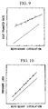
- FIG. 12 shows relationships between refrigerant circulation and heat transfer rate
- FIG. 13 shows relationships between refrigerant circulation and pressure loss.
- FIG. 12 shows that substantially same values are measured with respect to the heat transfer rate against the refrigerant circulation in the tube A(where p1/d1 ⁇ 1.5, p2/d2 ⁇ 0.6), tube B (where p1/d1 ⁇ 1.5, p2/d2 ⁇ 1.15) and tube C (where p1/d1 ⁇ 2.0, p2/d2 ⁇ 1.15).
- the tube D shows normally higher values with respect to the heat transfer rate against the refrigerant circulation.
- FIG. 13 shows that substantially same values are measured with respect to the pressure loss against the refrigerant circulation in the tubes A, B and C.
- the tube D shows slightly higher values with respect to the pressure loss against the refrigerant circulation, wherein small differences of the heat transfer rate emerge between the tube D and the other tubes (A, B, C).
- all the columns 26 are arranged to be separated from each other, wherein obliquely adjacent columns are arranged being partly overlapped with each other in the direction A.
- Such arrangement of the columns provides improvements in heat transfer rate and pressure-proof strength with respect to the tube 11 as a whole.
- the surface local heat transfer rate measured along the side surface of the column is made highest at the front-end portion and becomes lower in a direction toward the back-end portion.
- Consideration is made with respect to two obliquely adjacent columns which are obliquely arranged in the direction A, namely, an upstream column and a downstream column which are arranged at different locations along the refrigerant flow.
- the upstream column and downstream column are arranged being partly overlapped with each other in the direction A. That is, a front-end portion of the downstream column is located in an upstream side rather than a back-end portion of the upstream column. In that case, the front-end portion of the downstream column compensates for reduction of the surface local heat transfer rate at the back-end portion of the upstream column. Thus, it is possible to improve the overall heat transfer rate of the tube 11 on the average.
- each column is made by bonding the top portions (25a) of the swelling portions (25) respectively formed on the first and second walls 21, 22 by brazing. In other words, each column acts as a joint formed between the first and second walls 21, 22. Because the columns are arranged regularly in the direction A, it is possible to secure broad joint portions between the top portions (25a) of the swelling portions (25).
- any section of the tube 11 taken in the direction A contains adhesion between the swelling portions 25 of the first and second walls 21, 22.
- each of the swelling portions 42 is arranged in such a manner that the long length thereof is arranged with inclination to a horizontal line corresponding to the direction A by a prescribed angle ⁇ .
- each pair of the swelling portions 42 are arranged to conform with each other in elevation such that their top portions 42 are brought into contact with each other.
- a column 43 is made by jointing together the pair of the swelling portions 42 inside of the tube 11.
- the swelling portions 42 are arranged in a zigzag manner with respect to the direction A. That is, obliquely adjacent swelling portions which are arranged obliquely adjacent to each other in the direction A are arranged independently from each other but are partly overlapped with each other along the direction A. Thus, columns 43 are arranged correspondingly in conformity with the swelling portions 42.
- the heat exchanger of the second embodiment is designed such that obliquely adjacent columns 43 are arranged being partly overlapped with each other along the direction A in the tube 11. So, it is possible to provide improvements in heat transfer rate and pressure-proof strength of the tube 11.
- the second embodiment is characterized by that each of the swelling portions 42 constructing the columns 43 is arranged in a slanted manner in which its long length is arranged with inclination to the direction A by the angle ⁇ .
- a front-end portion of the downstream column is located slightly different from a back-end portion of the upstream column by a prescribed offset in a direction B (which is perpendicular to the direction A, not shown in FIG. 14). For this reason, the front-end portion of the downstream column does not act as a "shadow zone" for the refrigerant flow. This increases an amount of refrigerant that collide with each of front-end portions of the columns 43. Thus, it is possible to improve the heat transfer rate with respect to the tube 11 as a whole.
- the inclination angle ⁇ within a range of ⁇ 7° .
- Such a range is determined by the following reasons:
- the heat transfer rate is correspondingly improved so that the second embodiment is able to demonstrate remarkable effects in heat-exchange property.
- the inclination angle becomes larger or lower than the range of ⁇ 7° , flow separation is easily caused to occur in the refrigerant flow, so that the heat transfer rate is reduced.
- the third embodiment is basically designed such that the tube 11 is constructed by first and second walls 21, 22 between which columns 26 are formed by swelling portions 25 and are arranged obliquely adjacent to each other.
- the third embodiment is characterized by that side walls 44 are formed and arranged integrally with side-end portions of the first and second walls 21, 22. Therefore, a refrigerant passage 23 is formed and encompassed by those walls 21, 22, 44.
- semi-columns 46 each having a prescribed shape corresponding to a semi-shape of the aforementioned column 26 whose sectional shape corresponds to an ellipse are arranged on the side walls 44.
- Each of the semi-columns 46 is formed by a pair of semi-swelling portions 45 whose top portions are brought into contact with each other.
- the semi-swelling portions 45 are formed by applying external pressures to exterior surfaces of the first and second walls 21, 22 to partially cave in at selected positions.
- Each of the semi-columns 46 whose sectional shapes correspond to semi-ellipses is arranged in connection with the columns 26 whose sectional shapes correspond to ellipses and which are arranged in a zigzag manner. That is, one semi-column 46 is arranged on the side wall 44 at a prescribed location, which approximately corresponds to a center position between two columns (each designated by a reference numeral "26a") being arranged adjacent to each other along a direction A within the columns 26. In addition, the semi-column 46 is also arranged adjacent to a column 26b, which is arranged obliquely adjacent to the column 26a, along a direction B.
- the columns 26 whose sectional shapes correspond to ellipses are arranged in a zigzag manner along the direction A in the tube 11, wherein one or two columns 26 are arranged in each section taken along the direction B.
- there are two kinds of sections each taken along the direction B namely, a first section in which two columns 26a are arranged and a second section in which one column 26b is arranged. Those sections are arranged alternately along the direction A in the tube 11.
- the second section having the column 26b is reduced in joint strength because of a small total joint area formed between the first and second walls 21, 22 which are jointed together by the column 26b.
- the second section having the column 26b is reduced in pressure-proof strength as compared with the first section having the two columns 26a.
- the semi-columns 46 each having a semi-shape of the column 26 are arranged in connection with the second section having the column 26b so as to increase a total joint area between the first and second walls 21, 22 which are jointed together by the column 26b and two semi-columns 46 with respect to the second section. Therefore, it is possible to increase the joint strength with respect to the second section. In other words, it is possible to increase the pressure-proof strength of the second section being substantially equivalent to the pressure-proof strength of the first section having the two columns 26a.
- FIG. 16 shows a modified example of the heat exchanger of the third embodiment, which is designed as a laminated heat exchanger used for an evaporator.
- the heat exchange of FIG. 16 has a refrigerant passage unit 47 equipped with a U-shaped refrigerant passage 50 having a refrigerant inlet 48 and a refrigerant outlet 49 at upper ends. That is, refrigerant is introduced into the refrigerant inlet 48 to flow inside of the U-shaped refrigerant passage 50, wherein it firstly flows down to a lower end and then flows upwardly toward the refrigerant outlet 49.
- the U-shaped refrigerant passage 50 is not formed in a straight shape like the foregoing refrigerant passage 23 but is basically designed to have columns as similar to the refrigerant passage 23 inside of the tube 11 shown in FIG. 15. That is, semi-columns are arranged along side walls of the refrigerant passage 50. Thus, it is possible to improve pressure-proof strength and heat transfer rate with respect to the refrigerant passage unit 47.
- the heat exchanger of the fourth embodiment is designed as a condenser that condenses refrigerant by radiating heat to the external air.
- the present heat exchanger uses the tube 11 shown in FIG. 17, which is characterized by that each of swelling portions 25 is gradually enlarged in size along a direction A while maintaining figure similarity in sectional shape.
- relatively small swelling portions are formed and arranged in an upstream side, while relatively large swelling portions are formed and arranged in a downstream side.
- densities (or occupied areas) of the swelling portions in the upsteam side are relatively small, while the swelling portions are closely and tightly arranged with each other in the downstream side. Therefore, columns 26 are correspondingly formed and arranged in coformity with the swelling portions 25.
- sectional areas of a refrigerant passage 23 taken along lines perpendicular to the direction A become small in the direction A from the upstream side to the downstream side of the tube 11.
- the heat exchanger that is designed as the condenser
- dryness is reduced in response to progress of refrigerant that flow from the upstream side to the downstream side, in other words, a liquid phase is increased as compared with a gas phase in response to the progress of the refrigerant.
- pressures which are imparted to interior wall surfaces of the tube 11 by refrigerant are gradually reduced along the direction A.
- the tube 11 used by the heat exchanger of the fourth embodiment is designed such that sectional areas of the refrigerant passage 23 are gradually reduced in response to the reduction of the pressures. So, it is possible to provide substantially constant pressures being imparted to the interior wall surfaces of the tube 11.
- the tube 11 of the fourth embodiment is characterized by that the columns 26 are made being gradually enlarged in sizes while maintaining a certain figure similarity in the direction A directing from the upstream side to the downstream side. So, the sectional areas of the refrigerant passage 23 taken along lines perpendicular to the direction A are made being gradually reduced in the direction A from the upstream side to the downstream side.
- the fourth embodiment can be modified such that the columns 26 are changed in size as well as shape without maintaining figure similarity. Or, it can be modified such that the columns 26 are not changed in sizes but are changed in arrangement (or density) in the direction A.
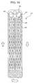
- the heat exchanger of the fifth embodiment is designed as an evaporator that absorbs heat from the external air to gasify refrigerant.
- the present heat exchanger is constructed by laminating refrigerant passage units 53, each of which is formed by overlapping together flat plates 51, 52 each roughly having a rectangular shape as shown in FIG. 18.
- the flat plates 51, 52 are assembled together by jointing their peripheral portions and center portions together.
- a U-shaped refrigerant passage 56 which is shaped like a flat tube is formed in the refrigerant passage unit 53 having a refrigerant inlet 54 and a refrigerant outlet 55 at upper ends.
- refrigerant is introduced into the refrigerant inlet 54 to flow inside of the U-shaped refrigerant passage 56, wherein it flows down to a lower end and then flows upwardly toward to the refrigerant outlet 55.
- a partition portion 57 is formed to partition the refrigerant passage 56 into two sections (i.e., a right section and a left section in FIG. 18).
- the partition portion 57 is formed in a slanted manner. That is, a lower end 57b of the partition portion 57 is arranged substantially at a center with an equal distance being measured from both ends of the flat plates 51, 52, while an upper end 57a of the partition portion 57 is arranged close to the refrigerant inlet 54 rather than the refrigerant outlet 55.
- sectional areas of the refrigerant passage 56 taken along lines perpendicular to a flow direction of refrigerant are made small in upstream areas but are made large in downstream areas. That is, the sectional shapes of the refrigerant passage 56 are gradually increased along refrigerant flow from an upstream side to a downstream side.
- the columns 59 are uniformly arranged to maintain constant distances in a refrigerant flow direction and its perpendicular direction. That is, a constant distance is maintained between adjacent columns 59 in the refrigerant flow direction. In addition, a constant distance is also maintained between adjacent columns 59 in a direction perpendicular to the refrigerant flow direction. Due to such uniform arrangement of the columns 59 and a slanted arrangement of the partition portion 57, it is possible to make sectional areas of the refrigerant passage 56, taken along lines perpendicular to the refrigerant flow direction, being larger in a direction from the upstream side to the downstream side.
- the heat exchanger which is designed as the evaporator
- dryness is increased in response to progress of refrigerant that flow from the upstream side to the downstream side, in other words, gas phase is increased as compared with liquid phase in response to the progress of the refrigerant.
- pressures imparted to interior wall surfaces of the refrigerant passage 56 are gradually increased in the refrigerant passage unit 53.
- the heat exchanger of the fifth embodiment using the refrigerant passage unit 53 is designed such that the sectional areas of the refrigerant passage 56 are made gradually larger in response to the increases of the pressures.
- the columns 59 are uniformly arranged in the refrigerant passage 56 such that a constant distance is maintained between the adjacent columns, so that the sectional areas of the refrigerant passage 56 are gradually increased in the refrigerant flow direction from the upstream side to the downstream side.
- the fifth embodiment can be modified such that the columns 59 are subjected to uniform arrangement but are gradually enlarged in size along the refrigerant flow direction toward the downstream side.
- it can be modified such that the columns 59 are not changed in size but are gradually increased in number along the refrigerant flow direction toward the downstream side, in other words, densities of the columns 59 are gradually increased along the refrigerant flow direction toward the downstream side.
Landscapes
- Engineering & Computer Science (AREA)
- Physics & Mathematics (AREA)
- Thermal Sciences (AREA)
- Mechanical Engineering (AREA)
- General Engineering & Computer Science (AREA)
- Heat-Exchange Devices With Radiators And Conduit Assemblies (AREA)
Applications Claiming Priority (2)
| Application Number | Priority Date | Filing Date | Title |
|---|---|---|---|
| JP15302299A JP4175443B2 (ja) | 1999-05-31 | 1999-05-31 | 熱交換器 |
| JP15302299 | 1999-05-31 |
Publications (2)
| Publication Number | Publication Date |
|---|---|
| EP1058079A2 true EP1058079A2 (fr) | 2000-12-06 |
| EP1058079A3 EP1058079A3 (fr) | 2001-04-11 |
Family
ID=15553259
Family Applications (1)
| Application Number | Title | Priority Date | Filing Date |
|---|---|---|---|
| EP00111265A Withdrawn EP1058079A3 (fr) | 1999-05-31 | 2000-05-25 | Echangeur de chaleur et sa méthode de fabrication |
Country Status (8)
| Country | Link |
|---|---|
| US (2) | US6453989B1 (fr) |
| EP (1) | EP1058079A3 (fr) |
| JP (1) | JP4175443B2 (fr) |
| KR (1) | KR100365639B1 (fr) |
| CN (1) | CN1205452C (fr) |
| AU (1) | AU739859B2 (fr) |
| CA (1) | CA2309240A1 (fr) |
| TW (1) | TW535893U (fr) |
Cited By (6)
| Publication number | Priority date | Publication date | Assignee | Title |
|---|---|---|---|---|
| DE102004041308A1 (de) * | 2004-08-25 | 2006-03-02 | Behr Gmbh & Co. Kg | Kühler |
| EP1644683A4 (fr) * | 2003-05-29 | 2010-07-21 | Halla Climate Control Corp | Plaque pour changeur de chaleur |
| EP2472207A1 (fr) * | 2002-01-10 | 2012-07-04 | Mitsubishi Heavy Industries, Ltd. | Évaporateur de type à empilement de plaques |
| WO2014009537A1 (fr) * | 2012-07-13 | 2014-01-16 | Delphi Automotive Systems Luxembourg Sa | Refroidisseur d'air de suralimentation |
| CN105157458A (zh) * | 2015-10-23 | 2015-12-16 | 广州市雷子克电气机械有限公司 | 气气换热器 |
| DE102019201387A1 (de) * | 2019-02-04 | 2020-08-06 | Mahle International Gmbh | Stapelscheibe für einen Stapelscheibenwärmeübertrager und zugehöriger Stapelscheibenwärmeübertrager |
Families Citing this family (56)
| Publication number | Priority date | Publication date | Assignee | Title |
|---|---|---|---|---|
| US6729388B2 (en) * | 2000-01-28 | 2004-05-04 | Behr Gmbh & Co. | Charge air cooler, especially for motor vehicles |
| JP2002130985A (ja) * | 2000-10-18 | 2002-05-09 | Mitsubishi Heavy Ind Ltd | 熱交換器 |
| JP4605925B2 (ja) * | 2001-03-08 | 2011-01-05 | サンデン株式会社 | 積層型熱交換器 |
| US6595273B2 (en) * | 2001-08-08 | 2003-07-22 | Denso Corporation | Heat exchanger |
| KR100482825B1 (ko) * | 2002-07-09 | 2005-04-14 | 삼성전자주식회사 | 열교환기 |
| KR100482827B1 (ko) | 2002-09-14 | 2005-04-14 | 삼성전자주식회사 | 열교환기 |
| KR20050030490A (ko) * | 2003-09-26 | 2005-03-30 | 엘에스전선 주식회사 | 열교환기 |
| SE526129C2 (sv) * | 2003-11-26 | 2005-07-12 | Eco Lean Res & Dev As | Värmeväxlarplatta och en plattvärmeväxlare innefattande sådana plattor |
| US6945320B2 (en) * | 2004-01-26 | 2005-09-20 | Lennox Manufacturing Inc. | Tubular heat exchanger with offset interior dimples |
| US20050241605A1 (en) * | 2004-04-29 | 2005-11-03 | Bedwell Donald R | Fluid flow surface with indentations |
| US20050274489A1 (en) * | 2004-06-10 | 2005-12-15 | Brand Joseph H | Heat exchange device and method |
| JP2006183969A (ja) * | 2004-12-28 | 2006-07-13 | Mahle Filter Systems Japan Corp | 積層型オイルクーラの熱交換コア |
| EP1860330A4 (fr) * | 2005-03-04 | 2011-02-16 | Gennady Iraklievich Kiknadze | Procede de formation d'un courant de formation de jets tourbillonnants integres a un flux et surface conçue pour sa mise en oeuvre |
| US7264045B2 (en) * | 2005-08-23 | 2007-09-04 | Delphi Technologies, Inc. | Plate-type evaporator to suppress noise and maintain thermal performance |
| KR20070034435A (ko) * | 2005-09-23 | 2007-03-28 | 피어불그 게엠베하 | 열교환기 |
| US20100243225A1 (en) * | 2006-01-19 | 2010-09-30 | Werner Zobel | Flat tube, flat tube heat exchanger, and method of manufacturing same |
| JP2007212084A (ja) * | 2006-02-10 | 2007-08-23 | Denso Corp | 熱交換器 |
| JP4811087B2 (ja) * | 2006-03-31 | 2011-11-09 | 株式会社デンソー | 熱交換器 |
| US7476993B2 (en) * | 2006-04-28 | 2009-01-13 | Pratt & Whitney Canada Corp. | Method of making electric machine winding |
| DK1894660T3 (da) * | 2006-08-31 | 2012-01-16 | Aurubis Ag | Fremgangsmåde til fremstilling af et metalrør ved sammenvalsning af mindst to profiler til dannelse af mindst tre kanaler |
| ITVR20060154A1 (it) * | 2006-10-06 | 2008-04-07 | Gianfranco Natali | Procedimento per la realizzazione di tubi di scambiatori di calore e tubi di scambiatori di calore |
| US20090087604A1 (en) * | 2007-09-27 | 2009-04-02 | Graeme Stewart | Extruded tube for use in heat exchanger |
| US20090114373A1 (en) * | 2007-11-02 | 2009-05-07 | Calsonic Kansei Corporation | Heat exchanger |
| US8267163B2 (en) | 2008-03-17 | 2012-09-18 | Visteon Global Technologies, Inc. | Radiator tube dimple pattern |
| JP5563592B2 (ja) * | 2008-12-17 | 2014-07-30 | スウェップ インターナショナル アクティエボラーグ | ろう付けした熱交換器のポート開口部 |
| DE102008064090A1 (de) | 2008-12-19 | 2010-08-12 | Mahle International Gmbh | Abgaskühler |
| CN102292611A (zh) * | 2009-01-22 | 2011-12-21 | 大金工业株式会社 | 热交换器及具备该热交换器的热泵式热水供给机 |
| BRPI0900535A2 (pt) * | 2009-03-26 | 2010-12-14 | Refrex Evaporadores Do Brasil S A | trocador de calor |
| JP5517745B2 (ja) * | 2010-05-24 | 2014-06-11 | サンデン株式会社 | 熱交換器用チューブ及び熱交換器 |
| RU2502932C2 (ru) * | 2010-11-19 | 2013-12-27 | Данфосс А/С | Теплообменник |
| JP6100459B2 (ja) * | 2011-12-19 | 2017-03-22 | フタバ産業株式会社 | 燃料電池用熱交換器 |
| JP5544580B1 (ja) * | 2013-07-26 | 2014-07-09 | 株式会社 エコファクトリー | 空気調和装置及び空気調和装置の運転方法 |
| CN103743281B (zh) * | 2014-01-16 | 2015-10-28 | 深圳市丰瑞德机电技术有限公司 | 一种换热板、热交换器及热交换系统 |
| US10816277B2 (en) * | 2014-07-21 | 2020-10-27 | Hanon Systems | Heat exchanger tubes with fluid communication channels |
| GB2542995A (en) * | 2014-07-21 | 2017-04-05 | Dana Canada Corp | Heat exchanger with flow obstructions to reduce fluid dead zones |
| CN104101244B (zh) * | 2014-08-01 | 2016-06-08 | 兰州交通大学 | 椭圆管管翅式换热器流线型变波幅波纹翅片 |
| CN104110992B (zh) * | 2014-08-01 | 2016-06-08 | 兰州交通大学 | 椭圆管管翅式换热器流线型变波幅圆弧形波纹翅片 |
| US10222125B2 (en) * | 2015-04-06 | 2019-03-05 | International Business Machines Corporation | Burst resistant thin wall heat sink |
| JP6754663B2 (ja) * | 2016-10-14 | 2020-09-16 | リンナイ株式会社 | 熱交換器、及びそれを備えた燃焼装置 |
| CN106705713B (zh) * | 2016-12-09 | 2019-04-26 | 厦门大学 | 一种具有多流路互联结构的微通道换热器及其制造方法 |
| DE102018200809A1 (de) * | 2018-01-18 | 2019-07-18 | Mahle International Gmbh | Stapelscheibenwärmetauscher |
| CN110887396B (zh) * | 2018-09-10 | 2021-03-05 | 浙江盾安热工科技有限公司 | 换热器扁管及具有其的换热器 |
| CN111351376A (zh) * | 2018-12-21 | 2020-06-30 | 浙江盾安热工科技有限公司 | 换热器扁管及具有其的换热器 |
| CN111366013A (zh) * | 2018-12-26 | 2020-07-03 | 浙江盾安热工科技有限公司 | 扁管及换热器 |
| CN110108019A (zh) * | 2019-05-31 | 2019-08-09 | 胡志鹏 | 燃气锅炉 |
| CN110160379A (zh) * | 2019-05-31 | 2019-08-23 | 胡志鹏 | 热交热器芯体及燃气锅炉 |
| CN110388839A (zh) * | 2019-05-31 | 2019-10-29 | 胡志鹏 | 热交换器及燃气锅炉 |
| CN110108020A (zh) * | 2019-05-31 | 2019-08-09 | 胡志鹏 | 热交换器的换热单元及燃气锅炉 |
| CN112682500B (zh) * | 2020-12-31 | 2023-05-26 | 南宁市安和机械设备有限公司 | 一种采用错位打点油冷器管制成的油冷器 |
| CN112728963B (zh) * | 2020-12-31 | 2024-04-26 | 南宁市安和机械设备有限公司 | 一种采用错位打点管制成的水散热器 |
| CN112792508B (zh) * | 2021-01-04 | 2023-04-25 | 南宁市安和机械设备有限公司 | 一种水散热器的制作工艺 |
| CN112696334A (zh) * | 2021-01-04 | 2021-04-23 | 南宁市安和机械设备有限公司 | 一种错位打点管制成的空压机散热器 |
| CN112683085A (zh) * | 2021-01-11 | 2021-04-20 | 南宁市安和机械设备有限公司 | 一种采用错位打点管制成的工程水散热器 |
| CN113669773B (zh) * | 2021-08-31 | 2022-09-20 | 临沂盛荣热电有限公司 | 一种热力管网换热系统 |
| KR20240089107A (ko) * | 2021-10-01 | 2024-06-20 | 에밥코 인코포레이티드 | 직접 열교환 충진재 |
| CN118705914B (zh) * | 2024-07-12 | 2026-04-21 | 西安交通大学 | 一种采用混合翅片的印刷电路板换热器芯体 |
Citations (1)
| Publication number | Priority date | Publication date | Assignee | Title |
|---|---|---|---|---|
| JPH11153022A (ja) | 1997-11-21 | 1999-06-08 | Nissan Motor Co Ltd | ディーゼルエンジンの燃料制御装置 |
Family Cites Families (18)
| Publication number | Priority date | Publication date | Assignee | Title |
|---|---|---|---|---|
| US4600053A (en) * | 1984-11-23 | 1986-07-15 | Ford Motor Company | Heat exchanger structure |
| JPS6334489A (ja) * | 1986-07-28 | 1988-02-15 | Nippon Denso Co Ltd | 熱交換器 |
| JPH0228981A (ja) | 1988-07-19 | 1990-01-31 | Mitsubishi Heavy Ind Ltd | 波長可変レーザーの周波数安定装置 |
| KR940010978B1 (ko) * | 1988-08-12 | 1994-11-21 | 갈소니꾸 가부시끼가이샤 | 멀티플로우형의 열교환기 |
| JP2968807B2 (ja) | 1989-11-14 | 1999-11-02 | カルソニック株式会社 | 熱交換器用伝熱管及びその製造方法 |
| US5186250A (en) * | 1990-05-11 | 1993-02-16 | Showa Aluminum Kabushiki Kaisha | Tube for heat exchangers and a method for manufacturing the tube |
| US5101891A (en) * | 1991-06-03 | 1992-04-07 | General Motors Corporation | Heat exchanger tubing with improved fluid flow distribution |
| US5172476A (en) * | 1991-08-14 | 1992-12-22 | General Motors Corporation | Method of manufacturing heat exchanger tubing |
| US5409056A (en) * | 1992-05-11 | 1995-04-25 | General Motors Corporation | U-flow tubing for evaporators with bump arrangement for optimized forced convection heat exchange |
| EP0632245B1 (fr) * | 1993-07-01 | 1997-10-15 | THERMAL-WERKE Wärme-, Kälte-, Klimatechnik GmbH | Echangeur de chaleur eau-air en aluminium pour véhicules automobiles |
| DE69413173T2 (de) * | 1993-10-22 | 1999-06-02 | Zexel Corp | Rohrelement für einen Laminatwärmetauscher |
| JP3155422B2 (ja) | 1994-06-24 | 2001-04-09 | 修一 藤森 | 包装材および包装寿司 |
| KR100217515B1 (ko) * | 1994-09-30 | 1999-09-01 | 오타 유다카 | 적층형 열교환기의 열교환용 도관 및 그 제조방법 |
| DE19518657A1 (de) * | 1995-04-26 | 1996-10-31 | Lingemann Helmut Gmbh & Co | Mehrkammerflachrohr für Wärmetauscher sowie Verfahren zu seiner Herstellung |
| JP3346951B2 (ja) * | 1995-06-02 | 2002-11-18 | カルソニックカンセイ株式会社 | 熱交換器用チューブ |
| JPH0942882A (ja) * | 1995-07-24 | 1997-02-14 | Sanden Corp | チューブエレメント及びそれを用いた積層型熱交換器 |
| JPH1019494A (ja) * | 1996-07-05 | 1998-01-23 | Zexel Corp | 熱交換器用偏平チューブ |
| JP4122578B2 (ja) * | 1997-07-17 | 2008-07-23 | 株式会社デンソー | 熱交換器 |
-
1999
- 1999-05-31 JP JP15302299A patent/JP4175443B2/ja not_active Expired - Fee Related
-
2000
- 2000-05-22 KR KR1020000027445A patent/KR100365639B1/ko not_active Expired - Fee Related
- 2000-05-23 TW TW091212610U patent/TW535893U/zh not_active IP Right Cessation
- 2000-05-24 CN CNB001176153A patent/CN1205452C/zh not_active Expired - Fee Related
- 2000-05-24 CA CA002309240A patent/CA2309240A1/fr not_active Abandoned
- 2000-05-25 EP EP00111265A patent/EP1058079A3/fr not_active Withdrawn
- 2000-05-26 US US09/579,272 patent/US6453989B1/en not_active Expired - Lifetime
- 2000-05-26 AU AU36454/00A patent/AU739859B2/en not_active Ceased
-
2002
- 2002-08-01 US US10/208,848 patent/US20030019618A1/en not_active Abandoned
Patent Citations (1)
| Publication number | Priority date | Publication date | Assignee | Title |
|---|---|---|---|---|
| JPH11153022A (ja) | 1997-11-21 | 1999-06-08 | Nissan Motor Co Ltd | ディーゼルエンジンの燃料制御装置 |
Cited By (8)
| Publication number | Priority date | Publication date | Assignee | Title |
|---|---|---|---|---|
| EP2472207A1 (fr) * | 2002-01-10 | 2012-07-04 | Mitsubishi Heavy Industries, Ltd. | Évaporateur de type à empilement de plaques |
| EP1327845B1 (fr) * | 2002-01-10 | 2016-03-23 | Mitsubishi Heavy Industries, Ltd. | Echangeur de chaleur à plaques empilées |
| EP1644683A4 (fr) * | 2003-05-29 | 2010-07-21 | Halla Climate Control Corp | Plaque pour changeur de chaleur |
| US7934541B2 (en) | 2003-05-29 | 2011-05-03 | Halla Climate Control Corporation | Plate for heat exchanger |
| DE102004041308A1 (de) * | 2004-08-25 | 2006-03-02 | Behr Gmbh & Co. Kg | Kühler |
| WO2014009537A1 (fr) * | 2012-07-13 | 2014-01-16 | Delphi Automotive Systems Luxembourg Sa | Refroidisseur d'air de suralimentation |
| CN105157458A (zh) * | 2015-10-23 | 2015-12-16 | 广州市雷子克电气机械有限公司 | 气气换热器 |
| DE102019201387A1 (de) * | 2019-02-04 | 2020-08-06 | Mahle International Gmbh | Stapelscheibe für einen Stapelscheibenwärmeübertrager und zugehöriger Stapelscheibenwärmeübertrager |
Also Published As
| Publication number | Publication date |
|---|---|
| CA2309240A1 (fr) | 2000-11-30 |
| AU739859B2 (en) | 2001-10-25 |
| US6453989B1 (en) | 2002-09-24 |
| CN1275708A (zh) | 2000-12-06 |
| CN1205452C (zh) | 2005-06-08 |
| US20030019618A1 (en) | 2003-01-30 |
| AU3645400A (en) | 2000-12-21 |
| KR20000077371A (ko) | 2000-12-26 |
| JP2000346582A (ja) | 2000-12-15 |
| KR100365639B1 (ko) | 2002-12-26 |
| EP1058079A3 (fr) | 2001-04-11 |
| TW535893U (en) | 2003-06-01 |
| JP4175443B2 (ja) | 2008-11-05 |
Similar Documents
| Publication | Publication Date | Title |
|---|---|---|
| US6453989B1 (en) | Heat exchanger | |
| US6073688A (en) | Flat tubes for heat exchanger | |
| US5918664A (en) | Refrigerant evaporator constructed by a plurality of tubes | |
| US7117936B2 (en) | Tube for heat exchanger | |
| JP3445905B2 (ja) | 熱交換器およびそれに用いられるヘッダパイプの製造方法 | |
| US5441105A (en) | Folded parallel flow condenser tube | |
| US5318112A (en) | Finned-duct heat exchanger | |
| US6357520B1 (en) | Heat exchanger | |
| US20030029608A1 (en) | Heat exchanger | |
| JPH10318695A (ja) | 熱交換器 | |
| JP2001041675A (ja) | 熱交換器用チューブおよび熱交換器 | |
| CN103608639B (zh) | 翅片管型热交换器 | |
| CN107806777A (zh) | 无翅片换热器 | |
| US20010045277A1 (en) | Flat tubes for use with heat exchanger and manufacturing method thereof | |
| JPH0571884A (ja) | コア深さの小さい熱交換器 | |
| EP4425082B1 (fr) | Échangeur de chaleur à microcanaux | |
| US5934365A (en) | Heat exchanger | |
| JPS6039959B2 (ja) | 熱交換器 | |
| JP2528121B2 (ja) | 熱交換器 | |
| JP2984480B2 (ja) | 積層型熱交換器 | |
| EP0183211A2 (fr) | Modules d'échange de chaleur et méthode pour leur fabrication | |
| US5476140A (en) | Alternately staggered louvered heat exchanger fin | |
| WO1997014927A1 (fr) | Echangeur de chaleur | |
| US6575232B1 (en) | Heat exchanger | |
| JP2000105093A (ja) | 熱交換器 |
Legal Events
| Date | Code | Title | Description |
|---|---|---|---|
| PUAI | Public reference made under article 153(3) epc to a published international application that has entered the european phase |
Free format text: ORIGINAL CODE: 0009012 |
|
| 17P | Request for examination filed |
Effective date: 20000621 |
|
| AK | Designated contracting states |
Kind code of ref document: A2 Designated state(s): BE DE FR GB IT NL |
|
| AX | Request for extension of the european patent |
Free format text: AL;LT;LV;MK;RO;SI |
|
| PUAL | Search report despatched |
Free format text: ORIGINAL CODE: 0009013 |
|
| AK | Designated contracting states |
Kind code of ref document: A3 Designated state(s): AT BE CH CY DE DK ES FI FR GB GR IE IT LI LU MC NL PT SE |
|
| AX | Request for extension of the european patent |
Free format text: AL;LT;LV;MK;RO;SI |
|
| AKX | Designation fees paid |
Free format text: BE DE FR GB IT NL |
|
| 17Q | First examination report despatched |
Effective date: 20031120 |
|
| STAA | Information on the status of an ep patent application or granted ep patent |
Free format text: STATUS: THE APPLICATION IS DEEMED TO BE WITHDRAWN |
|
| 18D | Application deemed to be withdrawn |
Effective date: 20160218 |