EP1058461A2 - Farbbildprojektor - Google Patents
Farbbildprojektor Download PDFInfo
- Publication number
- EP1058461A2 EP1058461A2 EP00111707A EP00111707A EP1058461A2 EP 1058461 A2 EP1058461 A2 EP 1058461A2 EP 00111707 A EP00111707 A EP 00111707A EP 00111707 A EP00111707 A EP 00111707A EP 1058461 A2 EP1058461 A2 EP 1058461A2
- Authority
- EP
- European Patent Office
- Prior art keywords
- display devices
- lights
- light
- color projector
- lens unit
- Prior art date
- Legal status (The legal status is an assumption and is not a legal conclusion. Google has not performed a legal analysis and makes no representation as to the accuracy of the status listed.)
- Granted
Links
Images





Classifications
-
- H—ELECTRICITY
- H04—ELECTRIC COMMUNICATION TECHNIQUE
- H04N—PICTORIAL COMMUNICATION, e.g. TELEVISION
- H04N9/00—Details of colour television systems
- H04N9/12—Picture reproducers
- H04N9/31—Projection devices for colour picture display, e.g. using electronic spatial light modulators [ESLM]
-
- G—PHYSICS
- G02—OPTICS
- G02B—OPTICAL ELEMENTS, SYSTEMS OR APPARATUS
- G02B27/00—Optical systems or apparatus not provided for by any of the groups G02B1/00 - G02B26/00, G02B30/00
- G02B27/10—Beam splitting or combining systems
- G02B27/14—Beam splitting or combining systems operating by reflection only
- G02B27/145—Beam splitting or combining systems operating by reflection only having sequential partially reflecting surfaces
-
- G—PHYSICS
- G02—OPTICS
- G02B—OPTICAL ELEMENTS, SYSTEMS OR APPARATUS
- G02B27/00—Optical systems or apparatus not provided for by any of the groups G02B1/00 - G02B26/00, G02B30/00
- G02B27/10—Beam splitting or combining systems
- G02B27/14—Beam splitting or combining systems operating by reflection only
- G02B27/149—Beam splitting or combining systems operating by reflection only using crossed beamsplitting surfaces, e.g. cross-dichroic cubes or X-cubes
-
- H—ELECTRICITY
- H04—ELECTRIC COMMUNICATION TECHNIQUE
- H04N—PICTORIAL COMMUNICATION, e.g. TELEVISION
- H04N9/00—Details of colour television systems
- H04N9/12—Picture reproducers
- H04N9/31—Projection devices for colour picture display, e.g. using electronic spatial light modulators [ESLM]
- H04N9/3102—Projection devices for colour picture display, e.g. using electronic spatial light modulators [ESLM] using two-dimensional electronic spatial light modulators
- H04N9/3105—Projection devices for colour picture display, e.g. using electronic spatial light modulators [ESLM] using two-dimensional electronic spatial light modulators for displaying all colours simultaneously, e.g. by using two or more electronic spatial light modulators
Definitions
- the present invention relates to a color projector adopting three display devices, and more particularly, to a color projector in which the size or position of display devices with respect to each color is changed so that chromatism can be compensated for.
- a typical color projector an image formed by a display device such as an LCD panel is projected onto a screen by using an additional light source.
- the color projector is divided into a transmission type and a reflection type according to the type of display device.
- FIG. 1 is a view showing the optical arrangement of a conventional transmission type color projector.
- the conventional transmission type color projector includes a light source 10, first and second dichromatic mirrors DM1 and DM2 for splitting the light ray emitted from the light source 10 into red (R), blue (B) and green (G) colors, a plurality of total reflection mirrors M1, M2 and M3 for allowing the light rays split by the first and second dichromatic mirrors DM1 and DM2 to proceed along three different paths, first through third LCD panels 21, 23 and 25, arranged on the proceeding path of each of the split light rays, a color prism 30 for synthesizing images according to the respective colors formed by the first through third LCD panels 21, 23 and 25, and a projection lens unit 40 for projecting the synthesized color image formed while passing through the color prism 30 toward a screen 50 by magnifying the same.
- Each of the first through third LCD panels 21, 23 and 25 is formed of a plurality of pixels arranged on a plane. Each pixel independently driven polarization-modulates an incident light according to input video signals and also makes light rays of a polarization component proceed toward the color prism 30.
- the first LCD panel 21 forms an image of an input red (R) light which is reflected by the first dichromatic mirror DM1 and passes through the second dichromatic mirror DM2;
- the second LCD panel 23 forms an image of an input green (G) light which is reflected by the first and second dichromatic mirrors DM1 and DM2;
- the third LCD panel 25 forms an image of an input blue (B) light passing through the first dichromatic mirror DM1.
- the color prism 30 has first through third incident surfaces 31, 33 and 35 disposed to face the first through third LCD panels 21, 23 and 25, respectively, and a single exhaust surface 37 facing the projection lens unit 40.
- the color prism 30 also has a first mirror surface 30a for reflecting the light input through the first incident surface 31 and passing the light input through the second and third incident surfaces 33 and 35, and a second mirror surface 30b for reflecting the light input though the third incident surface 35 and passing the light input through the first and second incident surfaces 31 and 33.
- the projection lens unit 40 projects the image, which is formed by the first through third LCD panels 21, 23 and 25, synthesized by passing through the color prism 30 and output through the exhaust surface 37, toward the screen 50 by magnifying the same.
- the first through third LCD panels 21, 23 and 25 have the same specifications. That is, the sides of the first through third LCD panels 21, 23 and 25 facing one another have the same length h. Also, the first through third LCD panels 21, 23 and 25 each are arranged to be separated the same distance from the projection lens unit 40.
- the first through third LCD panels 21, 23 and 25 are installed to be separated the same distance d from the first through third incident surfaces 31, 33 and 35, respectively.
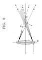
- a typical lens exhibits chromatism which is an aberration depending on the wavelength of an input light.
- the light input parallel to a convex lens 60 is theoretically focused at a focal point f.
- a red (R) light which has a relatively long wavelength focuses at a focal point F R which is a position farther than the focal point f of the convex lens 60
- a blue (B) light which has a relatively short wavelength focuses at a focal point F B which is a position closer than the focal point f of the convex lens 60.
- the color images with respect to red, green and blue colors formed by the first through third LCD panels 21, 23 and 25 of FIG. 1 focus on the screen 50 at different sizes. Also, as the difference in magnification is generated with respect to red, green and blue colors, a degree of mismatch of the red, green and blue color images increases at the periphery of the screen 50, thereby deteriorating the quality of image. Therefore, as the projection lens unit 40 necessarily has an additional optical structure to compensate for the above chromatism, the structure of the projector becomes complicated.
- the projection lens unit 40 should be designed considering distortion and field curvature of an image formed on the screen 50.
- the projection lens unit 40 is not able to perfectly correct both distortion and chromatism.
- an additional lens to correct chromatism is needed. In this case, however, it is a drawback that only a limited correction of chromatism is possible.
- a color projector comprising a light source, a splitting device for splitting the light emitted from the light source to proceed along first through third optical paths according to the wavelength thereof, first through third display devices, arranged on the first through third optical paths, for forming an image from an input light of a predetermined wavelength, a synthesizing means for synthesizing lights of different colors to proceed along one path by selectively transmitting or reflecting input lights passing through the first through third display devices according to the wavelength thereof, and a projection lens unit for magnifying and projecting a color image synthesized by the synthesizing device toward a screen, in which two or more display devices selected from the first through third display devices have the different sizes of effective areas where an image is formed such that chromatism generated while lights of different colors synthesized by the synthesizing device pass the projection lens unit can be corrected.
- a color projector comprising a light source, a splitting device for splitting the light emitted from the light source to proceed along first through third optical paths according to the wavelength thereof, first through third display devices, arranged on the first through third optical paths, for forming an image from an input light of a predetermined wavelength, a synthesizing means for synthesizing lights of different colors to proceed along one path by selectively transmitting or reflecting input lights passing through the first through third display devices according to the wavelength thereof, and a projection lens unit for magnifying and projecting a color image synthesized by the synthesizing device toward a screen, in which the distances between two or more display devices selected from the first through third display devices and the projection lens unit are different from one another such that chromatism generated while lights of different colors synthesized by the synthesizing device pass the projection lens unit can be corrected.
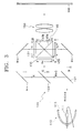
- a color projector includes a light source 110, a splitting device 120 for splitting the light emitted from the light source 110 to proceed along any of three paths according to the wavelength of the light, first through third display devices 131, 133 and 135, arranged on first through third optical paths I, II and III split by the splitting device 120, to form an image, a synthesizing device 140 for synthesizing the respective color lights to allow the synthesized light to proceed along one path by selectively transmitting or reflecting the input light passing through the first through third display devices 131, 133 and 135 according to the wavelength thereof, and a projection lens unit 150 for allowing the color image synthesized by the synthesizing device 140 to proceed toward a screen 160 by magnifying the same.
- the light source 110 includes a lamp 111 for generating light and a reflection mirror 113 for reflecting the light emitted from the lamp 111 and guiding a proceeding path of the reflected light.
- the reflection mirror 113 is an oval mirror having one focal point at the position of the lamp 111 and the other focal point at the position where light is focused, or a parabolic mirror having the focal point at the position of the lamp 111 for making the light reflected by the reflection mirror 113 a parallel beam.
- the splitting device 120 is for splitting the light emitted from the light source 110 to proceed along first through third optical paths I, II and III according to red (R), blue (B) and green (G) colors of the light.
- the splitting device 120 includes first and second dichromatic mirrors 121 and 123 and a plurality of total reflection mirrors M11, M12 and M13 for allowing the light split by the first and second dichromatic mirrors 121 and 123 to proceed along three different paths.
- the first dichromatic mirror 121 is for primarily splitting the light (R+G+B) emitted from the light source 110 according to the wavelength of the light.
- the first dichromatic mirror 121 transmits the light having the wavelength of blue (B) color to proceed along the third optical path III, and reflects the remaining light (R+G).
- the total reflection mirror M13 disposed on the third optical path III reflects the input blue (B) light to proceed toward the third display device 135.
- the light (R+G) reflected by the first dichromatic mirror 121 is split again by the second dichromatic mirror 123 according to the wavelength thereof. That is, the second dichromatic mirror 123 transmits the light having the wavelength of red (R) color to proceed along the first optical path I, and reflects the light of a green (G) color to proceed along the second optical path II.
- the total reflection mirrors M11 and M12 disposed along the first optical path I reflect the input red (R) light to proceed toward the first display device 131.
- the green (G) light passes along the second optical path II and is input to the second display device 133.
- the respective first through third display devices 131, 133 and 135 can be configured as a transmission type LCD device, as shown in FIG. 3.
- each of the first through third display devices 131, 133 and 135 forms an image with respect to red (R), green (G) and blue (B) colors
- chromatism is generated when the images of red (R), green (G) and blue (B) colors are synthesized by the synthesizing device 140 and pass through the projection lens unit 150 along the same optical path.
- the chromatism generated at the first through third display devices 131, 133 and 135 it is a characteristic feature that two or more display devices selected from the first through third display devices 131, 133 and 135 are different in the size of an effective area for generating an image.
- the distance g between each of the first through third display devices 131, 133 and 135 and a light input surface of the synthesizing device 140 is preferably the same.
- the first through third display devices 131, 133 and 135 have the same ratio in the size of an effective area, for example, 16:9. Assuming that the lengths of diagonal lines of the effective areas of the first, second and third display devices 131, 133 and 135 are S R , S G and S B , respectively, the lengths of the diagonal lines S R , S G and S B , satisfy the following Inequality 1. S B ⁇ S G ⁇ S R
- FIG. 5 is a view showing the first through third display devices 131, 133 and 135 by overlapping those in a state in which the synthesizing device 140 of FIG. 3 is excluded to explain a case in which the first through third display devices 131, 133 and 135 are separated the same optical distance away from the screen 160. Also, FIG. 5 schematically shows the projection lens unit 150 of FIG. 3.
- the light input to the projection lens unit 150 is refracted at different refraction angles at the projection lens unit 150 according to wavelength.
- the sizes of effective areas of the first through third display devices 131, 133 and 135 are set to be different from one another considering the different refraction angles, the size of an image with respect to each color, focused and diverged by the projection lens unit 150 and image-forming on the screen 160, can be matched.
- the difference in magnification with respect to red, green and blue colors at the screen 160 is barely generated so that deterioration of image quality due to chromatism can be prevented.
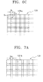
- each of the first through third display devices 131, 133 and 135 have a planar arrangement and a plurality of pixels 131a, 133a and 135a independently driven according to input video signals.
- the pixels 131 a, 133a and 135a of the first through third display devices 131, 133 and 135 preferably satisfy the Inequality 2.
- the distance D P between each pixel is preferably the same.
- the length of a diagonal line of each of the pixels 131 a forming the first display device 131 is S P1
- the length of a diagonal line of each of the pixels 133a forming the second display device 133 is S P2
- the length of a diagonal line of each of the pixels 135a forming the third display device 135 is S P3
- the lengths of diagonal lines S P1 , S P2 and S P3 of the respective pixels 131 a, 133a and 135a satisfy the following Inequality 2.
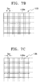
- each of the first through third display devices 131, 133 and 135 has a planar arrangement and includes a plurality of pixels 131b, 133b and 135b independently driven according to input video signals.
- each of the pixels 131b, 133b and 135b has the same size
- the synthesizing device 140 has three incident surfaces arranged to face the respective first through third display devices 131, 133 and 135, one exhaust surface arranged to face the projection lens unit 150, and first and second mirror surfaces 140a and 140b for selectively transmitting or reflecting the red, green and blue lights input along the first through third optical paths I, II and III.
- the first mirror surface 140a reflects the input red (R) light and transmits the green (g) and blue (B) lights.
- the second mirror surface 140b reflects the input blue (B) light toward the exhaust surface and transmits the red (R) and the green (G) lights.
- the light input to three incident surfaces along different paths is selectively transmitted or reflected at the first and second mirror surfaces 140a and 140b to proceed toward the screen 160 along the same path through the exhaust surface.
- the projection lens unit 150 arranged between the synthesizing device 140 and the screen 160 magnifies and projects the input color image.
- the projection lens unit 150 can be designed to adjust a design focus to correct distortion and field curvature of an image formed on the screen 160, a significant part of distortion which is easily discernible by a viewer can be corrected.
- a color projector includes a light source 110, a splitting device 120, first through third display devices 131', 133' and 135' arranged along first through third display devices I, II and III for forming an image, a synthesizing device 140 for synthesizing the input light passing through the first through third display devices 131', 133' and 135', and a projection lens unit 150.
- a light source 110 a splitting device 120
- first through third display devices 131', 133' and 135' arranged along first through third display devices I, II and III for forming an image
- a synthesizing device 140 for synthesizing the input light passing through the first through third display devices 131', 133' and 135'
- a projection lens unit 150 for synthesizing the input light passing through the first through third display devices 131', 133' and 135'
- a projection lens unit 150 for synthesizing the input light passing through the first through third display devices 131', 133' and 135'.
- the color projector according to the present embodiment is a device for correcting chromatism and has a characteristic feature in that the distances between two or more display devices selected from the first through third display devices 131', 133' and 135' and the projection lens unit 150 are set to be different from each other.
- Each of the first through third display devices 131', 133' and 135' has a planar arrangement and includes a transmission type LCD panel having a plurality of pixels independently driven according to the input video signals.
- the length of the width in one direction is d' such that the sizes of effective areas in image forming areas of the respective first through third display devices 131', 133' and 135' are the same.
- the distances therebetween are preferably set to be different from each other within a range of satisfying the conditions of Inequality 4.
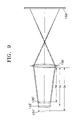
- FIG. 9 is for explaining a case in which the first through third display devices 131', 133' and 135' are of the same size and have different optical distances from the screen 160, in which the first through third display devices 131', 133' and 135' are arranged in one direction in a state in which the synthesizing device 140 is excluded. Also, the projection lens unit 150 is shown in FIG. 9 in a simplified state.
- the light input to the projection lens unit 150 is refracted at different refraction angles at the projection lens unit 150 according to wavelength.
- the distances between each of the first through third display devices 131', 133' and 135' and the incident surface of the projection lens unit 150 are D R , D G and D B , respectively, by setting the distances considering the different refraction angles, the size of an image with respect to each color, focused and diverged by the projection lens unit 150 and image-forming on the screen 160, can be matched.
- the projection lens unit 150 is designed without considering chromatism, the difference in magnification with respect to red, green and blue colors at the screen 160 is hardly generated so that deterioration of image quality due to chromatism can be prevented.
- a reflection type color projector include a light source 210, a splitting device 250 for splitting an input light according to the wavelength of the input light to proceed along each of the first through third optical paths I', II' and III', first through third optical path changing devices 261, 263 and 265 for changing the proceeding path of the split light according to the direction of polarization, first through third display devices 271, 273 and 275 for generating images from an input light of one polarization passing through the first through third optical path changing devices 261, 263 and 265 and reflecting the generated images toward the first through third optical path changing devices 261, 263 and 265, a synthesizing device 280 for synthesizing the input light after being reflected by the first through third display devices 271, 273 and 275, and a projection lens unit 290 for magnifying and projecting the color image synthesized by the synthesizing device 280 to be formed on the screen 160.
- the color projector preferably further comprises a bandpass filter 220 for blocking the light in the infrared and ultraviolet ranges of the light emitted from the light source 210, a uniform light illumination device 230 for making the input light a parallel beam, and a polarization converter 240 for converting the light emitted from the light source 210 to a light of one polarization, as shown in FIG. 10.
- a bandpass filter 220 for blocking the light in the infrared and ultraviolet ranges of the light emitted from the light source 210
- a uniform light illumination device 230 for making the input light a parallel beam
- a polarization converter 240 for converting the light emitted from the light source 210 to a light of one polarization, as shown in FIG. 10.
- the light source 210, the synthesizing device 280, and the projection lens unit 290 are substantially the same elements having the same functions as the light source 110, the synthesizing device 140 and the projection lens unit 150 of the color projector according to the first preferred embodiment of the present invention described with reference to FIG. 3, a detailed description thereof will be omitted.
- the splitting device 250 is for splitting the light emitted from the light source 210 to proceed along the first through third optical paths I', II' and III' according to the red (R), blue (B) and green (G) colors.
- the splitting device 250 includes first and second dichromatic mirrors 251 and 253, and a plurality of total reflection mirrors M 21 , M 22 and M 23 for allowing the lights split by the first and second dichromatic mirrors 251 and 253 to proceed along three different paths.
- the first dichromatic mirror 251 is for primarily splitting the light (R+G+B) emitted from the light source 110 according to the wavelength of the light.
- the light (B) of a blue wavelength is reflected by the first dichromatic mirror 251 and proceed along the third optical path III', and the remaining lights (R+G) pass through the first dichromatic mirror 251 thereby.
- the total reflection mirrors M 22 and M 23 are arranged on the third optical path III' and make the input blue light (B) to proceed toward the third optical path changing device 265.
- the red (R) light is input to the first optical path changing device 261 along the first optical path I' and the green (G) light is input to the second optical path changing device 263 along the second optical path II'.
- Each of the first through third display devices 271, 273 and 275 is comprised of a reflection type LCD device and a digital micro mirror device.
- the reflection type LCD device it is preferable to adopt a ferroelectric liquid crystal display (FLCD) device exhibiting a rapid response speed according to turning on/off of driving power, as the LCD device.
- FLCD ferroelectric liquid crystal display
- the digital micro mirror device corresponding to each pixel forms an image by determining the reflection path of input light by driving a plurality of reflection mirrors independently driven by applied electrostatic attraction.
- the configuration of the digital micro mirror device is well known, a detailed description thereof will be omitted.
- each of the reflection type first through third display devices 271, 273 and 275 forms an image with respect to the red (R), green (G) and blue (B) colors
- chromatism is generated when the light passes through the projection lens unit 290.
- the reflection type first through third display devices 271, 273 and 275 considering chromatism generated at the projection lens unit 290, have the characteristic feature in that the sizes of the effective areas for generating images of two or more display devices selected from the first through third display devices 271, 273 and 275 are different from each other.
- each of the first through third display devices 271, 273 and 275 has the same aspect ratio such as 16:9.
- the first through third optical path changing devices 261, 263 and 265 are polarization beam splitters for changing the optical path by selectively transmitting or reflecting the input light according to the polarization.
- the polarization beam splitter has a cubic or sheet structure, as shown in FIG. 10.
- a color projector according to a fourth preferred embodiment of the present invention has the same optical structure as the color projector of the third preferred embodiment of the present invention described with reference to FIG. 10, a drawing therefor will be omitted.
- the color projector of the fourth preferred embodiment has the characteristic feature in that the sizes of the reflection type first through third display devices 271, 273 and 275 are the same and the distance on the optical axis between each of the first through third display devices 271, 273 and 275 and the screen 160 are set to be different, so that chromatism can be corrected.
- the distances between each of the first through third display devices 271, 273 and 275 and the first incident surface of the projection lens unit 290 are D' R , D' G and D' B , by setting the distances therebetween considering the effect by chromatism, the size of image with respect to each color formed at the screen 160 after being focused and diverged by the projection lens unit 290 can be matched.
- the color projector according to the present invention even when chromatism generated while the lights of red, blue and green wavelengths pass through the projection lens unit, the generation of the difference in magnification with respect to red, green and blue colors is reduced by adjusting the size of and/or interval between the display devices, so that convergence is matched. Thus, deterioration of image quality can be prevented.
Landscapes
- Physics & Mathematics (AREA)
- General Physics & Mathematics (AREA)
- Optics & Photonics (AREA)
- Engineering & Computer Science (AREA)
- Multimedia (AREA)
- Signal Processing (AREA)
- Projection Apparatus (AREA)
- Liquid Crystal (AREA)
- Video Image Reproduction Devices For Color Tv Systems (AREA)
Applications Claiming Priority (2)
| Application Number | Priority Date | Filing Date | Title |
|---|---|---|---|
| KR9920483 | 1999-06-03 | ||
| KR1019990020483A KR100601608B1 (ko) | 1999-06-03 | 1999-06-03 | 칼라 프로젝트장치 |
Publications (3)
| Publication Number | Publication Date |
|---|---|
| EP1058461A2 true EP1058461A2 (de) | 2000-12-06 |
| EP1058461A3 EP1058461A3 (de) | 2003-08-06 |
| EP1058461B1 EP1058461B1 (de) | 2006-04-26 |
Family
ID=36371699
Family Applications (1)
| Application Number | Title | Priority Date | Filing Date |
|---|---|---|---|
| EP00111707A Expired - Lifetime EP1058461B1 (de) | 1999-06-03 | 2000-05-31 | Farbbildprojektor |
Country Status (6)
| Country | Link |
|---|---|
| US (1) | US6439724B1 (de) |
| EP (1) | EP1058461B1 (de) |
| JP (1) | JP3264916B2 (de) |
| KR (1) | KR100601608B1 (de) |
| CN (1) | CN1162731C (de) |
| DE (1) | DE60027502T2 (de) |
Cited By (2)
| Publication number | Priority date | Publication date | Assignee | Title |
|---|---|---|---|---|
| WO2004052024A1 (en) * | 2002-12-05 | 2004-06-17 | Koninklijke Philips Electronics N.V. | Device and method of color correction for projection type video image display devices |
| EP1460856A3 (de) * | 2003-03-20 | 2006-08-02 | Eastman Kodak Company | Projektionsapparat mit telezentrischer Optik |
Families Citing this family (20)
| Publication number | Priority date | Publication date | Assignee | Title |
|---|---|---|---|---|
| JP2002094822A (ja) * | 2000-09-13 | 2002-03-29 | Seiko Epson Corp | 補正カーブ生成方法、画像処理方法、画像表示装置および記録媒体 |
| US6827452B2 (en) * | 2002-12-30 | 2004-12-07 | Cinetron Technology Inc. | LCD projection system |
| KR100546644B1 (ko) * | 2003-04-04 | 2006-01-26 | 엘지전자 주식회사 | 반사형 조명 광학계 |
| KR100546604B1 (ko) * | 2003-04-29 | 2006-01-26 | 엘지전자 주식회사 | 디스플레이 장치 |
| US20050024577A1 (en) * | 2003-07-28 | 2005-02-03 | Ruey-Yau Tzong | Ferroelectric liquid crystal modulator applied in a liquid crystal projection device |
| US7293877B2 (en) | 2004-03-18 | 2007-11-13 | Kabushiki Kaisha Toshiba | Projecting apparatus and projecting and displaying apparatus |
| JP2006343692A (ja) * | 2005-06-10 | 2006-12-21 | Victor Co Of Japan Ltd | 投射表示装置 |
| JP4581755B2 (ja) * | 2004-04-30 | 2010-11-17 | 日本ビクター株式会社 | 投射表示装置 |
| JP5116288B2 (ja) | 2006-11-16 | 2013-01-09 | 株式会社リコー | 画像投影装置及び画像投影方法 |
| JP4341680B2 (ja) | 2007-01-22 | 2009-10-07 | セイコーエプソン株式会社 | プロジェクタ |
| JP5140869B2 (ja) | 2007-08-06 | 2013-02-13 | 株式会社リコー | 画像投影方法および画像投影装置 |
| DE102007042386A1 (de) * | 2007-09-04 | 2009-03-05 | Bundesdruckerei Gmbh | Verfahren und Vorrichtung zur individuellen farbigen holografischen Belichtung |
| JP5223452B2 (ja) | 2008-05-20 | 2013-06-26 | 株式会社リコー | プロジェクタ及び投影画像形成方法及び車両用ヘッドアップディスプレイ装置 |
| KR101620914B1 (ko) * | 2009-07-02 | 2016-05-17 | 삼성전자주식회사 | 광학 시스템 |
| JP6417478B2 (ja) * | 2015-07-17 | 2018-11-07 | マクセル株式会社 | 投写レンズの組み立て方法および投写映像表示装置 |
| KR101881078B1 (ko) | 2017-04-12 | 2018-07-24 | 주식회사 포스코건설 | 열풍로의 연락관 설치공법 |
| CN107809628B (zh) * | 2017-05-12 | 2024-05-28 | 杭州一隅千象科技有限公司 | 多方向环幕全覆盖的投影方法、投影仪及投影系统 |
| FR3068484B1 (fr) * | 2017-06-29 | 2019-11-22 | Commissariat A L'energie Atomique Et Aux Energies Alternatives | Projecteur couleur a deux ecrans emissifs. |
| CN107479199B (zh) * | 2017-08-04 | 2021-01-26 | 京东方科技集团股份有限公司 | 抬头显示装置及系统 |
| JP2021124527A (ja) * | 2020-01-31 | 2021-08-30 | セイコーエプソン株式会社 | 画像光生成モジュール及び画像表示装置 |
Family Cites Families (14)
| Publication number | Priority date | Publication date | Assignee | Title |
|---|---|---|---|---|
| JPH03175436A (ja) * | 1989-12-05 | 1991-07-30 | Matsushita Electric Ind Co Ltd | カラー画像投写装置と、その液晶表示装置 |
| JP2867529B2 (ja) * | 1990-01-22 | 1999-03-08 | 三菱電機株式会社 | 投写型表示装置 |
| KR950011004B1 (ko) * | 1992-02-22 | 1995-09-26 | 삼성전자주식회사 | 비디오 프로젝터용 프로젝션 렌즈 시스템 |
| JPH06222380A (ja) * | 1993-01-26 | 1994-08-12 | Mitsubishi Electric Corp | 投写形表示装置 |
| JP3189521B2 (ja) * | 1993-09-06 | 2001-07-16 | 株式会社日立製作所 | 色収差補正式投写形ディスプレイ |
| JPH0869062A (ja) * | 1994-08-30 | 1996-03-12 | Ricoh Opt Ind Co Ltd | カラー画像投影装置 |
| JPH08160374A (ja) * | 1994-12-01 | 1996-06-21 | Mitsubishi Electric Corp | プロジェクタ装置 |
| JPH08201756A (ja) * | 1995-01-26 | 1996-08-09 | Sharp Corp | 液晶プロジェクター |
| DE69608020T2 (de) * | 1995-03-16 | 2000-09-28 | Matsushita Electric Industrial Co., Ltd. | Videoprojektor |
| JPH10301077A (ja) * | 1997-04-28 | 1998-11-13 | Fujitsu Ltd | 液晶表示装置 |
| US6010221A (en) * | 1997-05-22 | 2000-01-04 | Nikon Corporation | Projection type display apparatus |
| JP3907799B2 (ja) * | 1997-09-26 | 2007-04-18 | フジノン株式会社 | 液晶プロジェクタ |
| US5921650A (en) * | 1998-02-27 | 1999-07-13 | International Business Machines Corporation | High efficiency field-sequential color projector using two SLMs |
| US6299312B1 (en) * | 2000-02-29 | 2001-10-09 | Samsung Electronics Co., Ltd. | Reflection type projector |
-
1999
- 1999-06-03 KR KR1019990020483A patent/KR100601608B1/ko not_active Expired - Fee Related
-
2000
- 2000-05-31 DE DE60027502T patent/DE60027502T2/de not_active Expired - Lifetime
- 2000-05-31 JP JP2000162398A patent/JP3264916B2/ja not_active Expired - Fee Related
- 2000-05-31 EP EP00111707A patent/EP1058461B1/de not_active Expired - Lifetime
- 2000-06-03 CN CNB001200178A patent/CN1162731C/zh not_active Expired - Fee Related
- 2000-06-05 US US09/586,749 patent/US6439724B1/en not_active Expired - Lifetime
Cited By (2)
| Publication number | Priority date | Publication date | Assignee | Title |
|---|---|---|---|---|
| WO2004052024A1 (en) * | 2002-12-05 | 2004-06-17 | Koninklijke Philips Electronics N.V. | Device and method of color correction for projection type video image display devices |
| EP1460856A3 (de) * | 2003-03-20 | 2006-08-02 | Eastman Kodak Company | Projektionsapparat mit telezentrischer Optik |
Also Published As
| Publication number | Publication date |
|---|---|
| DE60027502D1 (de) | 2006-06-01 |
| DE60027502T2 (de) | 2006-09-14 |
| CN1278072A (zh) | 2000-12-27 |
| US6439724B1 (en) | 2002-08-27 |
| EP1058461B1 (de) | 2006-04-26 |
| JP3264916B2 (ja) | 2002-03-11 |
| KR20010001337A (ko) | 2001-01-05 |
| EP1058461A3 (de) | 2003-08-06 |
| KR100601608B1 (ko) | 2006-07-14 |
| CN1162731C (zh) | 2004-08-18 |
| JP2001005098A (ja) | 2001-01-12 |
Similar Documents
| Publication | Publication Date | Title |
|---|---|---|
| US6439724B1 (en) | Color projector | |
| US6535256B1 (en) | Color liquid crystal display device | |
| US6457829B1 (en) | Projection device comprising a correction lens arranged between a prism optical system and at least one of three optical modulation elements | |
| US6450645B1 (en) | Reflection type projector including a sheet polarization beam splitter and a correction mechanism which corrects an aberration of the incident light caused by the sheet polarization beam splitter | |
| US20050063196A1 (en) | Light pipe based projection engine | |
| KR100364399B1 (ko) | 액정 프로젝터의 광학계 | |
| US7331680B2 (en) | Illumination unit and projection type image display apparatus employing the same | |
| US6773111B2 (en) | Projection type image display apparatus | |
| JP2867529B2 (ja) | 投写型表示装置 | |
| EP1052856A2 (de) | FARBProjektor vom Reflektionstyp | |
| US20110128503A1 (en) | Stereoscopic image projector | |
| KR100381050B1 (ko) | 액정 프로젝터의 광학계 | |
| KR100381051B1 (ko) | 액정 프로젝터의 광학계 | |
| EP1278381A2 (de) | Bildprojektionsgerät | |
| US5907373A (en) | Projection type color image display device | |
| US6616280B2 (en) | Projection type image display apparatus using reflection type liquid crystal display device | |
| EP1762882B1 (de) | Wellenlängenselektiver Polarisationsstrahlteiler | |
| JP3365618B2 (ja) | プロジェクタ装置 | |
| US7177084B2 (en) | Optical combining device | |
| JPH08201756A (ja) | 液晶プロジェクター | |
| US20040207769A1 (en) | Projection display device | |
| US6404559B1 (en) | Twin-lens projection display | |
| KR20010045715A (ko) | 칼라 프로젝트장치 | |
| KR0141548B1 (ko) | 액정 투사형 화상표시 장치 | |
| KR100312499B1 (ko) | 액정디스플레이프로젝터 |
Legal Events
| Date | Code | Title | Description |
|---|---|---|---|
| PUAI | Public reference made under article 153(3) epc to a published international application that has entered the european phase |
Free format text: ORIGINAL CODE: 0009012 |
|
| 17P | Request for examination filed |
Effective date: 20000531 |
|
| AK | Designated contracting states |
Kind code of ref document: A2 Designated state(s): AT BE CH CY DE DK ES FI FR GB GR IE IT LI LU MC NL PT SE |
|
| AX | Request for extension of the european patent |
Free format text: AL;LT;LV;MK;RO;SI |
|
| PUAL | Search report despatched |
Free format text: ORIGINAL CODE: 0009013 |
|
| AK | Designated contracting states |
Designated state(s): AT BE CH CY DE DK ES FI FR GB GR IE IT LI LU MC NL PT SE |
|
| AX | Request for extension of the european patent |
Extension state: AL LT LV MK RO SI |
|
| 17Q | First examination report despatched |
Effective date: 20040219 |
|
| AKX | Designation fees paid |
Designated state(s): DE FR GB NL |
|
| GRAP | Despatch of communication of intention to grant a patent |
Free format text: ORIGINAL CODE: EPIDOSNIGR1 |
|
| GRAS | Grant fee paid |
Free format text: ORIGINAL CODE: EPIDOSNIGR3 |
|
| GRAA | (expected) grant |
Free format text: ORIGINAL CODE: 0009210 |
|
| AK | Designated contracting states |
Kind code of ref document: B1 Designated state(s): DE FR GB NL |
|
| REG | Reference to a national code |
Ref country code: GB Ref legal event code: FG4D |
|
| REF | Corresponds to: |
Ref document number: 60027502 Country of ref document: DE Date of ref document: 20060601 Kind code of ref document: P |
|
| ET | Fr: translation filed | ||
| PLBE | No opposition filed within time limit |
Free format text: ORIGINAL CODE: 0009261 |
|
| STAA | Information on the status of an ep patent application or granted ep patent |
Free format text: STATUS: NO OPPOSITION FILED WITHIN TIME LIMIT |
|
| 26N | No opposition filed |
Effective date: 20070129 |
|
| REG | Reference to a national code |
Ref country code: FR Ref legal event code: PLFP Year of fee payment: 16 |
|
| PGFP | Annual fee paid to national office [announced via postgrant information from national office to epo] |
Ref country code: NL Payment date: 20150422 Year of fee payment: 16 |
|
| PGFP | Annual fee paid to national office [announced via postgrant information from national office to epo] |
Ref country code: GB Payment date: 20150422 Year of fee payment: 16 Ref country code: DE Payment date: 20150422 Year of fee payment: 16 |
|
| PGFP | Annual fee paid to national office [announced via postgrant information from national office to epo] |
Ref country code: FR Payment date: 20150422 Year of fee payment: 16 |
|
| REG | Reference to a national code |
Ref country code: DE Ref legal event code: R119 Ref document number: 60027502 Country of ref document: DE |
|
| REG | Reference to a national code |
Ref country code: NL Ref legal event code: MM Effective date: 20160601 |
|
| GBPC | Gb: european patent ceased through non-payment of renewal fee |
Effective date: 20160531 |
|
| PG25 | Lapsed in a contracting state [announced via postgrant information from national office to epo] |
Ref country code: NL Free format text: LAPSE BECAUSE OF NON-PAYMENT OF DUE FEES Effective date: 20160601 |
|
| REG | Reference to a national code |
Ref country code: FR Ref legal event code: ST Effective date: 20170131 |
|
| PG25 | Lapsed in a contracting state [announced via postgrant information from national office to epo] |
Ref country code: FR Free format text: LAPSE BECAUSE OF NON-PAYMENT OF DUE FEES Effective date: 20160531 Ref country code: DE Free format text: LAPSE BECAUSE OF NON-PAYMENT OF DUE FEES Effective date: 20161201 |
|
| PG25 | Lapsed in a contracting state [announced via postgrant information from national office to epo] |
Ref country code: GB Free format text: LAPSE BECAUSE OF NON-PAYMENT OF DUE FEES Effective date: 20160531 |