EP1059016B1 - Dynamische automatische verstärkungssteuerung in einem hörhilfegerät - Google Patents
Dynamische automatische verstärkungssteuerung in einem hörhilfegerät Download PDFInfo
- Publication number
- EP1059016B1 EP1059016B1 EP97950008A EP97950008A EP1059016B1 EP 1059016 B1 EP1059016 B1 EP 1059016B1 EP 97950008 A EP97950008 A EP 97950008A EP 97950008 A EP97950008 A EP 97950008A EP 1059016 B1 EP1059016 B1 EP 1059016B1
- Authority
- EP
- European Patent Office
- Prior art keywords
- input
- attack
- signal
- output
- adjustment
- Prior art date
- Legal status (The legal status is an assumption and is not a legal conclusion. Google has not performed a legal analysis and makes no representation as to the accuracy of the status listed.)
- Expired - Lifetime
Links
Images


Classifications
-
- H—ELECTRICITY
- H04—ELECTRIC COMMUNICATION TECHNIQUE
- H04R—LOUDSPEAKERS, MICROPHONES, GRAMOPHONE PICK-UPS OR LIKE ACOUSTIC ELECTROMECHANICAL TRANSDUCERS; ELECTRIC HEARING AIDS; PUBLIC ADDRESS SYSTEMS
- H04R25/00—Electric hearing aids
- H04R25/35—Electric hearing aids using translation techniques
- H04R25/356—Amplitude, e.g. amplitude shift or compression
-
- H—ELECTRICITY
- H04—ELECTRIC COMMUNICATION TECHNIQUE
- H04R—LOUDSPEAKERS, MICROPHONES, GRAMOPHONE PICK-UPS OR LIKE ACOUSTIC ELECTROMECHANICAL TRANSDUCERS; ELECTRIC HEARING AIDS; PUBLIC ADDRESS SYSTEMS
- H04R2225/00—Details of deaf aids covered by H04R25/00, not provided for in any of its subgroups
- H04R2225/41—Detection or adaptation of hearing aid parameters or programs to listening situation, e.g. pub, forest
-
- H—ELECTRICITY
- H04—ELECTRIC COMMUNICATION TECHNIQUE
- H04R—LOUDSPEAKERS, MICROPHONES, GRAMOPHONE PICK-UPS OR LIKE ACOUSTIC ELECTROMECHANICAL TRANSDUCERS; ELECTRIC HEARING AIDS; PUBLIC ADDRESS SYSTEMS
- H04R25/00—Electric hearing aids
- H04R25/50—Customised settings for obtaining desired overall acoustical characteristics
- H04R25/505—Customised settings for obtaining desired overall acoustical characteristics using digital signal processing
Definitions
- the invention relates to a method for automatic gain control in a hearing aid comprising at least one input signal transducer, a signal processor including at least one processing channel and an output signal transducer, said method comprising the steps of detecting an input signal from said input signal transducer and/or an output signal from said signal processor and adapting, within an operational range of said automatic gain control, said output sound level supplied by said output signal transducer in response to said detected sound level by controlling the gain of said signal processor towards an actual desired value of said output sound level, said gain control being effected at increases and decreases, respectively, of said input sound level by adjusting the gain towards said actual desired value with an attack time and a release time, respectively, whereby said release time is variable in response to changes in said received sound level.
- dashed line 1 illustrates the sound volume perception of a person having normal hearing as a function of the sound level received by the ear in the form of a straight line indicating sound perception with the same volume as the received sound.
- the solid curve 2 illustrates a typical example of the sound volume perception for a person having a hearing impairment.
- the hearing loss is dependant of the sound level and, normally also of frequency. With the illustrated hearing impairment the perception of sounds below a certain level K4 is significantly reduced and at a threshold level K3 the sound disappears completely.
- a linear, constant gain characteristic as illustrated by the curve 4 provides a natural sound perception, when the gain is adjusted to the actual listening situation or sound environment, but would require continuously repeated adjustment of the gain to the actual' situation, whereby operation of the hearing aid will become complicated and cumbersome. In result, hearing aids of this type are frequently not adjusted to an optimum sound perception for the actual listening situation.
- An improved hearing loss compensation can be obtained with a variable gain characteristic, e.g. as illustrated by the curve 6 in figure 1.
- This transfer function provides an expansion characteristic at low sound levels with maximum amplification of the received sound level at the knee point K2, whereby sound levels below this knee point are damped with increasing attenuation for decreasing level of the received sound.
- a compressor characteristic is provided causing decreasing amplification of received sound levels above knee point K2 up to knee point K4, thereby providing a compensation counteracting the hearing loss in this range, which is at the same time a critical range, within which silent speech or other sound may cause problems to hearing impaired persons, who will therefore benefit from this type of compensation approaching an ideal compensation.
- the transfer function will provide a substantially constant gain to provide compensation for the reduction in sound perception in this range.
- a compressor characteristic is provided, which may either be determined by the transfer function or result from clipping in the amplifier circuit. Beyond the knee point K5 the sound reproduction will often be selected to prevent sounds beyond the pain or discomfort limit to reach the ear.
- This distortion may be avoided and a more natural sound reproduction like the one obtainable with constant linear gain may be obtained by use of automatic gain control AGC with a quasi-linear amplification by which the gain will be continuously adapted to the actual received sound level with a smooth adjustment.
- the adaption is effected with time delays which according to IEC Standard No. 118-2 from 1983 are defined as an attack time and a release or recovery time.
- attack time is defined as the time interval from a sudden increase of the input signal level by a predetermined amount in dB until stabilization of the output level from the hearing aid with AGC within +/- 2 dB from the amplified steady-state output level.
- the release or recovery time is defined in the above-mentioned IEC standard as the time interval from a sudden decrease of the input signal level by a certain amount in dB until stabilization of the output signal level within +/- 2 dB from the lower steady-state output level.
- this form of AGC is implemented by detection of the received sound level or the output sound level and use of this detection to effect a smooth adjustment of the gain with the time delay, attack or release time, to the value desired for the actually detected sound level.
- the adjustment is effected by means of a compressor function as illustrated by the curve 5 in figure 1.
- gain adjustment is effected with an attack time
- gain adjustment is effected with a release or recovery time.
- the time delays are selected to provide a short attack time to prevent the user from receiving discomfortably high sound levels and a long release time to prevent pulsation or pumping of the sound level from reaching the ear.
- a release time of long duration for increasing the gain at a decrease in the detected received sound level has the disadvantage that when the user is exposed to a high sound level caused e.g. by the user shouting at a person situated remotely or a door is slammed nearby, the user will be unable to hear low sound levels during a period thereafter.
- the parameter or parameters of the input signal that are measured or detected to determine the detected sound level are important.
- these parameters may comprise peak value, average value, effective value or the like.
- a peak value detector produces a signal dependant on the peak values of the detected signal and provides a fast adjustment or short attack time at increasing received peak values, but a considerably slower adjustment or a relatively long release time at decreasing received peak values.
- Use of a peak value detecting circuit in conventional hearing aids having a transfer function as illustrated e.g. by the curve 5 in figure 1 provides the advantage of a quick damping of short heavy received sound levels in the form of noise pulses, but also the accompanying disadvantage that in case of speech signals containing high peak values spaced in time the gain will quickly be adjusted towards the peak values of the speech, whereby the speech is smoothed on the basis of the peak values and will attain the same level as received in speech pauses during which the sound is frequently noise.
- circuits In practice use is frequently made of combined circuits to determine or distinguish between received sound. Such circuits provide short attack time at increasing input level and acts like a peak value detector, whereas at stationary or decreasing input level they have a relatively longer release time and acts frequently as an average value detector.
- percentile detectors as known e.g. from EP-B1-0 732 036.
- percentile detectors serve to determine the value of the detected signal, at which predetermined percentages or percentiles of the detected signal are below or above the selected value, respectively.
- detectors are well suited to determine and separate noise from information signals.
- the average value detector At heavy sound levels of a longer duration the average value detector is excited and takes over the gain adjustment, After disappearance of the heavy sound pressure of longer duration following the taking over by the average value detector, the gain is adjusted slowly as a function of the decreasing mean value and during a time interval thereafter there will be an insufficient amplification of weak signals.
- this object is attained by a method as defined hereinbefore, which is characterized in that said attack and release times are adjusted in response to said detected sound level to a relatively short duration providing fast gain adjustment at high input and/or output sound levels and to a relatively long duration providing slow gain adjustment at low input and/or output sound levels.
- the sound will be controlled with long attack and release times at low sound levels, at which the transfer function provides a compressor characteristic and the reproduced sound is very sensitive to pumping or vibrating sound effects when the gain varies with time.
- the sound is controlled with short attack and release times at heavy sound levels at which the reproduced sound approaches the clipping or pain threshold.
- the method according to the invention provides the advantage that at a weak received sound change, which is heavier than the earlier detected sound change, there will be no immediate change of gain, as with a short attack time, but a gradual gain change with a relatively long time constant, whereby a short increase of sound will not lead to any significant gain change.
- the long attack time entails that sound increases at a low level will be reproduced more heavily during a time period after their generation than they ought to be according to the compression characteristic, this will in practice have the advantageous effect that the sound will not immediately change character due to a gain change in the range within which the received sound will be perceived as relatively weak both by a hearing impaired person and a person not having any hearing loss.
- the invention relates, moreover, to a hearing aid of the kind comprising at least one input signal transducer, a signal processor including at least one processing channel with associated gain control means and an output signal transducer, said hearing aid further comprising detecting means for detecting an input signal from said input signal transducer and/or an output signal from said output signal transducer and controlling said automatic gain control means in response to said detected sound level to adapt, within an operational range of said automatic gain control, the gain of said signal processor towards an actual desired value of said output sound level, said automatic gain control means including adjusting means to effect said gain control, at increases and decreases, respectively, of said input sound level, by adjustment of the gain towards said actual desired value with an attack time and a release time, respectively, where said release time is variable in response to changes in said input signal level.
- such a hearing aid is characterized in that said adjusting means is connected to said detecting means to receive a control signal therefrom to adjust said attack and release times in response to said detected sound level to a relatively short duration providing fast gain adjustment at high input and/or output sound levels and to a relatively long duration providing slow gain adjustment at low input/ and/or output sound levels.
- the reproduced sound will not exceed 60 dB, until the short attack and release times take over.
- FIG 9 an example of the switch-over of attack and release times at an input sound level of 60 dB is illustrated by the curve 6b as a change of slope measured in dB/sec for raise and fall-off rate.
- the curve 6b start at a received sound level of 25 dB to indicate that the expansion function below that level can be implemented outside the gain adjustment provided by the invention.
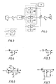
- FIG. 10 shows an embodiment of sound detecting and AGC gain adjusting means for use in a hearing aid according to the invention.
- the circuitry receives a preprocessed rectified signal and comprises a conventional leaking integrator device composed of an operation amplifier O1, a capacitor C and resistors R1 and R5 constituting a timing network.
- O1 operation amplifier
- R1 and R5 constituting a timing network.
- the circuitry further comprises a control circuit including comparators 25a and 25b, an OR gate Q and switches S1 and S2.
- a reference voltage source 25d supplies a reference voltage to one input of each of comparators 25a and 25b. If the input voltage supplied to the other input of comparator 25a or the output voltage supplied to the other input of comparator 25b is higher than the reference voltage, the actual comparator will supply an enabling signal to OR gate Q, which in response operates switches S1 and S2 to close, whereby resistors R1 and R5 are connected in parallel with resistors R1f and R5f, respectively, thus constituting a different timing network, and the short duration of the attack and release times will be determined by the time constants: ATTACK short : C*1/(1/R1 + 1/R5 + 1/ R1f + 1/R5f)
- RELEASE short C*1/ (1/R5 + 1/R5f)
- attack and release times can be selected to take account of pumping effects, whereby a relatively long attack time is particular advantageous to avoid pumping and insufficient amplification.
- attack and release times can be selected to take account of a fast dynamic control, whereby a relatively short attack time is particularly advantageous to avoid too early clipping or limitation and to provide for a faster gain decrease, so that sudden actuation of high gain is avoided, whereas a relatively short release time is advantageous for reducing the period during which controls signals remain inactive and actuating clipping or limitation and/or bring the control mode outside the range with insufficient amplification and down to a range with increased gain.
- a particular advantage of the method and hearing aid of the invention is the possibility of implementing the sound level detecting means in the form of socalled percentile estimators to provide different attack and release times without changing the percentile figure.
- a percentile estimating circuit is known from US-A-4,204,260 and for use in hearing aids from WO 96/35314.
- a percentile estimator functions in principle to provide a signal value forming the upper limit for a prescribed percentage of all input signal values, the percentile figure.
- a percentile estimator having a percentile figure of 50 supplies the signal value forming the upper limit for the input signal during 50 % of the time. Contrary to an average detector a percentile estimator is not affected by the signal wave shape above or below the percentile figure.
- FIG 11 an example is shown of circuitry for implementation of a percentile estimator having a percentile figure of 80.
- the circuit comprises an integrator device including an operation amplifier O1' and a capacitor C' to integrate the signal received from an input circuit comprising a comparator O2', resistors R1' and R2' and diodes D1 to D5.
- the comparator O2' receives at its non-inverting input the integrator output signal from integrator O1', C', whereas the input signal to be detected is supplied to the inverting input.
- the particular design of the detector itself is not essential to the operation of the hearing aid, and alternatively other conventional detecting circuits and functions may be used, the only requirement being that the detector supplies, as the actually detected sound level, a signal that can be processed by the subsequent circuitry, and that this output signal is supplied with a time delay which is sufficiently short to allow the following percentile estimator circuit to supply its output signal within the maximum time delay prescribed for the overall circuit, said time delay being e.g. 10 msec.
- the count-up and count-down regulation of integrator 24' are effected by quantities u and d supplied from the output 23o of the integrator control circuit 23 to the input 24i of the integrator 24'. Thereby, the integrator 24 is currently adjusted towards the signal value supplied from the detector as a representation of the actually detected sound level.
- the adjustment circuit may also have a single detecting input connected with the output 21o of detector 21 via control line f. Since the adjustment is effected, in this case, with a feed-forward arrangement it is possible to store a representation of the number of times or the duration of time, through which count-up adjustment has been effected with the short attack time to permit count-down adjustment with a short release time through the same period of time as used for the count-up adjustment. This may be effected by storing the counts with a short attack time in a separate fixed memory, and when the count in this memory is bigger than zero, the release time is set to the short duration, which is used to count-down the fixed memory and the integrator memory with the short release time, until the fixed memory reaches the value zero. Thereby, the short release time will be applied through an interval corresponding to the interval used for the short attack time.
- the adjustment circuit may also have a single detecting input connected with the output 24o of integrator 24' via control line b. Since in this case the adjustment is effected with a feed-back arrangement only, there will be a delay in going from long to short attack times, i.e. from slow to fast adjustment. This solution is advantageous to avoid a sudden decrease in gain or output sound level, when short noise pulses occur in normally quiet surroundings.
- the shift between different percentile figures is effected by stepwise or continuous adjustment of the values in integrator control circuit 23 and correction of the output value from the integrator control circuit for the change in percentile figure, since with usual signal values the 10 % percentile estimator will produce a smaller output signal than the 90 % percentile estimator.
- the figure shows a number of sound pulses P1 to P7 shifting between a low input signal level L1 below the 60 dB switch-over level and a high input signal level L2.
- the dash-and-dot line curve I below the 60 dB switch-over level illustrates the time delays resulting from the relatively long duration attack and release times used in this range.
- the dotted curve II illustrates the effect of time delays caused by relatively long duration attack and release times as used below the 60 dB level
- the dashed curve III illustrates the effect of using relatively short duration attack and release times in this range.
- a hearing aid according to the invention is assumed to have an excitation range of 120 dB for the detected sound pressure, a switch-over level at 60 dB for the change between short and long duration attack and release times, fast and slow release rates corresponding to changes in the detected sound pressure of 300 and 16 dB/sec, respectively, corresponding to short and long release max times of 0.4 and 7.5 sec., respectively, corresponding fast and slow attack rates of 1200 and 64 dB/sec, respectively, corresponding to short and long attack max times of 0.1 and 1.9 sec., respectively, and a transfer function as illustrated by the curve 6 in figure 1.
- conventional attack and short and long release times of 0.1, 0.4 and 7.5 sec. corresponding to attack and fast and slow release rates of 1200, 300 and 24 dB/sec are used.
- the hearing aid in this example with a maximum gain of 30 dB is in a receiving mode corresponding to a detected input sound level of 25 dB and receives a sound impulse of 0.2 sec duration and a level of 60 dB, which will not activate the short attack and release times, the detected sound level will be 38 dB, the gain after the noise pulse will be about 25 dB, and maximum gain will be restored after 0.8 sec. In this case, the listening level will not change materially, and there will be no pumping.
- the detected sound level will be 60 dB and the gain about 15 dB after the sound pulse, and by level controlled shift to the short release time maximum gain will be restored only after 2.2 sec.
Landscapes
- Health & Medical Sciences (AREA)
- General Health & Medical Sciences (AREA)
- Neurosurgery (AREA)
- Otolaryngology (AREA)
- Physics & Mathematics (AREA)
- Engineering & Computer Science (AREA)
- Acoustics & Sound (AREA)
- Signal Processing (AREA)
- Control Of Amplification And Gain Control (AREA)
- Tone Control, Compression And Expansion, Limiting Amplitude (AREA)
- Amplifiers (AREA)
Claims (24)
- Verfahren zur automatischen Verstärkungsregelung in einem Hörgerät mit wenigstens einem Eingangssignal-Wandler (11), einem Signalprozessor (15) einschließlich wenigstens eines Verarbeitungskanals (14a - 14c) und einem Ausgangssignal-Wandler (20), wobei das Verfahren die Schritte zum Erfassen eines Eingangssignals vom Eingangssignal-Wandler (11) und/oder eines Ausgangssignals vom Signalprozessor (15) und zum Anpassen, innerhalb eines Betriebsbereichs der automatischen Verstärkungsregelung, des durch den Ausgangssignal-Wandler (20) zugeführten Ausgangsklangpegels in Reaktion auf den erfassten Klangpegel durch Regeln der Verstärkung des Signalprozessors (15) in Richtung zu einem tatsächlichen erwünschten Wert des Ausgangsklangpegels aufweist, wobei die Verstärkungsregelung bei einem Größerwerden bzw. einem Kleinerwerden des Eingangsklangpegels durch Einstellen der Verstärkung in Richtung zum tatsächlichen erwünschten Wert mit einer Ansprechzeit bzw. einer Ausklingzeit bewirkt wird, wobei die Ausklingzeit in Reaktion auf Änderungen beim empfangenen Klangpegel variabel ist, dadurch gekennzeichnet, dass die Ansprech- und Ausklingzeiten in Reaktion auf den erfassten Klangpegel auf eine relativ kurze Dauer, was eine schnelle Verstärkungseinstellung bei hohen Eingangs- und/oder Ausgangsklangpegeln liefert, und auf eine relativ lange Dauer eingestellt werden, was eine langsame Verstärkungseinstellung bei niedrigen Eingangs- und/oder Ausgangsklangpegeln liefert.
- Verfahren nach Anspruch 1, dadurch gekennzeichnet, dass jede der Ansprech- und Ausklingzeiten entsprechend der kurzen bzw. der langen Dauer zwischen unterschiedlichen Werten umschaltbar ist.
- Verfahren nach Anspruch 1, dadurch gekennzeichnet, dass jede der Ansprech- und Ausklingzeiten in Abhängigkeit vom Eingangsklangpegel stufenweise oder kontinuierlich variabel ist.
- Verfahren nach Anspruch 2, dadurch gekennzeichnet, dass die Erfassung durch einen Vergleich der Eingangs- und/oder Ausgangssignale mit einem Referenzpegel bewirkt wird, um ein Regelsignal für die Einstellung der Ansprech- und Ausklingzeiten zu liefern.
- Verfahren nach Anspruch 4, dadurch gekennzeichnet, dass die Einstellung der Ansprech- und Ausklingzeiten mittels einer Integriererschaltung bewirkt wird, zu welcher das Regelsignal zugeführt wird, um eine Umschaltoperation zwischen Schaltungskonfigurationen der Integriererschaltung zu bewirken, was die unterschiedlichen Werte der Ansprech- und Wiedergewinnungszeiten liefert.
- Verfahren nach einem der Ansprüche 2 bis 4, dadurch gekennzeichnet, dass die Einstellung der Ansprech- und Wiedergewinnungszeiten durch Ändern von Percentil-Zeitverzögerungen in wenigstens einer Prozent-Abschätzschaltung bewirkt wird.
- Verfahren nach Anspruch 6, dadurch gekennzeichnet, dass die prozentualen Zeitverzögerungen geändert werden, um dasselbe Verhältnis zwischen der kurzen und der langen Dauer für die Ansprech- und die Ausklingzeiten zu liefern, ohne einen Percentil-Wert der Percentil-Abschätzeinheit zu ändern.
- Verfahren nach Anspruch 6, dadurch gekennzeichnet, dass die Percentil-Zeitverzögerungen geändert werden, um ein sich änderndes Verhältnis zwischen der kurzen und der langen Dauer für die Ansprech- und die Ausklingzeiten in Verbindung mit einem Ändern eines Percentil-Wertes der Percentil-Abschätzeinheit zu liefern.
- Verfahren nach einem der Ansprüche 1 bis 8, dadurch gekennzeichnet, dass ein Eingangssignal vom Eingangs-Wandler erfasst wird und dass die Einstellung der Ansprech- und Ausklingzeiten durch eine Vorwärtsregelung in bezug auf die automatische Verstärkungsregelung und/oder den Signalprozessor bewirkt wird.
- Verfahren nach einem der Ansprüche 1 bis 8, dadurch gekennzeichnet, dass ein Ausgangssignal vom Signalprozessor erfasst wird und dass die Einstellung der Ansprech- und Ausklingzeiten durch eine Rückkopplungssteuerung in bezug auf die automatische Verstärkungsregelung und/oder den Signalprozessor bewirkt wird.
- Verfahren nach einem der Ansprüche 1 bis 8, dadurch gekennzeichnet, dass die Einstellung der Ansprech- und Ausklingzeiten jeweils durch eine Vorwärtsregelung und eine Rückkopplung in bezug auf die automatische Verstärkungsregelung und/oder den Signalprozessor bewirkt wird.
- Verfahren nach einem der Ansprüche 1 bis 11 zur Verwendung in einem Hörgerät mit einem Digitalsignalprozessor, dadurch gekennzeichnet, dass die Einstellung der Ansprech- und Ausklingzeiten durch eine digitale Berechnung bewirkt wird.
- Verfahren nach einem der Ansprüche 1 bis 12 zur Verwendung in einem Hörgerät mit einem Signalprozessor mit mehreren Verarbeitungskanälen, dadurch gekennzeichnet, dass die Einstellung der Ansprech- und Ausklingzeiten in jedem der Verarbeitungskanäle individuell bewirkt wird.
- Verfahren nach einem der Ansprüche 1 bis 13 zur Verwendung in einem Hörgerät mit einer Expansions- oder Kompressions-Verstärkungscharakteristik bei niedrigen Eingangsklangpegeln bis zu einem vorbestimmten Knickstellenpegel und einer im wesentlichen konstanten Verstärkung oder einem Kompressionsverhältnis bei Klangpegeln oberhalb des Knickstellenpegels, dadurch gekennzeichnet, dass die Einstellung der Ansprech- und Ausklingzeiten auf die relativ kurze Dauer nur für Klangpegel oberhalb des Knickstellenpegels in Betrieb genommen wird.
- Hörgerät mit wenigstens einem Eingangssignal-Wandler (11), einem Signalprozessor (15) einschließlich wenigstens eines Verarbeitungskanals (14a-14c) mit einer zugehörigen Verstärkungsregelungseinrichtung und einem Ausgangssignal-Wandler (20), wobei das Hörgerät weiterhin eine Erfassungseinrichtung (16) zum Erfassen eines Eingangssignals vom Eingangssignal-Wandler (11) und/oder eines Ausgangssignals vom Signalprozessor (15) und zum Regeln der automatischen Verstärkungsregelungseinrichtung in Reaktion auf den erfassten Klangpegel aufweist, um innerhalb eines Betriebsbereichs der automatischen Verstärkungsregelung die Verstärkung des Signalprozessors (15) in Richtung zu einem tatsächlichen erwünschten Wert des Ausgangsklangpegels anzupassen, wobei die automatische Verstärkungsregelungseinrichtung eine Einstelleinrichtung (01, 01', 24, 24') enthält, um die Verstärkungsregelung bei einem Größerwerden bzw. einem Kleinerwerden des Eingangsklangpegels durch eine Einstellung der Verstärkung in Richtung zum tatsächlichen erwünschten Wert mit einer Ansprechzeit bzw. einer Ausklingzeit zu bewirken, wobei die Ausklingzeit in Reaktion auf Änderungen bezüglich des Eingangssignalpegels variabel ist, dadurch gekennzeichnet, dass die Einstelleinrichtung (01, 01', 24, 24') mit der Erfassungseinrichtung (16) verbunden ist, um ein Regelsignal von ihr zu empfangen, um die Ansprech- und Ausklingzeiten in Reaktion auf den erfassten Klangpegel auf eine relativ kurze Dauer, was eine schnelle Verstärkungseinstellung bei hohen Eingangs- und/oder Ausgangsklangpegeln liefert, und auf eine relativ lange Dauer einzustellen, was eine langsame Verstärkungseinstellung bei niedrigen Eingangs- und/oder Ausgangsklangpegeln liefert.
- Hörgerät nach Anspruch 15, dadurch gekennzeichnet, dass die Erfassungseinrichtung zwei Komparatoren (25a, 25b, 25a', 25b') aufweist, um ein Eingangssignal entsprechend dem Eingangsklangpegel bzw. ein Ausgangssignal entsprechend dem Ausgangsklangpegel bei einem Eingang zu empfangen, wobei ein anderer Eingang beider Komparatoren (25a, 25b, 25a', 25b') mit einer Referenzsignalquelle (25d, 25d') verbunden ist, um einen Referenzsignalpegel von ihr zu empfangen, wobei eine Regelungseinrichtung mit einem gemeinsamen Gate (Q, Q') mit den Ausgängen der Komparatoren (25a, 25b, 25a', 25b) verbunden ist und einen Ausgang hat, um ein erstes Regelsignal für die Einstelleinrichtung zuzuführen, wenn beide der Eingangs- oder Ausgangssignale unter dem Referenzsignalpegel sind, und um ein zweites Regelsignal für die Einstelleinrichtung zu liefern, wenn irgendeines der Eingangs- oder Ausgangssignale oberhalb des Referenzsignalpegels ist.
- Hörgerät nach Anspruch 16, dadurch gekennzeichnet, dass die Einstelleinrichtung eine Integriererschaltung (O') aufweist, die zwei Zeitgabenetzwerke (C, R1, R5, R1F, R5F) enthält, um jeweils die Ansprechzeit und die Ausklingzeit zu liefern, und eine Kontakteinrichtung (S1, S2), die mit der Gate-Regelungseinrichtung (Q) verbunden ist, um das erste und das zweite Regelsignal von ihr zu empfangen, um jedes der Netzwerke zwischen jeweils einer ersten und einer zweiten Schaltungskonfiguration umzuschalten, um jeweils einen bestimmten Wert für die relativ kurze Dauer oder einen bestimmten Wert für die relativ lange Dauer der Ansprech- und Ausklingzeiten zu liefern.
- Hörgerät nach Anspruch 16, dadurch gekennzeichnet, dass die Einstelleinrichtung eine Procentil-Abschätzeinheit aufweist, die einen Komparator (O2) und eine mit einem Ausgang des Komparators (O2) verbundene Integriererschaltung (O1', 24) enthält, wobei ein Ausgang der Integriererschaltung (24) mit einem ersten Eingang des Komparators (O2) verbunden ist, von welchem ein zweiter Eingang ein Eingangssignal entsprechend dem Eingangsklangpegel empfängt, wobei der Ausgang des Komparators (O2) mit der Integrierer-Regelungseinrichtung (D1-D5) verbunden ist, die eine erste oder eine zweite Regelungsspannung für die Integriererschaltung in Reaktion auf ein Ausgangssignal vom Komparator (O2) liefert, wobei ein mit der Regelungseinrichtung verbundenes Zeitgabenetzwerk (C", R1", R2", R3") durch eine Schalteinrichtung (S1) zwischen ersten und zweiten Konfigurationen umschaltbar ist, die durch die Gate-Regelungseinrichtung (Q1) geregelt wird, um maximale Werte der Ansprech- und Ausklingzeiten jeweils für die lange Dauer bzw. die kurze Dauer zu liefern.
- Hörgerät nach Anspruch 15, dadurch gekennzeichnet, dass die Einstelleinrichtung der automatischen Verstärkungsregelungseinrichtung eine Percentil-Abschätzeinheit (24') einschließlich eines Komparators (22) aufweist, der einen ersten Eingang hat, der mit der Erfassungseinrichtung (21) verbunden ist, und einen zweiten Eingang sowie Aufwärtszähl- und Abwärtszähl-Ausgänge (u, d), wobei eine Integriererschaltung (24') einen Eingang hat, der mit einem Ausgang einer Integrierer-Regelungsschaltung (23) verbunden ist, die die Aufwärtszähl- und Abwärtszähl-Ausgangssignale vom Komparator (22) empfängt, wobei die Integrierer-Regelungsschaltung (23) durch eine Percentil-Regelungsschaltung (25') geregelt wird, die einen ersten Eingang hat, der mit der Erfassungseinrichtung (21) verbunden ist, wohingegen der zweite Eingang des Komparators (22) und ein zweiter Eingang der Percentil-Regelungsschaltung (25') mit einem Ausgang der Integriererschaltung (24') verbunden sind, welcher weiterhin mit dem Signalprozessor zum Zuführen eines Verstärkungsregelungssignals zu ihm verbunden ist.
- Hörgerät nach Anspruch 19, dadurch gekennzeichnet, dass die Erfassungseinrichtung (16) mit dem Eingangssignal-Wandler (11) zur Vorwärtsregelung des Signalprozessors verbunden ist.
- Hörgerät nach Anspruch 19, dadurch gekennzeichnet, dass die Erfassungseinrichtung (16) mit dem Ausgang des Signalprozessors (15) zur Rückkopplung des Signalprozessors verbunden ist.
- Hörgerät nach einem der Ansprüche 19 bis 21, dadurch gekennzeichnet, dass der Signalprozessor ein Digitalsignalprozessor ist, der die Percentil-Abschätzeinheit enthält.
- Hörgerät nach einem der Ansprüche 15 bis 21, dadurch gekennzeichnet, dass der Signalprozessor mehrere Verarbeitungskanäle (14a, 14c) mit einzelnen automatischen Verstärkungsregelungseinrichtungen, Erfassungseinrichtungen und Verstärkungsregelungs-Einstelleinrichtungen enthält.
- Hörgerät nach einem der Ansprüche 15 bis 23, wobei der Signalprozessor (15) eine Expansions- oder Kompressionscharakteristik für niedrige Eingangsklangpegel bis zu einer vorbestimmten Knickstelle hat, und eine im wesentlichen konstante Verstärkung oder ein Kompressionsverhältnis für Klangpegel oberhalb der Knickstelle, dadurch gekennzeichnet, dass die Verstärkungsregelungs-Einstelleinrichtung eine Einrichtung enthält, um eine Einstellung der Ansprech- und Ausklingzeiten auf die relativ kurze Dauer nur für Klangpegel oberhalb der Knickstelle zu ermöglichen.
Applications Claiming Priority (1)
| Application Number | Priority Date | Filing Date | Title |
|---|---|---|---|
| PCT/DK1997/000598 WO1999034642A1 (en) | 1997-12-23 | 1997-12-23 | Dynamic automatic gain control in a hearing aid |
Publications (2)
| Publication Number | Publication Date |
|---|---|
| EP1059016A1 EP1059016A1 (de) | 2000-12-13 |
| EP1059016B1 true EP1059016B1 (de) | 2002-05-22 |
Family
ID=8156342
Family Applications (1)
| Application Number | Title | Priority Date | Filing Date |
|---|---|---|---|
| EP97950008A Expired - Lifetime EP1059016B1 (de) | 1997-12-23 | 1997-12-23 | Dynamische automatische verstärkungssteuerung in einem hörhilfegerät |
Country Status (9)
| Country | Link |
|---|---|
| US (1) | US6628795B1 (de) |
| EP (1) | EP1059016B1 (de) |
| JP (1) | JP3670962B2 (de) |
| AT (1) | ATE218028T1 (de) |
| AU (1) | AU739344B2 (de) |
| CA (1) | CA2316242C (de) |
| DE (1) | DE69712801T2 (de) |
| DK (1) | DK1059016T3 (de) |
| WO (1) | WO1999034642A1 (de) |
Cited By (3)
| Publication number | Priority date | Publication date | Assignee | Title |
|---|---|---|---|---|
| US8290190B2 (en) | 2008-09-10 | 2012-10-16 | Widex A/S | Method for sound processing in a hearing aid and a hearing aid |
| US8885838B2 (en) | 2009-12-09 | 2014-11-11 | Widex A/S | Method of processing a signal in a hearing aid, a method of fitting a hearing aid and a hearing aid |
| WO2026013311A1 (en) | 2024-07-11 | 2026-01-15 | Widex A/S | Method of operating a hearing aid system and a hearing aid system |
Families Citing this family (42)
| Publication number | Priority date | Publication date | Assignee | Title |
|---|---|---|---|---|
| ATE383730T1 (de) | 1998-02-18 | 2008-01-15 | Widex As | Binaurales digitales hörhilfesystem |
| JP3953814B2 (ja) | 1999-10-07 | 2007-08-08 | ヴェーデクス・アクティーセルスカプ | 補聴器におけるスピーチ信号成分を増強するための方法および信号処理装置 |
| US6445233B1 (en) * | 1999-12-30 | 2002-09-03 | The Engineering Consortium, Inc. | Multiple time constant rectifier apparatus and method |
| US6731768B1 (en) * | 2000-07-26 | 2004-05-04 | Etymotic Research, Inc. | Hearing aid having switched release automatic gain control |
| US7489790B2 (en) * | 2000-12-05 | 2009-02-10 | Ami Semiconductor, Inc. | Digital automatic gain control |
| US20030023429A1 (en) * | 2000-12-20 | 2003-01-30 | Octiv, Inc. | Digital signal processing techniques for improving audio clarity and intelligibility |
| US20030007657A1 (en) | 2001-07-09 | 2003-01-09 | Topholm & Westermann Aps | Hearing aid with sudden sound alert |
| WO2001076063A2 (de) * | 2001-08-08 | 2001-10-11 | Phonak Ag | Verfahren zur verarbeitung eines eingangssignals zur erzeugung eines ausgangssignals und eine anwendung des verfahrens bei hörhilfen bzw. hörgeräten |
| EP1440603A2 (de) * | 2001-10-17 | 2004-07-28 | Koninklijke Philips Electronics N.V. | Gerät zur verstärkung von bass frequenzen |
| US7333623B2 (en) | 2002-03-26 | 2008-02-19 | Oticon A/S | Method for dynamic determination of time constants, method for level detection, method for compressing an electric audio signal and hearing aid, wherein the method for compression is used |
| DK1351550T3 (da) | 2002-09-10 | 2011-02-28 | Phonak Ag | Fremgangsmåde og tilpasning af en signalforstærkning i et høreapparat samt et høreapparat |
| JP4640948B2 (ja) * | 2004-06-17 | 2011-03-02 | ローム株式会社 | Alc付き増幅装置およびそれを用いた電子機器 |
| DE102004044565B4 (de) * | 2004-09-15 | 2007-08-02 | Carl Von Ossietzky Universität Oldenburg | Verfahren zur Begrenzung des Dynamikbereichs von Audiosignalen und Schaltungsanordnung hierzu |
| WO2006102892A1 (en) * | 2005-03-29 | 2006-10-05 | Gn Resound A/S | Hearing aid with adaptive compressor time constants |
| DE102005034647B3 (de) * | 2005-07-25 | 2007-02-22 | Siemens Audiologische Technik Gmbh | Hörvorrichtung und Verfahren zur Einstellung einer Verstärkungskennlinie |
| AU2005337523B2 (en) * | 2005-10-18 | 2009-09-10 | Widex A/S | Hearing aid comprising a data logger and method of operating the hearing aid |
| EP1802168B1 (de) | 2005-12-21 | 2022-09-14 | Oticon A/S | Systeme zur Steuerung der Übertragungsfunktion eines Hörgeräts |
| DE102006007779B4 (de) * | 2006-02-20 | 2008-07-10 | Infineon Technologies Ag | Filterbank-Anordnung und Signalverarbeitungs-Vorrichtung |
| EP1773099A1 (de) * | 2006-05-30 | 2007-04-11 | Phonak AG | Verfahren und System zur Hörhilfebereitstellung für einen Benutzer |
| DE102006051071B4 (de) | 2006-10-30 | 2010-12-16 | Siemens Audiologische Technik Gmbh | Pegelabhängige Geräuschreduktion |
| DK1981309T3 (da) | 2007-04-11 | 2012-04-23 | Oticon As | Høreapparat med flerkanalskompression |
| US20090060209A1 (en) * | 2007-08-31 | 2009-03-05 | Victor Company Of Japan, Ltd. A Corporation Of Japan | Audio-signal processing apparatus and method |
| US8284971B2 (en) * | 2008-11-21 | 2012-10-09 | Envoy Medical Corporation | Logarithmic compression systems and methods for hearing amplification |
| JP5531988B2 (ja) * | 2011-03-03 | 2014-06-25 | 株式会社Jvcケンウッド | 音量制御装置、音量制御方法、および音量制御プログラム |
| DK2512157T3 (en) | 2011-04-13 | 2014-02-17 | Oticon As | Hearing aid with automatic speech clipping prevention and similar procedure |
| US20120262233A1 (en) * | 2011-04-15 | 2012-10-18 | Fairchild Semiconductor Corporation | Mixed signal dynamic range compression |
| JP5872687B2 (ja) | 2011-06-01 | 2016-03-01 | エプコス アーゲーEpcos Ag | アナログデータ処理ユニットを備えるアセンブリ及び当該アセンブリを使用する方法 |
| EP2795924B1 (de) | 2011-12-22 | 2016-03-02 | Widex A/S | Verfahren zum betrieb eines hörgeräts und hörgerät |
| DK2820863T3 (en) | 2011-12-22 | 2016-08-01 | Widex As | Method of operating a hearing aid and a hearing aid |
| EP2658120B1 (de) * | 2012-04-25 | 2016-04-13 | GN Resound A/S | Hörgerät mit verbesserter Kompression |
| US8913768B2 (en) | 2012-04-25 | 2014-12-16 | Gn Resound A/S | Hearing aid with improved compression |
| WO2014094865A1 (en) | 2012-12-21 | 2014-06-26 | Widex A/S | Method of operating a hearing aid and a hearing aid |
| US9900708B2 (en) * | 2013-12-27 | 2018-02-20 | Gn Hearing A/S | Hearing instrument with switchable power supply voltage |
| EP3534625A1 (de) | 2015-12-23 | 2019-09-04 | GN Hearing A/S | Hörgerät mit unterdrückung von schallimpulsen |
| DE102016221692B3 (de) | 2016-11-04 | 2017-12-07 | Sivantos Pte. Ltd. | Verfahren zum Betrieb eines Hörgeräts |
| US11253193B2 (en) * | 2016-11-08 | 2022-02-22 | Cochlear Limited | Utilization of vocal acoustic biomarkers for assistive listening device utilization |
| HK1250122A2 (zh) * | 2018-07-24 | 2018-11-23 | HearSafe Limited | 听觉保护装置及方法 |
| US11641183B2 (en) * | 2018-10-25 | 2023-05-02 | Ear Physics, Llc | Audio dynamics processing control system with integration release window |
| EP4127620A4 (de) | 2020-03-30 | 2023-09-06 | Blackbox Biometrics, Inc. | Akustische überwachungssysteme und verfahren |
| CN111479204B (zh) * | 2020-04-14 | 2021-09-03 | 上海力声特医学科技有限公司 | 适用于人工耳蜗的增益调节方法 |
| PL442201A1 (pl) * | 2022-09-05 | 2024-03-11 | Centralny Instytut Ochrony Pracy - Państwowy Instytut Badawczy | Elektroniczny system przekazywania dźwięku pod ochronnik słuchu |
| WO2025120225A1 (en) | 2023-12-08 | 2025-06-12 | Widex A/S | Method of operating a hearing aid system and a hearing aid system |
Family Cites Families (12)
| Publication number | Priority date | Publication date | Assignee | Title |
|---|---|---|---|---|
| US4204260A (en) | 1977-06-14 | 1980-05-20 | Unisearch Limited | Recursive percentile estimator |
| US4531229A (en) | 1982-10-22 | 1985-07-23 | Coulter Associates, Inc. | Method and apparatus for improving binaural hearing |
| US4718099A (en) | 1986-01-29 | 1988-01-05 | Telex Communications, Inc. | Automatic gain control for hearing aid |
| GB2192511B (en) | 1986-07-11 | 1990-02-21 | Roger Frederick Laurence | Hearing aid |
| US5165017A (en) | 1986-12-11 | 1992-11-17 | Smith & Nephew Richards, Inc. | Automatic gain control circuit in a feed forward configuration |
| US5144675A (en) | 1990-03-30 | 1992-09-01 | Etymotic Research, Inc. | Variable recovery time circuit for use with wide dynamic range automatic gain control for hearing aid |
| DE4228934C2 (de) * | 1992-08-31 | 1994-08-11 | Alois Dipl Phys Dr Heis | Vorrichtung zur Bestimmung des Vertrauensbereichs von Perzentil-Meßwerten kontinuierlicher stochastischer Schallsignale |
| US5402498A (en) * | 1993-10-04 | 1995-03-28 | Waller, Jr.; James K. | Automatic intelligent audio-tracking response circuit |
| DE4340817A1 (de) * | 1993-12-01 | 1995-06-08 | Toepholm & Westermann | Schaltungsanordnung für die automatische Regelung von Hörhilfsgeräten |
| DK0824845T3 (da) | 1995-05-02 | 1999-06-21 | Toepholm & Westermann | Fremgangsmåde til styring af et programmerbart eller programstyret høreapparat til dettes in situ tilpasningsjustering |
| US5832097A (en) | 1995-09-19 | 1998-11-03 | Gennum Corporation | Multi-channel synchronous companding system |
| US5903655A (en) * | 1996-10-23 | 1999-05-11 | Telex Communications, Inc. | Compression systems for hearing aids |
-
1997
- 1997-12-23 JP JP2000527123A patent/JP3670962B2/ja not_active Expired - Fee Related
- 1997-12-23 US US09/581,636 patent/US6628795B1/en not_active Expired - Lifetime
- 1997-12-23 EP EP97950008A patent/EP1059016B1/de not_active Expired - Lifetime
- 1997-12-23 WO PCT/DK1997/000598 patent/WO1999034642A1/en not_active Ceased
- 1997-12-23 DK DK97950008T patent/DK1059016T3/da active
- 1997-12-23 CA CA002316242A patent/CA2316242C/en not_active Expired - Fee Related
- 1997-12-23 AU AU53119/98A patent/AU739344B2/en not_active Ceased
- 1997-12-23 AT AT97950008T patent/ATE218028T1/de not_active IP Right Cessation
- 1997-12-23 DE DE69712801T patent/DE69712801T2/de not_active Expired - Lifetime
Cited By (3)
| Publication number | Priority date | Publication date | Assignee | Title |
|---|---|---|---|---|
| US8290190B2 (en) | 2008-09-10 | 2012-10-16 | Widex A/S | Method for sound processing in a hearing aid and a hearing aid |
| US8885838B2 (en) | 2009-12-09 | 2014-11-11 | Widex A/S | Method of processing a signal in a hearing aid, a method of fitting a hearing aid and a hearing aid |
| WO2026013311A1 (en) | 2024-07-11 | 2026-01-15 | Widex A/S | Method of operating a hearing aid system and a hearing aid system |
Also Published As
| Publication number | Publication date |
|---|---|
| CA2316242A1 (en) | 1999-07-08 |
| EP1059016A1 (de) | 2000-12-13 |
| JP2002500494A (ja) | 2002-01-08 |
| CA2316242C (en) | 2003-10-28 |
| US6628795B1 (en) | 2003-09-30 |
| WO1999034642A1 (en) | 1999-07-08 |
| DK1059016T3 (da) | 2002-09-09 |
| JP3670962B2 (ja) | 2005-07-13 |
| ATE218028T1 (de) | 2002-06-15 |
| DE69712801T2 (de) | 2002-11-07 |
| AU739344B2 (en) | 2001-10-11 |
| AU5311998A (en) | 1999-07-19 |
| DE69712801D1 (de) | 2002-06-27 |
Similar Documents
| Publication | Publication Date | Title |
|---|---|---|
| EP1059016B1 (de) | Dynamische automatische verstärkungssteuerung in einem hörhilfegerät | |
| US4852175A (en) | Hearing aid signal-processing system | |
| US5553151A (en) | Electroacoustic speech intelligibility enhancement method and apparatus | |
| US6563931B1 (en) | Auditory prosthesis for adaptively filtering selected auditory component by user activation and method for doing same | |
| EP1210767B1 (de) | Verfahren und vorrichtung zum automatischen einstellen der verstärkungen des mikrophon- und sprecherverstärkers in einem tragbaren telefon | |
| US7995781B2 (en) | Method for operating a hearing device as well as a hearing device | |
| EP0648397B1 (de) | Ausfallgesichertes betriebsverfahren in einem lautfernsprechsystem | |
| CA2268918C (en) | Compression systems for hearing aids | |
| EP1219138B1 (de) | Verfahren und signalprozessor zur verstärkung von sprachsignal-komponenten in einem hörhilfegerät | |
| CN106911993B (zh) | 具有声音脉冲抑制的听力装置 | |
| WO2003081947A1 (en) | Method for dynamic determination of time constants, method for level detection, method for compressing an electric audio signal and hearing aid, wherein the method for compression is used | |
| AU615822B2 (en) | Acoustic calibration arrangement for a voice switched speakerphone | |
| US4887288A (en) | Self calibration arrangement for a voice switched speakerphone | |
| EP1120008A2 (de) | Rückkopplungsbehandlung für ein hörgerät | |
| US4979163A (en) | Echo suppression arrangement for an adaptive speakerphone | |
| CA2294713A1 (en) | Hearing aid having input agc and output agc | |
| EP1811660B1 (de) | Verfahren und Vorrichtung zum automatischen Einstellen der Verstärkung des Sprecherverstärkers in einem tragbaren Telephon | |
| WO1999005840A1 (en) | Method and apparatus for automatically adjusting speaker and microphone gains within a mobile telephone | |
| EP0813331A2 (de) | Vorrichtung und Verfahren zur Benutzersteuerung des Lautstärkeschwellwertes für Zustandumschaltung in einem Halbduplex-Lautfernsprecher | |
| WO1999011047A1 (en) | Method and apparatus for listener sidetone control | |
| US6516068B1 (en) | Microphone expander | |
| US6433633B1 (en) | Automatic gain control system with signal presence conditioning | |
| Nordqvist et al. | Hearing-aid automatic gain control adapting to two sound sources in the environment, using three time constants | |
| HK1112330A (en) | Method and apparatus for automatically adjusting speaker gain within a mobile telephone |
Legal Events
| Date | Code | Title | Description |
|---|---|---|---|
| PUAI | Public reference made under article 153(3) epc to a published international application that has entered the european phase |
Free format text: ORIGINAL CODE: 0009012 |
|
| 17P | Request for examination filed |
Effective date: 20000614 |
|
| AK | Designated contracting states |
Kind code of ref document: A1 Designated state(s): AT CH DE DK FR GB IT LI |
|
| GRAG | Despatch of communication of intention to grant |
Free format text: ORIGINAL CODE: EPIDOS AGRA |
|
| 17Q | First examination report despatched |
Effective date: 20010918 |
|
| GRAG | Despatch of communication of intention to grant |
Free format text: ORIGINAL CODE: EPIDOS AGRA |
|
| GRAH | Despatch of communication of intention to grant a patent |
Free format text: ORIGINAL CODE: EPIDOS IGRA |
|
| GRAH | Despatch of communication of intention to grant a patent |
Free format text: ORIGINAL CODE: EPIDOS IGRA |
|
| RAP1 | Party data changed (applicant data changed or rights of an application transferred) |
Owner name: WIDEX A/S |
|
| GRAA | (expected) grant |
Free format text: ORIGINAL CODE: 0009210 |
|
| REF | Corresponds to: |
Ref document number: 218028 Country of ref document: AT Date of ref document: 20020615 Kind code of ref document: T |
|
| REG | Reference to a national code |
Ref country code: GB Ref legal event code: FG4D |
|
| REG | Reference to a national code |
Ref country code: CH Ref legal event code: EP |
|
| REF | Corresponds to: |
Ref document number: 69712801 Country of ref document: DE Date of ref document: 20020627 |
|
| REG | Reference to a national code |
Ref country code: CH Ref legal event code: NV Representative=s name: PATENTANWAELTE SCHAAD, BALASS, MENZL & PARTNER AG |
|
| REG | Reference to a national code |
Ref country code: DK Ref legal event code: T3 |
|
| ET | Fr: translation filed | ||
| PLBE | No opposition filed within time limit |
Free format text: ORIGINAL CODE: 0009261 |
|
| STAA | Information on the status of an ep patent application or granted ep patent |
Free format text: STATUS: NO OPPOSITION FILED WITHIN TIME LIMIT |
|
| 26N | No opposition filed |
Effective date: 20030225 |
|
| PGFP | Annual fee paid to national office [announced via postgrant information from national office to epo] |
Ref country code: FR Payment date: 20061208 Year of fee payment: 10 |
|
| PGFP | Annual fee paid to national office [announced via postgrant information from national office to epo] |
Ref country code: AT Payment date: 20061213 Year of fee payment: 10 |
|
| PG25 | Lapsed in a contracting state [announced via postgrant information from national office to epo] |
Ref country code: AT Free format text: LAPSE BECAUSE OF NON-PAYMENT OF DUE FEES Effective date: 20071223 |
|
| REG | Reference to a national code |
Ref country code: FR Ref legal event code: ST Effective date: 20081020 |
|
| PG25 | Lapsed in a contracting state [announced via postgrant information from national office to epo] |
Ref country code: FR Free format text: LAPSE BECAUSE OF NON-PAYMENT OF DUE FEES Effective date: 20071231 |
|
| PGFP | Annual fee paid to national office [announced via postgrant information from national office to epo] |
Ref country code: DK Payment date: 20101210 Year of fee payment: 14 |
|
| PGFP | Annual fee paid to national office [announced via postgrant information from national office to epo] |
Ref country code: GB Payment date: 20101222 Year of fee payment: 14 Ref country code: IT Payment date: 20101224 Year of fee payment: 14 |
|
| REG | Reference to a national code |
Ref country code: DE Ref legal event code: R082 Ref document number: 69712801 Country of ref document: DE Representative=s name: PATENTANWAELTE BETTEN & RESCH, DE Effective date: 20111229 Ref country code: DE Ref legal event code: R082 Ref document number: 69712801 Country of ref document: DE Representative=s name: BETTEN & RESCH PATENT- UND RECHTSANWAELTE PART, DE Effective date: 20111229 Ref country code: DE Ref legal event code: R081 Ref document number: 69712801 Country of ref document: DE Owner name: WIDEX A/S, DK Free format text: FORMER OWNER: WIDEX A/S, VAERLOESE, DK Effective date: 20111229 |
|
| REG | Reference to a national code |
Ref country code: DK Ref legal event code: EBP |
|
| GBPC | Gb: european patent ceased through non-payment of renewal fee |
Effective date: 20111223 |
|
| PG25 | Lapsed in a contracting state [announced via postgrant information from national office to epo] |
Ref country code: GB Free format text: LAPSE BECAUSE OF NON-PAYMENT OF DUE FEES Effective date: 20111223 |
|
| PG25 | Lapsed in a contracting state [announced via postgrant information from national office to epo] |
Ref country code: IT Free format text: LAPSE BECAUSE OF NON-PAYMENT OF DUE FEES Effective date: 20111223 |
|
| PG25 | Lapsed in a contracting state [announced via postgrant information from national office to epo] |
Ref country code: DK Free format text: LAPSE BECAUSE OF NON-PAYMENT OF DUE FEES Effective date: 20120102 |
|
| PGFP | Annual fee paid to national office [announced via postgrant information from national office to epo] |
Ref country code: DE Payment date: 20141216 Year of fee payment: 18 |
|
| PGFP | Annual fee paid to national office [announced via postgrant information from national office to epo] |
Ref country code: CH Payment date: 20151211 Year of fee payment: 19 |
|
| REG | Reference to a national code |
Ref country code: DE Ref legal event code: R119 Ref document number: 69712801 Country of ref document: DE |
|
| PG25 | Lapsed in a contracting state [announced via postgrant information from national office to epo] |
Ref country code: DE Free format text: LAPSE BECAUSE OF NON-PAYMENT OF DUE FEES Effective date: 20160701 |
|
| REG | Reference to a national code |
Ref country code: CH Ref legal event code: PL |
|
| PG25 | Lapsed in a contracting state [announced via postgrant information from national office to epo] |
Ref country code: CH Free format text: LAPSE BECAUSE OF NON-PAYMENT OF DUE FEES Effective date: 20161231 Ref country code: LI Free format text: LAPSE BECAUSE OF NON-PAYMENT OF DUE FEES Effective date: 20161231 |