EP1059526A2 - Methode und Gerät zur Messung der Konzentration brennbarer Gase in Abgasen - Google Patents
Methode und Gerät zur Messung der Konzentration brennbarer Gase in Abgasen Download PDFInfo
- Publication number
- EP1059526A2 EP1059526A2 EP00304934A EP00304934A EP1059526A2 EP 1059526 A2 EP1059526 A2 EP 1059526A2 EP 00304934 A EP00304934 A EP 00304934A EP 00304934 A EP00304934 A EP 00304934A EP 1059526 A2 EP1059526 A2 EP 1059526A2
- Authority
- EP
- European Patent Office
- Prior art keywords
- solid electrolyte
- electrolyte element
- gas concentration
- electrode layer
- electrode
- Prior art date
- Legal status (The legal status is an assumption and is not a legal conclusion. Google has not performed a legal analysis and makes no representation as to the accuracy of the status listed.)
- Withdrawn
Links
Images


Classifications
-
- G—PHYSICS
- G01—MEASURING; TESTING
- G01N—INVESTIGATING OR ANALYSING MATERIALS BY DETERMINING THEIR CHEMICAL OR PHYSICAL PROPERTIES
- G01N33/00—Investigating or analysing materials by specific methods not covered by groups G01N1/00 - G01N31/00
- G01N33/22—Fuels; Explosives
-
- G—PHYSICS
- G01—MEASURING; TESTING
- G01N—INVESTIGATING OR ANALYSING MATERIALS BY DETERMINING THEIR CHEMICAL OR PHYSICAL PROPERTIES
- G01N27/00—Investigating or analysing materials by the use of electric, electrochemical, or magnetic means
- G01N27/26—Investigating or analysing materials by the use of electric, electrochemical, or magnetic means by investigating electrochemical variables; by using electrolysis or electrophoresis
- G01N27/403—Cells and electrode assemblies
- G01N27/406—Cells and probes with solid electrolytes
- G01N27/407—Cells and probes with solid electrolytes for investigating or analysing gases
- G01N27/4075—Composition or fabrication of the electrodes and coatings thereon, e.g. catalysts
-
- G—PHYSICS
- G01—MEASURING; TESTING
- G01N—INVESTIGATING OR ANALYSING MATERIALS BY DETERMINING THEIR CHEMICAL OR PHYSICAL PROPERTIES
- G01N27/00—Investigating or analysing materials by the use of electric, electrochemical, or magnetic means
- G01N27/26—Investigating or analysing materials by the use of electric, electrochemical, or magnetic means by investigating electrochemical variables; by using electrolysis or electrophoresis
- G01N27/403—Cells and electrode assemblies
- G01N27/406—Cells and probes with solid electrolytes
- G01N27/4067—Means for heating or controlling the temperature of the solid electrolyte
Definitions
- the present invention relates to a device for measuring combustible-gas concentration and a method for measuring combustible-gas concentration by use of the same, as well as to a device for measuring hydrocarbon-gas concentration and a method for measuring hydrocarbon-gas concentration by use of the same. More particularly, the invention relates to such devices and methods capable of measuring the concentration of a combustible gas or a hydrocarbon gas contained in a gas under measurement and which exhibit low dependency on the concentration of oxygen contained in the gas under measurement.
- the device for measuring combustible-gas concentration of the present invention and the method for measuring combustible-gas concentration by use of the same as well as the device for measuring hydrocarbon-gas concentration of the present invention and the method for measuring hydrocarbon-gas concentration by use of the same can measure concentration of a combustible gas (such as a hydrocarbon gas) contained in a combustion exhaust gas from any kind of internal combustion engine, and are favorably applied particularly to a lean-burn engine.
- a combustible gas such as a hydrocarbon gas
- FIG. 1 For example, since a lean-burn engine, which can promote fuel economy, emits a large amount of nitrogen oxides, there has been studied a system as shown in FIG. 1 for eliminating nitrogen oxides through injection of fuel in use into the exhaust at a position located upstream of a catalytic converter, by use of an injector. Also, there have been demands for attachment of a catalyst to a diesel engine, which is conventionally unequipped with a catalytic converter. Thus, there have been studied sensors as shown in FIGS. 2 and 3 capable of measuring the concentration of a combustible gas so as to serve as sensors for detecting deterioration of a catalytic converter.
- a lean-burn engine involves great variations in oxygen concentration as compared with a conventional engine and exhibits a particularly high oxygen concentration under lean conditions.
- a device for measuring combustible-gas concentration capable of detecting a hydrocarbon, which contains a relatively large number of carbon atoms (about 2-15 carbon atoms), without involvement of dependence on oxygen concentration.
- a detection electrode may contain gold, silver, platinum, or bismuth.
- the latter publication does not particularly describe a detection electrode.
- An object of the present invention is to solve the above-mentioned problems, and to provide a device for measuring combustible-gas concentration and a method for measuring combustible-gas concentration by use of the same, as well as a device for measuring hydrocarbon-gas concentration and a method for measuring hydrocarbon-gas concentration by use of the same, which devices and methods sensitively detect a combustible gas, such as a hydrocarbon gas, and accurately detect concentration of such a combustible gas while suppressing dependence on oxygen concentration in a combustion exhaust gas and dependence on temperature of a gas to be measured, and as well exhibiting stable response.
- a combustible gas such as a hydrocarbon gas
- a device of a first aspect of the invention for measuring combustible-gas concentration comprises an oxygen-ion-conductive solid electrolyte element, a reference electrode and a detection electrode formed on the surface of the solid electrolyte element, and a heater element for heating the solid electrolyte element.
- the device is characterized in that the detection electrode contains gold and a metallic oxide.
- Examples of the above-mentioned “combustible gas” include hydrocarbons containing 2-15 carbon atoms, hydrogen, carbon monoxide, and ammonia.
- the above-mentioned “solid electrolyte element” may be a known oxygen-ion-conductive solid electrolyte, such as a zirconia-based sintered body or an LaGaO 3 -based sintered body.
- the above-mentioned “reference electrode” is an electrode which is brought into contact with a reference gas, is placed in an oxygen atmosphere of constant pressure established by means of an oxygen pump, or which can show a higher electric potential than does the detection electrode, upon contact with a combustible gas component contained in a gas being measured.
- the above-mentioned “detection electrode” is an electrode exposed to a gas to be measured.
- the above-mentioned “heater element” is an element for heating the solid electrolyte element to thereby maintain the solid electrolyte element at a predetermined temperature, and may assume a conventional form and may be formed from a known material.
- the heater element may assume a rod form, such as the form of a round bar or strap.
- the heater element may be an integral portion of the laminate or may be disposed separately in the vicinity of the solid electrolyte element.
- the above-mentioned "metallic oxide” may be an oxide of a transition metal.
- the detection electrode contains an oxide of at least one element selected from among In, Fe, Ta, Ga, Sr, Eu, W, Ce, Ti, Zr, and Sn.
- the detection electrode contains one of indium oxide and iron oxide.
- the metallic oxide greatly reduces dependence on oxygen concentration of the device for measuring combustible-gas concentration.
- a device of a second aspect of the invention for measuring combustible-gas concentration is characterized in that the detection electrode comprises a first electrode layer formed on the surface of the solid electrolyte element and a second electrode layer formed on the surface of the first electrode layer; the first electrode layer contains at least one of platinum and gold; and the second electrode layer contains at least one of gold and a metallic oxide (except for a case where the first electrode layer is identical in composition with the second electrode layer).
- This offset is apt to increase when an electrode containing a metallic oxide is formed in direct contact with the solid electrolyte element.
- An increase in offset is not preferred, since sensor output relatively decreases for a combustible gas contained in a gas to be measured.
- the first electrode layer which contains at least one of platinum and gold
- the second electrode layer which contains a metallic oxide
- a device for measuring combustible-gas concentration can suppress offset to 0-40 mV and further to 0-10 mV.
- the device for measuring combustible-gas concentration equipped with the detection electrode which contains gold and a metallic oxide is 40-120 mV lower in offset than one equipped with a detection electrode which contains only gold.
- a thin layer (thickness: 0.01-30 ⁇ m) of plated gold or a thin layer (thickness: 0.01-30 ⁇ m) of a baked organic gold compound may be formed between the first electrode layer and the second electrode layer. Also, through formation of a similar thin layer between the solid electrolyte element and the first electrode layer, an adhesive layer can be improved.
- the first electrode layer When the amount of the first electrode layer is taken as 100 parts by weight (hereinafter, called merely "parts"), the first electrode layer preferably contains platinum or gold in an amount of not less than 50 parts, more preferably not less than 80 parts, further preferably not less than 90 parts.
- the first electrode layer may be formed from only platinum or gold.
- the first electrode layer may contain rhodium or indium in addition to platinum or gold. These elements improve heat resistance of the first electrode layer.
- the first electrode layer may contain 90 parts of platinum and 10 parts of rhodium.
- the thickness of the first electrode layer is not particularly limited, but is preferably not greater than 25 ⁇ m, more preferably not greater than 5 ⁇ m.
- a device of a third aspect of the invention for measuring combustible-gas concentration is characterized in that the detection electrode comprises a first electrode layer formed on the surface of the solid electrolyte element, a second electrode layer formed on the surface of the first electrode layer, and a third electrode layer formed on the surface of the second electrode; the first electrode layer contains a predominant amount of platinum; the second electrode layer contains a predominant amount of gold; and the third electrode layer contains a metallic oxide and optionally gold.
- the above-mentioned “combustible gas,” “reference electrode,” “detection electrode,” “heater element,” “solid electrolyte element,” and “metallic oxide” are similar to those of the first aspect of the invention.
- the first electrode layer preferably contains platinum in an amount of not less than 80 parts (more preferably not less than 90 parts, further preferably not less than 95 parts).
- the second electrode layer preferably contains gold in an amount of not less than 80 parts (more preferably not less than 90 parts, further preferably not less than 95 parts).
- the detection electrode comprising the "first electrode layer,” the “second electrode layer,” and the “third electrode layer.”
- offset can be reduced as in the case of the second aspect of the invention.
- adhesion between the detection electrode and the solid electrolyte element can be further improved.
- a thin layer of plated gold or a thin layer of a baked organic gold compound may be formed between the electrodes so as to improve adhesion between the detection electrode and the solid electrolyte element.
- the detection electrode in the first through third aspects of the invention may be formed on the entire portion of the surface of the solid electrolyte element which is exposed to a gas to be measured.
- the detection electrode is formed on the surface of the solid electrolyte element at only a portion corresponding to a heating resistor formed within the heater element (hereinafter, this portion is called a "uniformly heated high-temperature portion").
- the "uniformly heated high-temperature portion” is a portion of the surface of the solid electrolyte element under which the heating resistor is present.
- the detection electrode is formed on the surface of the solid electrolyte element at only a portion extending from an end portion of the solid electrolyte element to the vicinity of the interface between a heating resistor and a heating-resistor lead portion, which are formed within the heater element (hereinafter, this portion is also called a "uniformly heated high-temperature portion").
- the device for measuring combustible-gas concentration comprises a solid electrolyte element having the form of a closed-bottomed cylinder
- the portion extending between the "interface between a heating resistor and a heating-resistor lead portion" and the “end portion of the solid electrolyte element” is a portion enclosed by B and T shown in FIGS. 5 and 6.
- the device for measuring combustible-gas concentration comprises a solid electrolyte element of a laminate form
- the portion extending between the "interface between a heating resistor and a heating-resistor lead portion" and the "end portion of the solid electrolyte element” is a portion enclosed by B and T shown in FIG. 7.
- the uniformly heated high-temperature portion in the fourth and fifth aspects of the invention is where the surface temperature of the solid electrolyte element can easily be maintained at higher temperature in a uniform, stable manner by means of the heater element. Accordingly, through formation of the electrodes on only this uniformly heated high-temperature portion, temperature dependence of sensor output can be suppressed to a low level.
- the surface temperature of the solid electrolyte element as measured at this uniformly heated high-temperature portion is maintained preferably at 350-750°C (more preferably 450-650°C, further preferably 500-600°C). Further, the surface temperature of the uniformly heated high-temperature portion can be controlled preferably to a set temperature ⁇ 50°C (more preferably a set temperature ⁇ 30°C, further preferably a set temperature ⁇ 10°C).
- this uniformly heated high-temperature portion is a portion enclosed by a plane which is located in parallel with the interface within a 5 mm range (preferably within a 2 mm range) with respect to the interface, and plane T which is in parallel with the interface and includes an end portion of the solid electrolyte element.
- this uniformly heated high-temperature portion is a portion enclosed by a plane which is located in parallel with the interface within a 3 mm range (preferably within a 1 mm range) with respect to the interface, and a plane which is in parallel with the interface and includes an end portion of the solid electrolyte element.
- the detection element may be formed on the entire surface of the uniformly heated high-temperature portion or on a portion of the surface of the uniformly heated high-temperature portion.
- the reference electrode is formed on or in a portion of the uniformly heated high-temperature portion.
- a device of a sixth aspect of the invention for measuring combustible-gas concentration is characterized in that the detection electrode contains gold and optionally platinum and is formed on the solid electrolyte element at only a portion extending from an end portion of the solid electrolyte element to the vicinity of the interface between a heating resistor and a heating-resistor lead portion, which are formed within the heater element.
- the second electrode layer be formed from paste which contains gold powder of an average grain size of 0.1-100 ⁇ m (preferably 0.2-50 ⁇ m, more preferably 0.5-30 ⁇ m), through baking of the paste.
- the average grain size of gold powder is less than 0.1 ⁇ m, sufficient sensitivity is not obtained.
- the second electrode layer fails to have a uniform thickness, potentially causing variations in sensor output.
- a device of a seventh aspect of the invention for measuring combustible-gas concentration is characterized in that the detection electrode comprises a first electrode layer formed on the surface of the solid electrolyte element and a second electrode layer formed on the surface of the first electrode layer; the first electrode layer contains platinum; the second electrode layer contains gold (except for a case where the first electrode layer is identical in composition with the second electrode layer); and the second electrode layer is formed from paste containing gold powder of an average grain size of 1-100 ⁇ m (preferably 2-50 ⁇ m, more preferably 5-30 ⁇ m) and through baking of the paste.
- the second electrode layer may contain a metallic oxide in addition to gold.
- the third electrode layer may contain gold and a metallic oxide.
- the first electrode layer contains gold and the third electrode layer contains gold, it is preferable that the first and third electrode layers be formed from respective pastes which contain gold powder of similar grain sizes.
- a diffusion layer is formed on the surface of the detection electrode in any of the first through seventh aspects of the invention.
- the above-mentioned "diffusion layer" is not particularly limited so long as it permits a combustible gas contained in a gas to be measured to reach the detection electrode.
- the diffusion layer is conventionally formed from spinel and/or alumina. Passing through this diffusion layer, a gas to be measured reaches the detection electrode at a substantially constant velocity or flow rate, regardless of velocity or flow rate at which the gas to be measured reaches the surface of the diffusion layer. That is, dependence on velocity or flow rate of a gas to be measured can be reduced.
- the diffusion layer may also serve as a protection layer against poisoning and a reinforcement layer for increasing strength.
- the diffusion layer may be formed of two or more layers.
- the diffusion layer contains a component which oxidizes at least one of hydrogen and carbon monoxide.
- the device of the present aspect of the invention for measuring combustible-gas concentration may be particularly sensitive to hydrogen and in some cases carbon monoxide among combustible gases and may provide sensor output accordingly.
- sensor output which excludes a detection signal associated with at least one of hydrogen and carbon monoxide
- hydrogen and/or carbon monoxide is oxidized or adsorbed so as to be prevented from reaching the detection electrode.
- combustible gases excluding hydrogen and/or carbon monoxide can be accurately detected and measured.
- a catalytic component for oxidizing hydrogen examples include Pb, Ag, Au, Pd, Pt, Ir, Ru, Rh, Co, Ni, Mn, Cu, Cd, Fe, V, Cr, Ce, Y, or La.
- the diffusion layer may contain a component capable of selectively or preferentially oxidizing or adsorbing carbon monoxide. Examples of such a component include Pb, Ag, Au, Pd, Pt, Ir, Ru, Rh, Co, Ni, Mn, Cu, Cd, Fe, V, Cr, Ce, Y, and La. Notably, these components contained in the diffusion layer oxidize nitrogen monoxide and reduce other nitrogen oxides.
- the diffusion layer contains at least one of platinum and palladium.
- platinum platinum
- sensor output for hydrogen and particularly carbon monoxide can be reduced as compared with the case where the diffusion layer does not contain platinum.
- sensor output for combustible gases other than carbon monoxide also decreases.
- sensor output for hydrogen and carbon monoxide ⁇ which would otherwise be detected with particular sensitivity ⁇ is decreased, sensitivity for combustible gases other than hydrogen and carbon monoxide relatively increases.
- a gas to be measured contains hydrogen and carbon monoxide, their effect on measurement can be suppressed to a small degree, whereby combustible gases other than hydrogen and carbon monoxide can be accurately detected and measured.
- the device for measuring combustible-gas concentration in which the diffusion layer contains platinum is applied to measurement of a gas to be measured which contains hydrogen; specifically, a gas to be measured which contains H 2 (1000 ppm), O 2 (7%), CO 2 (10%), H 2 O (10%), and N 2 (balance) and which has a temperature of 300°C and flows at 15 litres/min, and the device is controlled in the course of measurement such that the surface temperature of the detection electrode becomes 570°C, sensor output for hydrogen can be reduced by 80 mV or more (approx. 25% or more) as compared with measurement by a device in which the diffusion layer does not contain platinum.
- the device for measuring combustible-gas concentration in which the diffusion layer contains platinum is applied to measurement of a gas to be measured which contains carbon monoxide; specifically, a gas to be measured which contains CO (1000 ppm), O 2 (7%), CO 2 (10%), H 2 O (10%), and N 2 (balance) and which has a temperature of 300°C and flows at 15 litres/min, and the device is controlled in the course of measurement such that the surface temperature of the detection electrode becomes 570°C, sensor output for carbon monoxide can be reduced by 80 mV or more (approx. 80% or more), further by 85 mV or more (approx. 85% or more), as compared with measurement by a device in which the diffusion layer does not contain platinum.
- a gas to be measured which contains carbon monoxide specifically, a gas to be measured which contains CO (1000 ppm), O 2 (7%), CO 2 (10%), H 2 O (10%), and N 2 (balance) and which has a temperature of 300°C and flows at 15 litre
- sensor output for combustible gases other than carbon monoxide can be increased as compared with the case where the diffusion layer does not contain palladium.
- sensitivity for carbon monoxide can be reduced. Accordingly, while the effect of carbon monoxide ⁇ which would otherwise be detected with particular sensitivity ⁇ on measurement is suppressed to a small degree, combustible gases other than carbon monoxide can be accurately detected and measured.
- the device for measuring combustible-gas concentration in which the diffusion layer contains palladium is applied to measurement of a gas to be measured which contains carbon monoxide; specifically, a gas to be measured which contains propylene (1000 ppm) or CO (1000 ppm), O 2 (7%), CO 2 (10%), H 2 O (10%), and N 2 (balance) and which has a temperature of 300°C and flows at 15 litres/min, and the device is controlled in the course of measurement such that the surface temperature of the detection electrode becomes 570°C, sensor output for carbon monoxide can be reduced by 14 mV or more (approx. 15% or more), further by 20 mV or more (approx.
- this device for measuring combustible-gas concentration can improve sensor output for propylene by 15 mV or more (approx. 13% or more), further by 20 mV or more (approx. 16% or more).
- the device of the present invention for measuring combustible-gas concentration further comprises temperature control means for controlling Voltage applied to the heater element on the basis of the internal resistance of the solid electrolyte element.
- temperature control means for controlling Voltage applied to the heater element on the basis of the internal resistance of the solid electrolyte element.
- the structure of the above-mentioned "temperature control means" is not particularly limited.
- the temperature control means comprises means for measuring the internal resistance of the solid electrolyte element and applied-voltage control means for controlling voltage applied to the heater element on the basis of the internal resistance. This internal resistance can be obtained by measuring resistance between the reference electrode and the detection electrode, which are formed on the solid electrolyte element.
- another conductive layer serving as an internal-resistance detection electrode may be formed on the solid electrolyte element, and the resistance between the conductive layer and the detection electrode or between the conductive layer and the reference electrode may be measured.
- the internal-resistance detection electrode may be formed separately from the reference electrode and the detection electrode (for example, as shown in FIGS. 6 and 9).
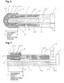
- the solid electrolyte element assumes the form of a closed-bottomed cylinder; the heater element disposed within the solid electrolyte element assumes a rod form; the central axis of the solid electrolyte element and the central axis of the heater element substantially coincide with each other; and at least a portion of an end of the heater element is in contact with the inner surface of a bottom portion of the solid electrolyte element.
- substantially coincide with each other means that the solid electrolyte element and the heater element are coaxial or that the central axes are separated from each other by not more than 500 ⁇ m (preferably, not more than 200 ⁇ m, more preferably 50 ⁇ m).
- the above disposition of the heater element expands a portion of the surface of the solid electrolyte element which is maintained at high temperature (preferably, 400-650°C, more preferably 450-600°C, further preferably 480-590°C). Further, there can be expanded the high-temperature portion of small temperature variations (the difference between the maximum and minimum temperatures falls within 100°C, more preferably within 80°C, further preferably within 50°C). That is, even when the detection electrode is formed, there can be reduced temperature dependence of the device for measuring combustible-gas concentration derived from temperature variations on the surface of the solid electrolyte element.
- the difference between average temperature as measured on the surface of the device at a position 1 mm from a bottom portion of the device toward a head portion of the device and average temperature as measured on the surface of the device at a position 5 mm from the bottom portion toward the head portion can be not greater than 50°C (preferably not greater than 40°C, more preferably not greater than 30°C).
- the device for measuring combustible-gas concentration has a maximum surface temperature of 400-650°C, variations in maximum temperature as measured at four locations which are 90 degrees apart from each other around the device can be suppressed to not greater than 60°C (preferably not greater than 50°C, further preferably 40°C).
- the surface of the device for measuring combustible-gas concentration means such a surface as observed after removal of a mounting shell of metal.
- the surface temperature of the device is the temperature of the surface of the diffusion layer when the diffusion layer is formed, or the temperature of the surface of the detection electrode or the solid electrolyte element when the diffusion layer is not formed.
- the detection electrode is formed at only the uniformly heated high-temperature portion.
- temperature distribution in the uniformly heated high-temperature portion is preferably uniform. Accordingly, preferably, as specified in the twelfth aspect of the invention, the central axis of the solid electrolyte element and the central axis of the heater element coincide or substantially coincide with each other. This feature establishes uniform temperature distribution on the surface of the uniformly heated high-temperature portion of the device for measuring combustible-gas concentration.
- an end portion of the heater element is in contact with the inner surface of a bottom portion of the solid electrolyte element, thereby expanding uniform temperature distribution up to the end of the bottom portion of the device for measuring combustible-gas concentration.
- an end portion of the heater element may be formed such that the diameter decreases toward the end of the heater element.
- the end portion of the heater element may be rounded as is the inner surface of the bottom portion of the solid electrolyte element.
- Such correction may be performed by, for example, the following methods: a portion of the solid electrolyte element of the device for measuring combustible-gas concentration is used as an oxygen sensor for measuring oxygen concentration; an oxygen sensor for measuring oxygen concentration is disposed separately from the device for measuring combustible-gas concentration; and a reference electrode and a detection electrode are formed so as to be exposed to the same gas to be measured, thereby directly obtaining sensor output after sensor output for oxygen concentration is cancelled.
- a device for measuring hydrocarbon-gas concentration, i.e. said combustible-gas is hydrocarbon-gas.
- hydrocarbon gas examples include hydrocarbons having 2-15 carbon atoms.
- the device of the present aspect of the invention for measuring hydrocarbon-gas concentration can sensitively detect hydrocarbons, particularly unsaturated hydrocarbons having 2-15 carbon atoms, and can accurately measure the concentration thereof.
- the detection electrode comprises gold and an oxide of one or more of the following elements: In, Fe, Ta, Ga, Sr, Eu, W, Ce, Ti, Zr, Sn and/or any transition metal. It is particularly advantageous that the metallic oxide comprises indium oxide and/or iron oxide.
- the invention also provides methods for measuring combustible-gas concentration or for measuring hydrocarbon-gas concentration, using a device according to one of the first through twelfth aspects of the invention or the further aspect of the invention, respectively, wherein the internal resistance of the solid electrolyte is measured periodically, and a voltage applied to the heater element is controlled such that the internal resistance becomes constant.
- propene and "propylene” are used synonymously. Propene is the more strictly correct term, whereas propylene is the term commonly used in this field.
- Fig. 1 is a diagram showing an example of an application of a device for measuring combustible-gas concentration or a device for measuring hydrocarbon-gas concentration.
- Fig. 2 is a diagram showing an example of an application of a device for measuring combustible-gas concentration or a device for measuring hydrocarbon-gas concentration.
- Fig. 3 is a diagram showing an example of an application of a device for measuring combustible-gas concentration or a device for measuring hydrocarbon-gas concentration.
- Fig. 4 is a schematic longitudinal sectional view of a device for measuring combustible-gas concentration or a device for measuring hydrocarbon-gas concentration, which device is equipped with a closed-bottomed solid electrolyte element.
- Fig. 5 is a schematic longitudinal sectional view of a device for measuring combustible-gas concentration or a device for measuring hydrocarbon-gas concentration, which device is equipped with a closed-bottomed solid electrolyte element.
- Fig. 6 is a schematic longitudinal sectional view of a device of the present invention for measuring combustible-gas concentration or a device of the present invention for measuring hydrocarbon-gas concentration, which device is equipped with a closed-bottomed solid electrolyte element.
- Fig. 7 is a schematic transverse sectional view of a laminate-type device for measuring combustible-gas concentration or a laminate-type device for measuring hydrocarbon-gas concentration.
- Fig. 8 is a schematic transverse sectional view of a laminate-type device for measuring combustible-gas concentration or a laminate-type device for measuring hydrocarbon-gas concentration.
- Fig. 9 is a schematic transverse sectional view of a device for measuring combustible-gas concentration or a device for measuring hydrocarbon-gas concentration, which device is equipped with oxygen concentration measurement means used for making correction for oxygen concentration.
- Fig. 10 is a schematic transverse sectional view of a laminate-type device for measuring combustible-gas concentration or a laminate-type device for measuring hydrocarbon-gas concentration.
- Fig. 11 is a graph showing relationship between offset and temperature within a solid electrolyte element.
- Fig. 12 is a graph showing relationship between oxygen concentration and sensor output.
- Fig. 13 is a graph showing relationship between sensor output and temperature of gas being measured.
- Fig. 14 is a graph showing relationship between a gas being measured and sensor output while gases being measured serve as parameters.
- Fig. 15 is a graph showing relationship between sensor output with use of temperature control means and sensor output without use of temperature control means.
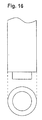
- Fig. 16 is a schematic view showing an end form of a heater element used in embodiments of the invention.
- Fig. 17 is a view of temperature distribution on an upper surface of a device H1 for measuring combustible-gas concentration.
- Fig. 18 is a view of temperature distribution on a right-hand side surface of the device H1 for measuring combustible-gas concentration.
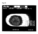
- Fig. 19 is a view of temperature distribution on a lower surface of the device H1 for measuring combustible-gas concentration.
- Fig. 20 is a view of temperature distribution on a left-hand side surface of the device H1 for measuring combustible-gas concentration.
- Fig. 21 is a view of temperature distribution on an upper surface of a device H2 for measuring combustible-gas concentration.
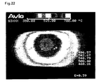
- Fig. 22 is a view of temperature distribution on a right-hand side surface of the device H2 for measuring combustible-gas concentration.
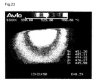
- Fig. 23 is a view of temperature distribution on a lower surface of the device H2 for measuring combustible-gas concentration.
- Fig. 24 is a view of temperature distribution on a left-hand side surface of the device H2 for measuring combustible-gas concentration. Reference Numerals are used to identify items shown in the drawings as follows:
- Yttria stabilized zirconia (hereinafter called merely YSZ) powder which contains 4.5 mol% Y 2 O 3 was filled into a rubber die, followed by being compacted.
- a detection electrode lead wire pattern was printed on the surface of each of the obtained green compacts by use of paste. Then, the green compacts were fired, thereby yielding closed-bottomed cylindrical solid electrolyte elements.
- the inner surface of each of the solid electrolyte elements was plated with platinum to thereby form a layer serving as a reference electrode.
- a layer serving as a first electrode layer was formed through platinum-plating.
- Gold powder (90 parts) and metallic-oxide powder (10 parts) were mixed.
- a binder, a dispersant, and butyl carbitol as solvent were added in respectively predetermined amounts.
- the obtained mixture was kneaded into paste.
- the paste was applied onto the platinum plating layer to thereby form a layer serving as a second electrode layer.
- the thus-prepared solid electrolyte elements were subjected to baking at a temperature of 880°C for 10 minutes.
- a diffusion layer which contained spinel was formed through thermal spraying on the surface of the detection layer of each of the solid electrolyte elements.
- a heater element was disposed in each of the solid electrolyte elements such that an end portion abutted an inner bottom portion of the solid electrolyte element.
- a reference electrode lead wire, a detection electrode lead wire, and heater element lead wires of each of the resultant solid electrolyte elements were connected to a temperature controller.
- device 1 the detection electrode contains only gold
- device 2 the detection electrode is formed of a single layer which contains gold and a metallic oxide
- device 3 the detection electrode is formed of two layers ⁇ the first electrode layer formed through platinum-plating and the second electrode layer which contains 90 parts of gold and 10 parts of indium oxide.
- Temperature dependence of offset was compared among the devices 1, 2, and 3. Measurement was carried out at room temperature in the atmosphere. While the heater element was electrically energized such that the internal resistance of the solid electrolyte element became 500 ⁇ , 1000 ⁇ , 1500 ⁇ , and 2000 ⁇ , offset and temperature within the solid electrolyte element were measured. The results are shown in FIG. 11.
- the devices 2 and 3 show a reduction in temperature dependence. Also, through employment of the detection electrode of the 2-layer structure, in which the first electrode layer contains a predominant amount of platinum, temperature dependence is greatly reduced.
- device 4 the detection electrode assumes a 2-layer structure ⁇ the first electrode layer formed through platinum-plating and the second electrode layer which contains only gold
- device 5 the detection electrode assumes a 2-layer structure ⁇ the first electrode layer formed through platinum-plating and the second electrode layer which contains 90 parts of gold and 10 parts of indium oxide
- device 6 the detection electrode assumes a 2-layer structure ⁇ the first electrode layer formed through platinum-plating and the second electrode layer which contains 90 parts of gold and 10 parts of iron oxide.
- the devices 4, 5, and 6 having different electrode components were compared in terms of oxygen concentration dependence.
- a gas to be measured contained propylene (500 ppmC as measured by an FID analyzer), CO 2 (10%), H 2 O (10%), O 2 (1, 7, or 15%), and N 2 (balance).
- the gas to be measured had a temperature of 300°C and flowed at 15 litres/min. While the oxygen concentration of the gas being measured was varied to 1%, 7%, or 15%, the heater was electrically energized such that the internal resistance of the solid electrolyte element become 1000 ⁇ (the surface temperature of the detection electrode became approximately 570°C). Sensor output was measured for each of the oxygen concentration values. The results are represented by the graph of FIG. 12.
- a metallic oxide contained in the detection electrode contributes greatly to a decrease in oxygen concentration dependence.
- sensor output exhibits a maximum variation of about 70 mV as a result of variations in oxygen concentration.
- variations in sensor output can be reduced to not greater than 20 mV, further to not greater than 10 mV.
- the paste was applied onto the platinum plating layer to thereby form a layer serving as a second electrode layer.
- the thus-prepared solid electrolyte elements were subjected to baking at a temperature of 880°C for 10 minutes. Subsequently, a diffusion layer was formed; a heater element was disposed; and a reference electrode lead wire, a detection electrode lead wire, and heater element lead wires of each of the resultant solid electrolyte elements were connected to a temperature controller.
- a temperature controller a temperature controller
- devices for measuring combustible-gas concentration in which the first electrode layer was not formed were manufactured while gold powders of three different grain sizes were used.
- sensitivity improves with the average grain size of gold powder.
- the devices for measuring combustible-gas concentration in which the first electrode layer is not formed as the grain size decreases, sensitivity improves.
- use of gold powder of a large grain size suppresses formation of a gold-platinum alloy, which does not generate or becomes unlikely to generate a mixed potential.
- devices 7 and 8 for measuring combustible-gas concentration which had been manufactured according to the method described in [1] such that the detection electrode assumes a 2-layer structure ⁇ the first electrode layer formed through platinum-plating and the second electrode layer which contains 90 parts of gold and 10 parts of indium oxide or 10 parts of iron oxide ⁇ and as well been manufactured in the following manner: device 7: the detection electrode is formed on the entire outer surface of the solid electrolyte element; and device 8: the detection electrode is formed on the outer surface of the solid electrolyte element at only a portion extending from an end portion of the solid electrolyte element to the vicinity of the interface between a heating resistor and a heating-resistor lead portion, which are formed within the heater element contained in the cylindrical solid electrolyte element.
- the detection electrode As seen from FIG. 13, through formation of the detection electrode on the outer surface of the solid electrolyte element at only a portion where high temperature is uniformly maintained, there can be suppressed variations in sensor output caused by the temperature of the gas being measured.
- Such formation of the detection electrode is particularly effective when the gas being measured contains a combustible gas (propylene) and has a temperature of not lower than 400°C.
- a device 9 for measuring combustible-gas concentration which had been manufactured according to the method described in [1] such that the detection electrode assumes a 2-layer structure ⁇ the first electrode layer formed through platinum-plating and the second electrode layer which contains 90 parts of gold and 10 parts of indium oxide.
- Sensor output from the device 9 was compared among combustible gases.
- This measurement used a gas to be measured which contained CO (10%), H 2 O (10%), O 2 (7%), and N 2 (balance) while the concentration of a combustible gas was varied as illustrated.
- the flow rate of the gas being measured was 15 litres/min, and the temperature of the gas being measured was 300°C.
- the results are plotted on the graph of FIG. 14, in which sensor output is plotted along the Y axis, and the concentration of a combustible gas contained in the gas being measured is plotted along the X axis.
- the device of the present invention for measuring combustible-gas concentration can sufficiently detect any combustible gas.
- the device can accurately measure the concentration of an unsaturated hydrocarbon having double bond, such as propylene, isobutene, or xylene and exhibits excellent response to such an unsaturated hydrocarbon.
- a device for measuring combustible-gas concentration in which a diffusion layer contains spinel was obtained in a manner similar to that described in [1].
- a solid electrolyte element on which electrodes and a diffusion layer were formed was obtained in a manner similar to that described in [1].
- the solid electrolyte element was dipped in platinic chloride (0.05 g/l) aqueous solution, followed by evacuation for 10 minutes. Subsequently, the solid electrolyte element was dried at a temperature of 100°C for at least 3 minutes, followed by firing at a temperature of 800°C for 1 hour in the atmosphere. Then, a heater element was disposed in the solid electrolyte element such that an end portion abutted an inner bottom portion of the solid electrolyte element.
- a reference electrode lead wire, a detection electrode lead wire, and heater element lead wires were connected to a temperature controller.
- a solid electrolyte element on which electrodes and a diffusion layer were formed was obtained in a manner similar to that described in [1].
- the solid electrolyte element was dipped in palladium nitrate (0.05 g/l) aqueous solution, followed by subjection to steps similar to those described above.
- the device for measuring combustible-gas concentration in which the diffusion layer contains neither platinum nor palladium the device for measuring combustible-gas concentration in which the diffusion layer contains platinum
- the device for measuring combustible-gas concentration in which the diffusion layer contains palladium the device for measuring combustible-gas concentration in which the diffusion layer contains palladium
- measurement was carried out while the heater element was electrically energized such that the solid electrolyte element maintained an internal resistance of 1000 ⁇ (a surface temperature of 570°C of the detection electrode).
- a gas to be measured contained propylene (1000 ppmC) or CO (1000 ppm), O 2 (7%), CO 2 (10%), H 2 O (10%), and N 2 (balance).
- the gas to be measured had a temperature of 300°C and flowed at 15 litres/min.
- the results are shown in Table 2.
- the device for measuring combustible-gas concentration in which the diffusion layer contains platinum decreases sensor output for CO by 84 mV or more as compared with the device for measuring combustible-gas concentration in which the diffusion layer does not contain platinum.
- sensor output for CO decreases. Conceivably, through combustion by platinum's catalysis, the amount of H 2 and CO which reaches the detection electrode has decreased. Sensor output for propylene also decreases. However, since a decrease in sensor output for propylene is small as compared with that for, particularly, CO, sensitivity for propylene relatively increases.
- the device for measuring combustible-gas concentration in which the diffusion layer contains palladium improves sensor output for propylene about 13% and decreases sensor output for CO about 20% as compared with the device for measuring combustible-gas concentration in which the diffusion layer does not contain palladium.
- the detection electrode contains 90 parts of gold and 10 parts of indium oxide
- sensor output with use of the temperature control means is compared with sensor output without use of the temperature control means.
- This measurement used a gas to be measured which contained O 2 (7%), CO 2 (10%), H 2 O (10%), and propylene (500 ppmC).
- the gas to be measured was tested for a temperature of 300°C and 500°C.
- the flow rate of the gas being measured was 15 litres/min.
- the internal resistance of the solid electrolyte element was controlled to 1000 ⁇ .
- voltage applied to the heater was maintained at 9 V. The results are shown in FIG. 15.
- sensor output with use of the temperature control means is 115.9 mV, whereas sensor output without use of the temperature control means is 21.8 mV, which is too small to sufficiently detect.
- a sensor output variation of about 130 mV is involved as a result of a temperature change in the gas being measured even when the concentration of propylene remains unchanged.
- a variation in sensor output derived from a variation in temperature can be suppressed to 10 mV.
- use of the temperature control means enables more sensitive detection and accurate measurement.
- a heater element having an end form shown in FIG. 1 A heater element having an end form shown in FIG.
- the heater element 16 was disposed in the following manner: in one device, the heater element was inserted into the solid electrolyte element such that the center axis thereof coincides with the center axis of the solid electrolyte element and such that the end of the heater element is in contact with the inner surface of the bottom portion of the solid electrolyte element (hereinafter, this device for measuring combustible-gas concentration is called "H1"); and in the other device, the heater element was obliquely inserted into the solid electrolyte element such that the end portion of the heater element abutted the inner side wall of the solid electrolyte element (hereinafter, this device for measuring combustible-gas concentration is called "H2").
- thermography the two kinds of devices for measuring combustible-gas concentration were measured for surface temperature at four locations which were 90 degrees apart from each other. The results are shown in FIGS. 17-24.
- a variation in temperature at point 3 is about 63°C or more.
- a variation in temperature is about 49°C.
- the maximum temperature on the surface of H2 is 548°C, whereas that of H1 is 562°C.
- the average value of temperatures measured at points 1-5 at all of the four locations is about 486°C in the case of H2, whereas the average temperature is as high as about 510°C in the case of H1.
- the range of a high-temperature portion is wide in H1 and is narrow in H2.
- the average temperature at point 1 is about 453°C; the average temperature at point 3 is about 514°C; and the difference in average temperature between points 1 and 3 is 61°C.
- the average temperature at point 1 is about 507°C; the average temperature at point 3 is about 542°C; and the difference in average temperature between points 1 and 3 is 35°C.
- the temperature difference between an end portion of the device for measuring combustible-gas concentration and a portion of the device which is heated most by the heating resistor is small, and the uniformly heated high-temperature portion is held at higher temperature and exhibits uniform temperature distribution.
- the gases to be measured had a temperature of 300°C and flowed at 15 litres/min.
- the results are shown in Table 3. Actual oxygen concentration 1% 7% 15% Corrected Sensor output (mV) 112.4 114.6 115.1 Calculated propene concentration (ppmC) 491.5 530 540.1 Uncorrected Sensor output (mV) 174.1 114.6 94.9 Calculated propene concentration (ppmC) 4240.7 530.8 266.7
- propylene concentration which is calculated on the assumption that oxygen concentration is fixed to 7% ranges from 266.7 ppmC to 4240.7 ppmC, indicating poor accuracy.
- propylene concentration which is calculated after sensor output is corrected for measured oxygen concentration ranges from 491 ppmC to 540 ppmC, indicating closeness to the actual propylene concentration.
- a heater pattern serving as a heating resistor was formed between two green sheets of alumina, thereby forming a substrate serving as a heater element.
- a reference electrode was formed on the substrate.
- Previously prepared paste which contained YSZ was applied onto the reference electrode, thereby forming a layer serving as a solid electrolyte element.
- a platinum layer serving as a first electrode and a platinum layer serving as an internal-resistance measurement electrode were printed on the applied paste serving as a solid electrolyte element, followed by firing for integration.
- a layer serving as a second electrode layer was formed on the first electrode layer through application of paste which had been prepared by the steps of: mixing 90 parts of gold powder and 10 parts of indium oxide powder; adding to the resultant powder mixture a binder, a dispersant, and butyl carbitol as solvent in respectively predetermined amounts; and kneading the resultant mixture.
- the resultant laminate was subjected to firing at 880°C for 10 minutes.
- a diffusion layer which contained spinel was formed through thermal spraying on the surface of the second electrode layer.
- a reference electrode lead wire, a detection electrode lead wire, and an internal-resistance measurement electrode lead wire were connected to temperature control means, thereby yielding a laminate-type device for measuring combustible-gas concentration.
- a device for measuring hydrocarbon-gas concentration was yielded.
- the device of the first aspect of the invention for measuring combustible-gas concentration can sensitively detect a combustible gas contained in a gas being measured and can accurately measure the concentration of the combustible gas, and as well can suppress dependence on the concentration of oxygen contained in the gas being measured to a very low level.
- the devices of the second and third aspects of the invention for measuring combustible-gas concentration can accurately carry out detection and measurement while suppressing offset to a low level and exhibiting low dependence on the temperature of a gas being measured.
- the device of the thirteenth aspect of the invention for measuring hydrocarbon-gas concentration can sensitively detect a hydrocarbon gas contained in a gas being measured and can accurately measure the concentration of the hydrocarbon gas, and as well can suppress dependence on the concentration of oxygen contained in the gas being measured to a very low level.
- the devices of the fourteenth and fifteenth aspects of the invention for measuring hydrocarbon-gas concentration can accurately carry out detection and measurement while suppressing offset to a low level and exhibiting low dependence on the temperature of a gas being measured.
- the method of the twenty-fifth aspect of the invention for measuring combustible-gas concentration and the method of the twenty-sixth aspect of the invention for measuring hydrocarbon-gas concentration can measure the concentration of a target gas in a particularly accurate manner.
Landscapes
- Chemical & Material Sciences (AREA)
- Life Sciences & Earth Sciences (AREA)
- Health & Medical Sciences (AREA)
- Pathology (AREA)
- General Physics & Mathematics (AREA)
- Immunology (AREA)
- Physics & Mathematics (AREA)
- Analytical Chemistry (AREA)
- Biochemistry (AREA)
- General Health & Medical Sciences (AREA)
- Chemical Kinetics & Catalysis (AREA)
- Electrochemistry (AREA)
- Molecular Biology (AREA)
- Engineering & Computer Science (AREA)
- Food Science & Technology (AREA)
- Medicinal Chemistry (AREA)
- Measuring Oxygen Concentration In Cells (AREA)
Applications Claiming Priority (4)
| Application Number | Priority Date | Filing Date | Title |
|---|---|---|---|
| JP16452099 | 1999-06-10 | ||
| JP16452099 | 1999-06-10 | ||
| JP21935199 | 1999-08-02 | ||
| JP21935199 | 1999-08-02 |
Publications (2)
| Publication Number | Publication Date |
|---|---|
| EP1059526A2 true EP1059526A2 (de) | 2000-12-13 |
| EP1059526A3 EP1059526A3 (de) | 2004-12-29 |
Family
ID=26489589
Family Applications (1)
| Application Number | Title | Priority Date | Filing Date |
|---|---|---|---|
| EP00304934A Withdrawn EP1059526A3 (de) | 1999-06-10 | 2000-06-09 | Methode und Gerät zur Messung der Konzentration brennbarer Gase in Abgasen |
Country Status (4)
| Country | Link |
|---|---|
| US (1) | US6533911B1 (de) |
| EP (1) | EP1059526A3 (de) |
| KR (1) | KR20010049489A (de) |
| CN (1) | CN1195982C (de) |
Cited By (3)
| Publication number | Priority date | Publication date | Assignee | Title |
|---|---|---|---|---|
| WO2003073092A1 (de) * | 2002-02-21 | 2003-09-04 | Robert Bosch Gmbh | Katalytisch aktive schicht und verfahren zur herstellung einer solchen |
| EP1293776A3 (de) * | 2001-09-11 | 2004-02-11 | NGK Spark Plug Company Limited | Einrichtung zur Überwachung der Ammoniakgaskonzentration |
| WO2014206648A1 (de) * | 2013-06-27 | 2014-12-31 | Robert Bosch Gmbh | Sensorelement zur erfassung mindestens einer eigenschaft eines messgases in einem messgasraum |
Families Citing this family (24)
| Publication number | Priority date | Publication date | Assignee | Title |
|---|---|---|---|---|
| AU5596700A (en) * | 1999-06-03 | 2000-12-28 | Charles H. CELLA | Contingency-based options and futures for contingent travel accommodations |
| JP4204773B2 (ja) * | 2001-09-17 | 2009-01-07 | 株式会社日立製作所 | 空燃比検出装置 |
| KR100987272B1 (ko) * | 2002-04-15 | 2010-10-12 | 이 아이 듀폰 디 네모아 앤드 캄파니 | 기체-감수성 재료의 감도, 속도 또는 안정성의 회복 방법 |
| JP4045549B2 (ja) * | 2004-02-12 | 2008-02-13 | 株式会社デンソー | 水素濃度検出装置及び水素濃度検出方法 |
| JP4895048B2 (ja) * | 2004-05-26 | 2012-03-14 | マイクロリン エルエルシー | NOxガスセンサーの方法及び装置 |
| US20080017510A1 (en) * | 2004-05-26 | 2008-01-24 | Nair Balakrishnan G | NOx Gas Sensor Method and Device |
| US20060151338A1 (en) * | 2005-01-12 | 2006-07-13 | Wang Da Y | Multi-function sensor system and method of operation |
| US20060231422A1 (en) * | 2005-04-14 | 2006-10-19 | Honeywell International Inc. | Switched gas sensor |
| US7611612B2 (en) * | 2005-07-14 | 2009-11-03 | Ceramatec, Inc. | Multilayer ceramic NOx gas sensor device |
| US7820028B2 (en) * | 2005-09-02 | 2010-10-26 | Honeywell International Inc. | Oxides of nitrogen gas sensors and methods |
| JP2009533682A (ja) * | 2006-04-14 | 2009-09-17 | セラマテック・インク | 呼気中の窒素酸化物を測定する装置および方法 |
| WO2008103311A2 (en) * | 2007-02-16 | 2008-08-28 | Ceramatec, Inc. | Nox sensor with improved selectivity and sensitivity |
| JP5119131B2 (ja) * | 2008-02-22 | 2013-01-16 | 日本特殊陶業株式会社 | アンモニアガスセンサ |
| US7975537B2 (en) * | 2008-04-25 | 2011-07-12 | Delphi Technologies, Inc. | Systems and methods for sensing an ammonia concentration in exhaust gases |
| JP5192031B2 (ja) * | 2010-12-27 | 2013-05-08 | 日本特殊陶業株式会社 | ガスセンサ |
| US9164080B2 (en) | 2012-06-11 | 2015-10-20 | Ohio State Innovation Foundation | System and method for sensing NO |
| DE102014201072A1 (de) * | 2013-02-01 | 2014-08-07 | Ford Global Technologies, Llc | Bestimmen eines Alterungsgrades eines Oxidationskatalysators |
| JP6194526B2 (ja) * | 2013-06-05 | 2017-09-13 | 高周波熱錬株式会社 | 板状ワークの加熱方法及び加熱装置並びにホットプレス成形方法 |
| CN104569038A (zh) * | 2013-10-11 | 2015-04-29 | 上海锦宜仪器有限公司 | 一种用于可燃气体检测装置及方法 |
| JP6321968B2 (ja) * | 2014-01-17 | 2018-05-09 | 株式会社Soken | ガスセンサ素子 |
| JP5883976B2 (ja) | 2014-07-29 | 2016-03-15 | 日本碍子株式会社 | ガスセンサの検知電極、導電性ペーストの製造方法、および、ガスセンサ |
| US10054575B2 (en) * | 2015-09-25 | 2018-08-21 | General Electric Company | Hydrogen detector and hydrogen detection method |
| JP6545627B2 (ja) * | 2016-02-19 | 2019-07-17 | 日本特殊陶業株式会社 | 温度センサ |
| CN110297032A (zh) * | 2019-07-15 | 2019-10-01 | 中国船舶重工集团公司第七一八研究所 | 一种基于固体电解质的电化学氢气传感器 |
Citations (4)
| Publication number | Priority date | Publication date | Assignee | Title |
|---|---|---|---|---|
| US4157282A (en) * | 1974-11-18 | 1979-06-05 | General Motors Corporation | Method for maintaining stoichiometric air/fuel mixtures |
| US4639305A (en) * | 1984-06-06 | 1987-01-27 | Ngk Insulators, Ltd. | Electrochemical element |
| DE3917710A1 (de) * | 1988-06-02 | 1990-01-04 | Ngk Insulators Ltd | Sauerstoffsensor mit eingebautem heizelement |
| US5520789A (en) * | 1993-12-27 | 1996-05-28 | Kabushiki Kaisha Toyota Chuo Kenkyusho | Gas sensor using ionic conductor |
Family Cites Families (16)
| Publication number | Priority date | Publication date | Assignee | Title |
|---|---|---|---|---|
| DE2304464C2 (de) | 1973-01-31 | 1983-03-10 | Robert Bosch Gmbh, 7000 Stuttgart | Meßfühler für die Überwachung der Funktionsfähigkeit von Katalysatoren in Abgas |
| JPS5033892A (de) * | 1973-07-24 | 1975-04-01 | ||
| JPS59100854A (ja) * | 1982-12-01 | 1984-06-11 | Mazda Motor Corp | 広域空燃比センサ− |
| JPS59175168U (ja) * | 1983-05-09 | 1984-11-22 | 日本碍子株式会社 | 加熱器付酸素濃度検出器 |
| JPH02126149A (ja) * | 1988-11-04 | 1990-05-15 | Fujikura Ltd | 耐腐食性ガス濃度センサ |
| DE4004172C2 (de) * | 1989-02-14 | 1998-06-04 | Ngk Spark Plug Co | Sauerstoffsensor zur Luft-Brennstoffgemisch-Kontrolle mit einer Schutzschicht, die eine Sauerstoff einschließende Substanz umfaßt, und Verfahren zur Herstellung des Sensors |
| DE4408504A1 (de) | 1994-03-14 | 1995-09-21 | Bosch Gmbh Robert | Sensor zur Bestimmung der Konzentration von Gaskomponenten in Gasgemischen |
| US5672811A (en) * | 1994-04-21 | 1997-09-30 | Ngk Insulators, Ltd. | Method of measuring a gas component and sensing device for measuring the gas component |
| US5472580A (en) * | 1994-06-09 | 1995-12-05 | General Motors Corporation | Catalytic converter diagnostic sensor |
| JP3684686B2 (ja) * | 1995-12-18 | 2005-08-17 | 株式会社デンソー | 酸素濃度判定装置 |
| US5762771A (en) * | 1996-02-06 | 1998-06-09 | Denso Corporation | Air-fuel ratio sensor |
| JP3027726B2 (ja) * | 1996-06-05 | 2000-04-04 | 日本特殊陶業株式会社 | ヒータ付き酸素センサ |
| FR2752057B1 (fr) | 1996-08-02 | 1998-12-04 | Bosch Gmbh Robert | Procede et dispositif servant a determiner la sensibilite d'un detecteur d'hydrocarbures pour moteur a combustion interne |
| JPH10239276A (ja) | 1996-12-27 | 1998-09-11 | Ngk Insulators Ltd | 一酸化炭素ガスセンサおよび同センサを用いた測定装置 |
| JP3372195B2 (ja) * | 1997-08-14 | 2003-01-27 | 日本特殊陶業株式会社 | NOxガス濃度検出器及び検出器に用いる電極の製造方法 |
| JP3874947B2 (ja) * | 1997-12-01 | 2007-01-31 | 日本碍子株式会社 | 二酸化硫黄ガスセンサ |
-
2000
- 2000-06-05 KR KR1020000030846A patent/KR20010049489A/ko not_active Withdrawn
- 2000-06-09 EP EP00304934A patent/EP1059526A3/de not_active Withdrawn
- 2000-06-09 CN CNB001080326A patent/CN1195982C/zh not_active Expired - Fee Related
- 2000-06-09 US US09/590,189 patent/US6533911B1/en not_active Expired - Lifetime
Patent Citations (4)
| Publication number | Priority date | Publication date | Assignee | Title |
|---|---|---|---|---|
| US4157282A (en) * | 1974-11-18 | 1979-06-05 | General Motors Corporation | Method for maintaining stoichiometric air/fuel mixtures |
| US4639305A (en) * | 1984-06-06 | 1987-01-27 | Ngk Insulators, Ltd. | Electrochemical element |
| DE3917710A1 (de) * | 1988-06-02 | 1990-01-04 | Ngk Insulators Ltd | Sauerstoffsensor mit eingebautem heizelement |
| US5520789A (en) * | 1993-12-27 | 1996-05-28 | Kabushiki Kaisha Toyota Chuo Kenkyusho | Gas sensor using ionic conductor |
Cited By (3)
| Publication number | Priority date | Publication date | Assignee | Title |
|---|---|---|---|---|
| EP1293776A3 (de) * | 2001-09-11 | 2004-02-11 | NGK Spark Plug Company Limited | Einrichtung zur Überwachung der Ammoniakgaskonzentration |
| WO2003073092A1 (de) * | 2002-02-21 | 2003-09-04 | Robert Bosch Gmbh | Katalytisch aktive schicht und verfahren zur herstellung einer solchen |
| WO2014206648A1 (de) * | 2013-06-27 | 2014-12-31 | Robert Bosch Gmbh | Sensorelement zur erfassung mindestens einer eigenschaft eines messgases in einem messgasraum |
Also Published As
| Publication number | Publication date |
|---|---|
| CN1195982C (zh) | 2005-04-06 |
| CN1277354A (zh) | 2000-12-20 |
| KR20010049489A (ko) | 2001-06-15 |
| US6533911B1 (en) | 2003-03-18 |
| EP1059526A3 (de) | 2004-12-29 |
Similar Documents
| Publication | Publication Date | Title |
|---|---|---|
| US6533911B1 (en) | Device for measuring combustible-gas concentration in an exhaust gas | |
| EP1077375B1 (de) | Verfahren und Vorrichtung zur Messung der Stickstoffoxidkonzentration | |
| EP1195601B1 (de) | Sauerstoffsensor und Methode zu dessen Herstellung | |
| EP0372425B1 (de) | Sauerstoffsensorelement und Vorrichtung zu dessen Herstellung | |
| EP1760461B1 (de) | Gassensor und Herstellungsverfahren dafür | |
| US6514397B2 (en) | Gas sensor | |
| EP1293776A2 (de) | Einrichtung zum Überwachen der Ammoniakgaskonzentration | |
| US10914696B2 (en) | Gas-sensor diagnosing method | |
| JPH0668480B2 (ja) | 酸素センサにおける電極構造 | |
| US10697926B2 (en) | Sensor material and gas sensor element and gas sensor derived therefrom | |
| JP3956435B2 (ja) | 酸素センサ素子 | |
| JP3443962B2 (ja) | 酸素濃度検出器およびその製造方法 | |
| JP5033017B2 (ja) | アンモニアガスセンサ | |
| JP4405643B2 (ja) | 可燃性ガス濃度測定装置 | |
| JP5281988B2 (ja) | アンモニアガスセンサ | |
| JP5479409B2 (ja) | アンモニアガスセンサ | |
| JP2589136B2 (ja) | 酸素センサ素子 | |
| US11255812B2 (en) | Gas sensor element, heater and gas sensor | |
| JP4402282B2 (ja) | 可燃性ガスセンサ素子の製造方法 | |
| JPH01213567A (ja) | 酸素検出素子 |
Legal Events
| Date | Code | Title | Description |
|---|---|---|---|
| PUAI | Public reference made under article 153(3) epc to a published international application that has entered the european phase |
Free format text: ORIGINAL CODE: 0009012 |
|
| AK | Designated contracting states |
Kind code of ref document: A2 Designated state(s): AT BE CH CY DE DK ES FI FR GB GR IE IT LI LU MC NL PT SE |
|
| AX | Request for extension of the european patent |
Free format text: AL;LT;LV;MK;RO;SI |
|
| RIC1 | Information provided on ipc code assigned before grant |
Ipc: 7G 01N 33/00 B Ipc: 7G 01N 27/406 B Ipc: 7G 01N 27/407 A |
|
| PUAL | Search report despatched |
Free format text: ORIGINAL CODE: 0009013 |
|
| AK | Designated contracting states |
Kind code of ref document: A3 Designated state(s): AT BE CH CY DE DK ES FI FR GB GR IE IT LI LU MC NL PT SE |
|
| AX | Request for extension of the european patent |
Extension state: AL LT LV MK RO SI |
|
| 17P | Request for examination filed |
Effective date: 20050627 |
|
| AKX | Designation fees paid |
Designated state(s): DE FR GB IT SE |
|
| STAA | Information on the status of an ep patent application or granted ep patent |
Free format text: STATUS: THE APPLICATION HAS BEEN WITHDRAWN |
|
| 18W | Application withdrawn |
Effective date: 20140819 |