EP1293776A2 - Einrichtung zum Überwachen der Ammoniakgaskonzentration - Google Patents
Einrichtung zum Überwachen der Ammoniakgaskonzentration Download PDFInfo
- Publication number
- EP1293776A2 EP1293776A2 EP02256274A EP02256274A EP1293776A2 EP 1293776 A2 EP1293776 A2 EP 1293776A2 EP 02256274 A EP02256274 A EP 02256274A EP 02256274 A EP02256274 A EP 02256274A EP 1293776 A2 EP1293776 A2 EP 1293776A2
- Authority
- EP
- European Patent Office
- Prior art keywords
- solid electrolyte
- electrolyte body
- gas
- detecting electrode
- electrode
- Prior art date
- Legal status (The legal status is an assumption and is not a legal conclusion. Google has not performed a legal analysis and makes no representation as to the accuracy of the status listed.)
- Withdrawn
Links
Images

Classifications
-
- G—PHYSICS
- G01—MEASURING; TESTING
- G01N—INVESTIGATING OR ANALYSING MATERIALS BY DETERMINING THEIR CHEMICAL OR PHYSICAL PROPERTIES
- G01N33/00—Investigating or analysing materials by specific methods not covered by groups G01N1/00 - G01N31/00
- G01N33/0004—Gaseous mixtures, e.g. polluted air
- G01N33/0009—General constructional details of gas analysers, e.g. portable test equipment
- G01N33/0027—General constructional details of gas analysers, e.g. portable test equipment concerning the detector
- G01N33/0036—General constructional details of gas analysers, e.g. portable test equipment concerning the detector specially adapted to detect a particular component
- G01N33/0054—Ammonia
-
- Y—GENERAL TAGGING OF NEW TECHNOLOGICAL DEVELOPMENTS; GENERAL TAGGING OF CROSS-SECTIONAL TECHNOLOGIES SPANNING OVER SEVERAL SECTIONS OF THE IPC; TECHNICAL SUBJECTS COVERED BY FORMER USPC CROSS-REFERENCE ART COLLECTIONS [XRACs] AND DIGESTS
- Y02—TECHNOLOGIES OR APPLICATIONS FOR MITIGATION OR ADAPTATION AGAINST CLIMATE CHANGE
- Y02A—TECHNOLOGIES FOR ADAPTATION TO CLIMATE CHANGE
- Y02A50/00—TECHNOLOGIES FOR ADAPTATION TO CLIMATE CHANGE in human health protection, e.g. against extreme weather
- Y02A50/20—Air quality improvement or preservation, e.g. vehicle emission control or emission reduction by using catalytic converters
Definitions
- the present invention relates to an apparatus for measuring the concentration of an ammonia gas, and more particularly to an apparatus for measuring the concentration of an ammonia gas, and capable of selectively measuring the concentration of an ammonia gas in an exhaust gas from an internal combustion engine.
- An exhaust gas from a diesel engine is short of components (CO, HC, etc.) for reducing NOx. Therefore, the introduction of a suitable reducing agent into the as yet unreduced exhaust gas is being discussed as a NOx reduction promoting method. Hydrocarbons are generally used as such reducing agents but, on the other hand, the use of urea is being discussed.
- the methods of reducing NOx by using urea include a method of catalytically reducing NOx by utilizing ammonia formed by hydrolyzing urea, and thereby decomposing the resultant product into innoxious N 2 and H 2 O.
- a method of catalytically reducing NOx by utilizing ammonia formed by hydrolyzing urea and thereby decomposing the resultant product into innoxious N 2 and H 2 O.
- JP-A-60-61654 which is adapted to detect the concentration of a component of an inflammable gas, such as ammonia, on the basis of an electromotive force occurring, in use, between a reference electrode and a detecting electrode which are formed on a surface of an oxygen ion conduction member.
- Inflammable gases such as CO, HC exist in an exhaust gas from a diesel engine.
- a related art gas concentration measuring apparatus has a high sensitivity with respect to inflammable gases other than an ammonia gas. Therefore, it was difficult to measure the concentration of an ammonia gas accurately with a related art gas concentration apparatus.
- an ammonia gas sensor using a zeolite film coated on a digital capacitor has been proposed for this use, a reliable one has not yet been developed.
- an apparatus capable of reliably and selectively detecting an ammonia gas, and speedily measuring the concentration thereof has not heretofore been available.
- the present invention has been made in view of the above-mentioned circumstances, and has an object to provide an ammonia gas concentration sensor capable of measuring the concentration of an ammonia gas speedily and accurately.
- the present invention also has an object to provide an ammonia gas sensor capable of detecting an ammonia gas selectively.
- the present invention provides in one aspect an apparatus for measuring the concentration of an ammonia gas, the apparatus comprising: a solid electrolyte body having an oxygen ion conductivity, a reference electrode formed on one surface of the solid electrolyte body for contacting a reference gas, a detecting electrode formed on the other surface of the solid electrolyte body and containing at least one of a noble metal and/or a metal oxide therein, and a Pd catalyst layer formed on an outer surface of the detecting electrode and including a Pd-containing porous body.
- the present invention further provides in another aspect an apparatus for measuring the concentration of an ammonia gas, the apparatus comprising: a solid electrolyte body having an oxygen ion conductivity, a reference electrode formed on one surface of the solid electrolyte body for contacting a reference gas, a detecting electrode formed on the other surface of the solid electrolyte body and containing at least one of a noble metal and/or metal oxide therein, and a Pd catalyst layer formed on an outer surface of the detecting electrode and including a porous body and Pd supported by said porous body.
- a best performance of selective ammonia detection in the measurement gas is attained when the detecting element formed on the oxygen ion-conducting solid electrolyte body is made of a mixture of Pt and Au and ZrO 2 , the porous body is made of porous spinel and the porous Pd is formed on the porous spinel.
- the metal oxide such as ZrO 2 , Al 2 O 3 and TiO 2 in the detecting electrode reduces interference with ammonia detection when the measurement gas contains oxygen.
- the detecting electrode be formed on only a portion of said other surface of the solid electrolyte body which corresponds to a heating resistor formed in the interior of the heater element.
- the solid electrolyte body has a closed cylindrical shape (i.e. tubular shape having a bottom), and the detecting electrode is formed on only a portion of an outer surface of the cylindrical solid electrolyte body, which detecting electrode extends from the position corresponding to the region of an interface between a heating resistor provided in the interior of the heater element that is disposed close to a closed end portion of the cylindrical solid electrolyte body.
- a temperature control unit adapted to control a voltage applied to the heater element on the basis of internal resistance of the solid electrolyte body, be provided.
- an internal resistance measuring electrode be provided which is formed on said one surface of the solid electrolyte body and in the vicinity of the heating resistor of the heater element so as to be separated from the reference electrode, and which is adapted to measure internal resistance of the solid electrolyte body, and that the temperature control unit be adapted to measure the internal resistance of the solid electrolyte body by the internal resistance measuring electrode and detecting electrode.
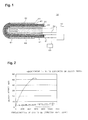
- an apparatus 10 for measuring the concentration of an ammonia gas is provided with a solid electrolyte body 30 having an oxygen ion conductivity, a reference electrode 20 formed on one surface of the solid electrolyte body and contacting a reference gas, a detecting electrode 40 formed on the other surface of the solid electrolyte body and containing a noble metal or a metal oxide therein, a Pd catalyst layer 50 formed on an outer surface of the detecting electrode and including a Pd-containing porous body, and a heater element 60.
- this apparatus it is possible to burn inflammable gases other than an ammonia gas on the Pd catalyst layer, selectively detect and measure the concentration of an ammonia gas, and improve the detecting and measuring accuracy.
- the apparatus 10 also includes a heater element 60, a temperature control unit 70 and a sensor output measuring unit 80.
- the reference electrode 20 is an electrode layer formed on an inner surface of the solid electrolyte body 30 including an inner bottom surface thereof, and made of a metal, such as Pt exposed to a reference gas.
- the reference electrode 20 is electrically connected to the temperature control unit 70 and sensor output measuring unit 80 via a reference electrode lead wire 21.
- the solid electrolyte body 30 is made of a material having oxygen ion conductivity, such as zirconia sinter and LaGaO 3 sinter, and which has a closed cylindrical form and includes a curved bottom surface.
- This solid electrolyte body is provided with the reference electrode 20 on an inner surface thereof including an inner bottom surface thereof, and detecting electrode 40 on an outer surface thereof including an outer bottom surface thereof.
- This solid electrolyte body is exposed to view at a portion thereof which is in the vicinity of an end surface thereof including that end surface.
- the detecting electrode 40 is an electrode layer formed on an outer surface of the solid electrolyte body 30 including an outer bottom surface thereof for exposure to a gas to be measured.
- This detecting electrode contains one or no less than two metals (especially, noble metals) and one or not smaller than two metal oxides therein, and is electrically connected to the temperature control unit 70 and sensor output measuring unit 80 via a detecting electrode lead wire 41.
- the Pd catalyst layer 50 is formed on an outer surface of the detecting electrode 40.
- the metals used in the detecting electrode 40 are Pt, Au, etc., and the metal oxides used are oxides, such as zirconia, alumina and titania.
- the Pd catalyst layer 50 is a catalyst layer supported on the detecting electrode 40 and in use is exposed to a gas to be measured; it is made of a Pd-supporting or a Pd-containing porous body.
- the Pd burns or oxidizes inflammable gases other than an ammonia gas.
- the porous body used in the Pd catalyst layer 50 meets the purpose as long as it is capable of allowing an inflammable gas, which is contained in a gas to be measured, to flow to the detecting electrode, and, for example, spinel or alumina and the like are used.
- the porous body is capable of maintaining at a substantially constant level a velocity of flow at its outer surface and a flow rate of the gas to be measured which flows from that surface to the detecting electrode, irrespective of the velocity of flow and flow rate of the same gas flowing on the mentioned surface. Accordingly, the porous body is capable of lowering the dependency of the gas to be measured upon the velocity of flow and flow rate of the gas.
- the porous body also acts both as a protective layer with respect to the poisoning of the detecting electrode and as a reinforcing layer and the like for increasing the strength thereof.
- the porous body may have two or more layers.
- the heater element 60 is an element for heating the solid electrolyte body 30, and maintains the temperature of the heated solid electrolyte body at a predetermined level.
- the heater element 60 has a heating resistor 61 buried in the portion thereof which is in the vicinity of a front end thereof, and a heating resistor lead wire 62 for supplying electric power to the heating resistor 61, and is electrically connected to the temperature control unit 70 via a heater element lead wire 63.
- the heater element 60 is of rod-like and flat plate-like shapes, and disposed so that the front end portion thereof contacts the interior of the closed cylindrical solid electrolyte body 30.
- the front end portion of the heater element 60 may have a curved surface similar to the inner bottom surface of the solid electrolyte body 30.
- the temperature control unit 70 is a device for controlling the temperature by regulating a voltage applied to the heater element on the basis of internal resistance of the solid electrolyte body 30, and includes a device for measuring the internal resistance of the solid electrolyte body 30, and a device for controlling a voltage applied to the heater element on the basis of this internal resistance.
- the methods of measuring the internal resistance of the solid electrolyte body 30 include a method of measuring the resistance between the reference electrode and detecting electrode, and a method of measuring resistance between an internal resistance measuring electrode, which is formed separately from the reference electrode, on an inner surface of the solid electrolyte body 30 and the detecting electrode.
- the temperature control unit 70 is electrically connected to each of the reference electrode 20, detecting electrode 40 and heater element 60 via lead wires 21, 41, 63. Owing to the provision of the temperature control unit 70, sharp detection and accurate measurement of the concentration of an object gas become possible.
- the sensor output measuring unit 80 is a unit for measuring a sensor output on the basis of a potential difference between the reference electrode 20 and detecting electrode 40, and is electrically connected to each of the reference electrode 20 and detecting electrode 40 via the lead wires 21, 41.
- each metal powder is mixed at a predetermined ratio (for example, 90 wt% of Pt and 10 wt% of Au), and a predetermined quantity of ZrO 2 is then added to the resultant mixture. Then ethylcellulose as a binder and butyl carbitol as a solvent are added to and mixed with the resultant product.
- detecting electrode paste can be obtained.
- the manufacturing of the closed cylindrical sensor element is done in the following manner.
- a powder of 4.5 mol% of Y 2 O 3 -containing yttria-stabilized zirconia (which will hereinafter be referred to simply as YSZ) is packed in a closed cylindrical rubber mold, and pressure molded.
- Paste forming the detecting electrode lead wire is then printed on an outer surface of the closed cylindrical molded body obtained, and the resultant product is calcined to obtain a closed cylindrical solid electrolyte body on which the detecting electrode lead wire is provided.
- the whole of an inner surface of the solid electrolyte body is then plated with platinum to form a reference electrode.
- the detecting electrode paste prepared in advance is then applied to a relative portion, and the resultant product is burnt in atmospheric air at 1400°C for 1 hour to form a detecting electrode.
- spinel is flame sprayed on an outer surface of the detecting electrode to form a porous layer.
- a sensor element on which the porous layer is formed is then immersed in a palladium nitrate solution of a predetermined concentration (0.01 to 0.2 mol/L), and the resultant product is dried, and then burned in atmospheric air at 800°C for 10 minutes, to form a porous Pd catalyst layer.
- a heater element is then set so that a front end portion thereof contacts an inner bottom surface of the solid electrolyte body.
- the reference electrode lead wire, detecting electrode lead wire and heater element lead wire are connected to the temperature control unit to obtain an apparatus for measuring the concentration of an ammonia gas.
- the apparatus for measuring the concentration of an ammonia gas according to the first embodiment is as shown in Fig. 1.
- the apparatus of a comparative example is as shown in Fig. 1 except that the catalyst layer is made of a non-Pd-containing porous body alone.
- the methods of manufacturing the apparatuses of the first embodiment and comparative example are identical with each other except the Pd-supporting step, and the sizes of these apparatuses are the same.
- Model gas units formed by imitating an exhaust gas unit in an actual vehicle were used, and a closed-end portion of the apparatus of the first embodiment or an apparatus of the comparative example was disposed in an intermediate portion of a flow passage.
- the temperature of the heater element in each apparatus was set to 600°C, and a gas to be measured (a base gas and a gas to be detected) containing one kind of gas to be detected (of a predetermined concentration) out of NH 3 , CO, C 3 H 6 was made to flow at 190°C and a flow rate of 15L/min.
- the sensor outputs during the tests were measured.
- a summary of the measuring conditions is shown in Table 1.
- each of the model gas units which is on the side of the reference electrode of the gas concentration measuring apparatus is exposed to the atmospheric air, and the portion which is on the side of the detecting electrode is exposed to the gas to be measured.
- the balance of N 2 in Table 1 means remaining gas composition occurring when one component of a gas to be measured is added to a base gas except N 2 .
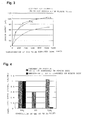
- Fig. 2 is a graph showing the correlation between a sensor output and the concentration of the gas to be detected in the apparatus according to the first embodiment of the present invention.
- Fig. 3 is a graph showing the correlation between a sensor output and the concentration of the gas to be detected in the apparatus according to the comparative example.
- Fig. 4 is a graph showing a sensitivity ratio of the gas to be detected to the ammonia gas in the apparatuses according to the first embodiment and comparative example.
- the sensor outputs with respect to CO and C 3 H 6 are held down to a level lower than 20 mV at all concentrations in the first embodiment in which Pd is supported on the porous body.
- the sensor output with respect to NH 3 somewhat lowers as compared with that in the comparative example, it increases with an increase in the gas concentration to a level higher than those with respect to CO and C 3 H 6 .
- the selectivity of NH 3 is improved noticeably owing to the supporting of Pd on the porous body.
- the same detecting electrode 40 as in the apparatus of the first embodiment is preferably provided only on the portion of an outer surface of a solid electrolyte body 30 that corresponds to a heating resistor 61 formed in the interior of a heater element 60, or, stated differently, only the portion of that outer surface that extends from the position corresponding to the neighborhood of an interface between the heating resistor 61 within the heater element 60 and a lead portion 62 of the heating resistor, to the position on that surface which corresponds to a front end portion of the solid electrolyte body.
- the reason is that, when the electrode is formed on only that portion of the outer surface of the solid electrolyte body which is maintained at a high, uniform and stable temperature, the dependency of the sensor output upon the temperature can be reduced.
- an internal resistance measuring electrode 90 separately from and independently of a reference electrode 20 and on the portion of an inner surface of the solid electrolyte 30 which is in the vicinity of the heating resistor.
- the internal resistance measuring electrode 90 and the detecting electrode 40 are electrically connected via internal resistance measuring lead wires 91 to the temperature control unit 70, and thereby measures the resistance between the internal resistance measuring electrode 90 and the detecting electrode 40, and a detecting electrode lead wire 41 and a reference electrode lead wire 21 are connected to only a sensor output measuring unit 80 and not to the temperature control unit 70.
- an ammonia gas contained in a gas to be measured can be detected selectively and sharply, and the concentration thereof can be measured speedily and accurately.
Landscapes
- Chemical & Material Sciences (AREA)
- Life Sciences & Earth Sciences (AREA)
- Engineering & Computer Science (AREA)
- Health & Medical Sciences (AREA)
- Analytical Chemistry (AREA)
- Food Science & Technology (AREA)
- Medicinal Chemistry (AREA)
- Physics & Mathematics (AREA)
- Combustion & Propulsion (AREA)
- Biochemistry (AREA)
- General Health & Medical Sciences (AREA)
- General Physics & Mathematics (AREA)
- Immunology (AREA)
- Pathology (AREA)
- Measuring Oxygen Concentration In Cells (AREA)
- Testing Of Engines (AREA)
Applications Claiming Priority (2)
| Application Number | Priority Date | Filing Date | Title |
|---|---|---|---|
| JP2001274675A JP2003083933A (ja) | 2001-09-11 | 2001-09-11 | アンモニアガス濃度測定装置 |
| JP2001274675 | 2001-09-11 |
Publications (2)
| Publication Number | Publication Date |
|---|---|
| EP1293776A2 true EP1293776A2 (de) | 2003-03-19 |
| EP1293776A3 EP1293776A3 (de) | 2004-02-11 |
Family
ID=19099670
Family Applications (1)
| Application Number | Title | Priority Date | Filing Date |
|---|---|---|---|
| EP02256274A Withdrawn EP1293776A3 (de) | 2001-09-11 | 2002-09-11 | Einrichtung zur Überwachung der Ammoniakgaskonzentration |
Country Status (3)
| Country | Link |
|---|---|
| US (1) | US20030062264A1 (de) |
| EP (1) | EP1293776A3 (de) |
| JP (1) | JP2003083933A (de) |
Cited By (1)
| Publication number | Priority date | Publication date | Assignee | Title |
|---|---|---|---|---|
| RU2477886C1 (ru) * | 2011-08-12 | 2013-03-20 | Государственное научное учреждение Северо-западный научно-исследовательский институт Механизации и электрификации сельского хозяйства Российской академии сельскохозяйственных наук (СЗ НИИМЭСХ Россельхозакадемии) | Способ определения и мониторинга величины массовых выбросов загрязняющих веществ в окружающую среду из животноводческого помещения и система для его осуществления |
Families Citing this family (26)
| Publication number | Priority date | Publication date | Assignee | Title |
|---|---|---|---|---|
| US7074319B2 (en) * | 2002-12-11 | 2006-07-11 | Delphi Technologies, Inc. | Ammonia gas sensors |
| US8257576B2 (en) * | 2002-12-11 | 2012-09-04 | Delphi Technologies, Inc. | Ammonia gas sensors with lanthanide vanadate sensing electrode |
| US8257575B2 (en) * | 2002-12-11 | 2012-09-04 | Delphi Technologies, Inc. | Ammonia gas sensors with vanadium-based sensing electrode |
| US20050155871A1 (en) * | 2004-01-15 | 2005-07-21 | Grant Robert B. | Electrochemical sensor |
| DE102004053460A1 (de) * | 2004-11-05 | 2006-05-11 | Emitec Gesellschaft Für Emissionstechnologie Mbh | Schutzelement für einen Messfühler, sowie entsprechender Messfühler und Wabenkörper |
| US7294252B2 (en) | 2005-10-07 | 2007-11-13 | Delphi Technologies, Inc. | NOx sensor and methods of using the same |
| EP2035824A2 (de) * | 2006-06-14 | 2009-03-18 | Ceramatec, Inc. | Ammoniakgassensor mit ungleichen elektroden |
| JP4874764B2 (ja) * | 2006-11-06 | 2012-02-15 | 日本特殊陶業株式会社 | アンモニアガスセンサ及びその製造方法 |
| DE102008032268B4 (de) * | 2007-07-11 | 2025-12-04 | Niterra Co., Ltd. | Ammoniakgassensor |
| JP5083898B2 (ja) * | 2007-07-11 | 2012-11-28 | 日本特殊陶業株式会社 | アンモニアガスセンサ |
| JP2009115776A (ja) * | 2007-07-11 | 2009-05-28 | Ngk Spark Plug Co Ltd | アンモニアガスセンサ |
| DE102008032331A1 (de) * | 2007-07-11 | 2009-01-15 | NGK Spark Plug Co., Ltd., Nagoya-shi | Ammoniakgassensor |
| JP5134399B2 (ja) * | 2007-11-08 | 2013-01-30 | 日本特殊陶業株式会社 | ガスセンサ及びガスセンサ制御装置 |
| JP5070082B2 (ja) * | 2008-02-22 | 2012-11-07 | 日本特殊陶業株式会社 | アンモニアガスセンサ |
| JP5070102B2 (ja) * | 2008-03-26 | 2012-11-07 | 日本特殊陶業株式会社 | アンモニアガスセンサ |
| JP5105284B2 (ja) * | 2008-03-27 | 2012-12-26 | 国立大学法人九州大学 | アンモニア濃度測定用センサ素子、アンモニア濃度測定装置、およびアンモニア濃度測定方法 |
| US7975537B2 (en) * | 2008-04-25 | 2011-07-12 | Delphi Technologies, Inc. | Systems and methods for sensing an ammonia concentration in exhaust gases |
| DE102008056791A1 (de) * | 2008-11-11 | 2010-05-12 | Volkswagen Ag | Sensorvorrichtung zum Messen einer Ammoniakkonzentration |
| JP5119212B2 (ja) * | 2009-07-01 | 2013-01-16 | 株式会社日本自動車部品総合研究所 | アンモニア濃度検出方法 |
| JP5271978B2 (ja) * | 2010-07-16 | 2013-08-21 | 日本特殊陶業株式会社 | アンモニアガスセンサ |
| JP5215500B2 (ja) * | 2012-11-13 | 2013-06-19 | 日本特殊陶業株式会社 | マルチガスセンサ及びガスセンサ制御装置 |
| CN104372350B (zh) * | 2013-08-15 | 2017-02-01 | 中国石油天然气股份有限公司 | 一种自动控温的长效参比电极 |
| EP3438653A4 (de) * | 2016-03-30 | 2019-11-27 | Cometnetwork Co., Ltd. | Sensor zur messung der stickoxidkonzentration und nachweis von ammoniakschlupf |
| JP6809355B2 (ja) * | 2017-04-18 | 2021-01-06 | 株式会社デンソー | ガスセンサ |
| JP7063168B2 (ja) * | 2018-07-27 | 2022-05-09 | 株式会社デンソー | ガスセンサ |
| JP6862400B2 (ja) * | 2018-10-30 | 2021-04-21 | 株式会社デンソー | アンモニア検出装置 |
Family Cites Families (8)
| Publication number | Priority date | Publication date | Assignee | Title |
|---|---|---|---|---|
| JPS5068187A (de) * | 1973-10-18 | 1975-06-07 | ||
| JPS5720655U (de) * | 1980-07-10 | 1982-02-02 | ||
| JPS5819553A (ja) * | 1981-07-27 | 1983-02-04 | Nippon Denso Co Ltd | 多機能酸素濃度検出器 |
| DE3610363A1 (de) * | 1986-03-27 | 1987-10-01 | Kernforschungsz Karlsruhe | Verfahren zum kontinuierlichen ueberwachen von konzentrationen von gasfoermigen bestandteilen in gasgemischen, ausgenommen o(pfeil abwaerts)2(pfeil abwaerts) |
| EP0668503A1 (de) * | 1994-02-17 | 1995-08-23 | General Motors Corporation | Katalytische Keramikoxyd-Mikrozusammensetzungen für die Verwendung als Vorgleichgewichtszone in Abgasdetektoren |
| JP3643224B2 (ja) * | 1997-11-25 | 2005-04-27 | 日本特殊陶業株式会社 | センサ素子電極形成方法 |
| JP4405643B2 (ja) * | 1999-06-10 | 2010-01-27 | 日本特殊陶業株式会社 | 可燃性ガス濃度測定装置 |
| KR20010049489A (ko) * | 1999-06-10 | 2001-06-15 | 오카무라 가네오 | 가연성 가스 농도측정장치 및 이것을 이용한 가연성 가스농도측정방법, 및 탄화수소가스 농도측정장치 및 이것을이용한 탄화수소가스 농도측정방법 |
-
2001
- 2001-09-11 JP JP2001274675A patent/JP2003083933A/ja active Pending
-
2002
- 2002-09-10 US US10/237,877 patent/US20030062264A1/en not_active Abandoned
- 2002-09-11 EP EP02256274A patent/EP1293776A3/de not_active Withdrawn
Cited By (1)
| Publication number | Priority date | Publication date | Assignee | Title |
|---|---|---|---|---|
| RU2477886C1 (ru) * | 2011-08-12 | 2013-03-20 | Государственное научное учреждение Северо-западный научно-исследовательский институт Механизации и электрификации сельского хозяйства Российской академии сельскохозяйственных наук (СЗ НИИМЭСХ Россельхозакадемии) | Способ определения и мониторинга величины массовых выбросов загрязняющих веществ в окружающую среду из животноводческого помещения и система для его осуществления |
Also Published As
| Publication number | Publication date |
|---|---|
| EP1293776A3 (de) | 2004-02-11 |
| US20030062264A1 (en) | 2003-04-03 |
| JP2003083933A (ja) | 2003-03-19 |
Similar Documents
| Publication | Publication Date | Title |
|---|---|---|
| EP1293776A2 (de) | Einrichtung zum Überwachen der Ammoniakgaskonzentration | |
| EP0257842B1 (de) | Elektrochemischer NOx-Sensor | |
| JP6824828B2 (ja) | アンモニア濃度測定装置,アンモニア濃度測定システム,排ガス処理システム,及びアンモニア濃度測定方法 | |
| EP3029290B1 (de) | Katalysatorverschleissdiagnosesystem und katalysatorverschleissdiagnoseverfahren | |
| EP3441586B1 (de) | Katalysatorverschleissdiagnoseverfahren | |
| EP0851226A2 (de) | Kohlenmonoxidsensor und Messvorrichtung unter Verwendung dieses Sensors | |
| EP3029292B1 (de) | Katalysatorverschleissdiagnoseverfahren | |
| US10488380B2 (en) | Apparatus for measuring ammonia concentration, system for measuring ammonia concentration, system for treating exhaust gas, and method for measuring ammonia concentration | |
| US6533911B1 (en) | Device for measuring combustible-gas concentration in an exhaust gas | |
| EP0903576A2 (de) | Gassensor | |
| US10697926B2 (en) | Sensor material and gas sensor element and gas sensor derived therefrom | |
| CN110161104B (zh) | 特定气体浓度测定装置以及特定气体浓度测定系统 | |
| US10480385B2 (en) | Apparatus for measuring combustible-gas concentration, system for measuring combustible-gas concentration, system for treating exhaust gas, method for measuring combustible-gas concentration, and method for deriving constant | |
| EP3258256A1 (de) | Material für die messelektrode eines nox-gassensors | |
| EP1004877B1 (de) | Gassensor, Methode zu dessen Herstellung und System unter Verwendung dieses Gassensors | |
| JP6867921B2 (ja) | アンモニア濃度測定装置,アンモニア濃度測定システム,排ガス処理システム,及びアンモニア濃度測定方法 | |
| JP5033017B2 (ja) | アンモニアガスセンサ | |
| JP2001141696A (ja) | ガス検出装置 | |
| EP0743431B1 (de) | Verfahren und Vorrichtung zum Feststellen der Verschlechterung eines Abgaskatalysators | |
| JP2001108649A (ja) | 可燃性ガス濃度測定装置及びこれを用いた可燃性ガス濃度測定方法並びに炭化水素ガス濃度測定装置及びこれを用いた炭化水素ガス濃度測定方法 | |
| JP2003518619A (ja) | ガス成分を測定するためのガスセンサーのセンサー素子 | |
| US10329988B2 (en) | Apparatus for measuring ammonia concentration, system for measuring ammonia concentration, system for treating exhaust gas, and method for measuring ammonia concentration | |
| JP7152210B2 (ja) | 測定用対応関係導出方法,特定ガス濃度測定装置の製造方法,及び特定ガス濃度測定装置 | |
| CN112601954A (zh) | 用于测量氮氧化物的方法和用于执行该方法的装置 | |
| JPH11237366A (ja) | ガスセンサ |
Legal Events
| Date | Code | Title | Description |
|---|---|---|---|
| PUAI | Public reference made under article 153(3) epc to a published international application that has entered the european phase |
Free format text: ORIGINAL CODE: 0009012 |
|
| AK | Designated contracting states |
Kind code of ref document: A2 Designated state(s): AT BE BG CH CY CZ DE DK EE ES FI FR GB GR IE IT LI LU MC NL PT SE SK TR Designated state(s): AT BE BG CH CY CZ DE DK EE ES FI FR GB GR IE IT LI LU MC NL PT SE SK TR |
|
| AX | Request for extension of the european patent |
Extension state: AL LT LV MK RO SI |
|
| PUAL | Search report despatched |
Free format text: ORIGINAL CODE: 0009013 |
|
| AK | Designated contracting states |
Kind code of ref document: A3 Designated state(s): AT BE BG CH CY CZ DE DK EE ES FI FR GB GR IE IT LI LU MC NL PT SE SK TR |
|
| AX | Request for extension of the european patent |
Extension state: AL LT LV MK RO SI |
|
| AKX | Designation fees paid | ||
| REG | Reference to a national code |
Ref country code: DE Ref legal event code: 8566 |
|
| STAA | Information on the status of an ep patent application or granted ep patent |
Free format text: STATUS: THE APPLICATION IS DEEMED TO BE WITHDRAWN |
|
| 18D | Application deemed to be withdrawn |
Effective date: 20040812 |