EP1059898B1 - Beinprothese und steuerung dafür - Google Patents
Beinprothese und steuerung dafür Download PDFInfo
- Publication number
- EP1059898B1 EP1059898B1 EP99937863A EP99937863A EP1059898B1 EP 1059898 B1 EP1059898 B1 EP 1059898B1 EP 99937863 A EP99937863 A EP 99937863A EP 99937863 A EP99937863 A EP 99937863A EP 1059898 B1 EP1059898 B1 EP 1059898B1
- Authority
- EP
- European Patent Office
- Prior art keywords
- variability
- locomotion
- control device
- parameter
- prosthesis
- Prior art date
- Legal status (The legal status is an assumption and is not a legal conclusion. Google has not performed a legal analysis and makes no representation as to the accuracy of the status listed.)
- Expired - Lifetime
Links
- 210000003141 lower extremity Anatomy 0.000 title claims abstract description 14
- 230000033001 locomotion Effects 0.000 claims abstract description 57
- 210000003127 knee Anatomy 0.000 claims abstract description 17
- 210000000629 knee joint Anatomy 0.000 claims abstract description 14
- 230000004044 response Effects 0.000 claims abstract description 10
- 238000005259 measurement Methods 0.000 claims description 14
- 238000000034 method Methods 0.000 claims description 13
- 238000013016 damping Methods 0.000 claims description 2
- 238000012804 iterative process Methods 0.000 claims description 2
- 210000001364 upper extremity Anatomy 0.000 claims 1
- 230000005021 gait Effects 0.000 description 7
- 230000008569 process Effects 0.000 description 7
- 210000000689 upper leg Anatomy 0.000 description 5
- 210000003414 extremity Anatomy 0.000 description 4
- 230000000694 effects Effects 0.000 description 3
- 230000009471 action Effects 0.000 description 2
- 230000009467 reduction Effects 0.000 description 2
- OKTJSMMVPCPJKN-UHFFFAOYSA-N Carbon Chemical compound [C] OKTJSMMVPCPJKN-UHFFFAOYSA-N 0.000 description 1
- 229920002430 Fibre-reinforced plastic Polymers 0.000 description 1
- 230000006978 adaptation Effects 0.000 description 1
- 230000003044 adaptive effect Effects 0.000 description 1
- 238000005452 bending Methods 0.000 description 1
- 229910052799 carbon Inorganic materials 0.000 description 1
- 230000009194 climbing Effects 0.000 description 1
- 238000000205 computational method Methods 0.000 description 1
- 230000008878 coupling Effects 0.000 description 1
- 238000010168 coupling process Methods 0.000 description 1
- 238000005859 coupling reaction Methods 0.000 description 1
- 230000003247 decreasing effect Effects 0.000 description 1
- 238000001514 detection method Methods 0.000 description 1
- 238000010586 diagram Methods 0.000 description 1
- 238000011156 evaluation Methods 0.000 description 1
- 239000011151 fibre-reinforced plastic Substances 0.000 description 1
Images

Classifications
-
- A—HUMAN NECESSITIES
- A61—MEDICAL OR VETERINARY SCIENCE; HYGIENE
- A61F—FILTERS IMPLANTABLE INTO BLOOD VESSELS; PROSTHESES; DEVICES PROVIDING PATENCY TO, OR PREVENTING COLLAPSING OF, TUBULAR STRUCTURES OF THE BODY, e.g. STENTS; ORTHOPAEDIC, NURSING OR CONTRACEPTIVE DEVICES; FOMENTATION; TREATMENT OR PROTECTION OF EYES OR EARS; BANDAGES, DRESSINGS OR ABSORBENT PADS; FIRST-AID KITS
- A61F2/00—Filters implantable into blood vessels; Prostheses, i.e. artificial substitutes or replacements for parts of the body; Appliances for connecting them with the body; Devices providing patency to, or preventing collapsing of, tubular structures of the body, e.g. stents
- A61F2/50—Prostheses not implantable in the body
- A61F2/68—Operating or control means
- A61F2/70—Operating or control means electrical
-
- A—HUMAN NECESSITIES
- A61—MEDICAL OR VETERINARY SCIENCE; HYGIENE
- A61F—FILTERS IMPLANTABLE INTO BLOOD VESSELS; PROSTHESES; DEVICES PROVIDING PATENCY TO, OR PREVENTING COLLAPSING OF, TUBULAR STRUCTURES OF THE BODY, e.g. STENTS; ORTHOPAEDIC, NURSING OR CONTRACEPTIVE DEVICES; FOMENTATION; TREATMENT OR PROTECTION OF EYES OR EARS; BANDAGES, DRESSINGS OR ABSORBENT PADS; FIRST-AID KITS
- A61F2/00—Filters implantable into blood vessels; Prostheses, i.e. artificial substitutes or replacements for parts of the body; Appliances for connecting them with the body; Devices providing patency to, or preventing collapsing of, tubular structures of the body, e.g. stents
- A61F2/50—Prostheses not implantable in the body
- A61F2/60—Artificial legs or feet or parts thereof
- A61F2/64—Knee joints
-
- A—HUMAN NECESSITIES
- A61—MEDICAL OR VETERINARY SCIENCE; HYGIENE
- A61F—FILTERS IMPLANTABLE INTO BLOOD VESSELS; PROSTHESES; DEVICES PROVIDING PATENCY TO, OR PREVENTING COLLAPSING OF, TUBULAR STRUCTURES OF THE BODY, e.g. STENTS; ORTHOPAEDIC, NURSING OR CONTRACEPTIVE DEVICES; FOMENTATION; TREATMENT OR PROTECTION OF EYES OR EARS; BANDAGES, DRESSINGS OR ABSORBENT PADS; FIRST-AID KITS
- A61F2/00—Filters implantable into blood vessels; Prostheses, i.e. artificial substitutes or replacements for parts of the body; Appliances for connecting them with the body; Devices providing patency to, or preventing collapsing of, tubular structures of the body, e.g. stents
- A61F2/50—Prostheses not implantable in the body
- A61F2/68—Operating or control means
- A61F2/74—Operating or control means fluid, i.e. hydraulic or pneumatic
-
- A—HUMAN NECESSITIES
- A61—MEDICAL OR VETERINARY SCIENCE; HYGIENE
- A61F—FILTERS IMPLANTABLE INTO BLOOD VESSELS; PROSTHESES; DEVICES PROVIDING PATENCY TO, OR PREVENTING COLLAPSING OF, TUBULAR STRUCTURES OF THE BODY, e.g. STENTS; ORTHOPAEDIC, NURSING OR CONTRACEPTIVE DEVICES; FOMENTATION; TREATMENT OR PROTECTION OF EYES OR EARS; BANDAGES, DRESSINGS OR ABSORBENT PADS; FIRST-AID KITS
- A61F2/00—Filters implantable into blood vessels; Prostheses, i.e. artificial substitutes or replacements for parts of the body; Appliances for connecting them with the body; Devices providing patency to, or preventing collapsing of, tubular structures of the body, e.g. stents
- A61F2/50—Prostheses not implantable in the body
- A61F2/78—Means for protecting prostheses or for attaching them to the body, e.g. bandages, harnesses, straps, or stockings for the limb stump
- A61F2/80—Sockets, e.g. of suction type
-
- A—HUMAN NECESSITIES
- A61—MEDICAL OR VETERINARY SCIENCE; HYGIENE
- A61F—FILTERS IMPLANTABLE INTO BLOOD VESSELS; PROSTHESES; DEVICES PROVIDING PATENCY TO, OR PREVENTING COLLAPSING OF, TUBULAR STRUCTURES OF THE BODY, e.g. STENTS; ORTHOPAEDIC, NURSING OR CONTRACEPTIVE DEVICES; FOMENTATION; TREATMENT OR PROTECTION OF EYES OR EARS; BANDAGES, DRESSINGS OR ABSORBENT PADS; FIRST-AID KITS
- A61F2/00—Filters implantable into blood vessels; Prostheses, i.e. artificial substitutes or replacements for parts of the body; Appliances for connecting them with the body; Devices providing patency to, or preventing collapsing of, tubular structures of the body, e.g. stents
- A61F2/50—Prostheses not implantable in the body
- A61F2002/5003—Prostheses not implantable in the body having damping means, e.g. shock absorbers
-
- A—HUMAN NECESSITIES
- A61—MEDICAL OR VETERINARY SCIENCE; HYGIENE
- A61F—FILTERS IMPLANTABLE INTO BLOOD VESSELS; PROSTHESES; DEVICES PROVIDING PATENCY TO, OR PREVENTING COLLAPSING OF, TUBULAR STRUCTURES OF THE BODY, e.g. STENTS; ORTHOPAEDIC, NURSING OR CONTRACEPTIVE DEVICES; FOMENTATION; TREATMENT OR PROTECTION OF EYES OR EARS; BANDAGES, DRESSINGS OR ABSORBENT PADS; FIRST-AID KITS
- A61F2/00—Filters implantable into blood vessels; Prostheses, i.e. artificial substitutes or replacements for parts of the body; Appliances for connecting them with the body; Devices providing patency to, or preventing collapsing of, tubular structures of the body, e.g. stents
- A61F2/50—Prostheses not implantable in the body
- A61F2/60—Artificial legs or feet or parts thereof
- A61F2002/607—Lower legs
-
- A—HUMAN NECESSITIES
- A61—MEDICAL OR VETERINARY SCIENCE; HYGIENE
- A61F—FILTERS IMPLANTABLE INTO BLOOD VESSELS; PROSTHESES; DEVICES PROVIDING PATENCY TO, OR PREVENTING COLLAPSING OF, TUBULAR STRUCTURES OF THE BODY, e.g. STENTS; ORTHOPAEDIC, NURSING OR CONTRACEPTIVE DEVICES; FOMENTATION; TREATMENT OR PROTECTION OF EYES OR EARS; BANDAGES, DRESSINGS OR ABSORBENT PADS; FIRST-AID KITS
- A61F2/00—Filters implantable into blood vessels; Prostheses, i.e. artificial substitutes or replacements for parts of the body; Appliances for connecting them with the body; Devices providing patency to, or preventing collapsing of, tubular structures of the body, e.g. stents
- A61F2/50—Prostheses not implantable in the body
- A61F2/68—Operating or control means
- A61F2/70—Operating or control means electrical
- A61F2002/704—Operating or control means electrical computer-controlled, e.g. robotic control
-
- A—HUMAN NECESSITIES
- A61—MEDICAL OR VETERINARY SCIENCE; HYGIENE
- A61F—FILTERS IMPLANTABLE INTO BLOOD VESSELS; PROSTHESES; DEVICES PROVIDING PATENCY TO, OR PREVENTING COLLAPSING OF, TUBULAR STRUCTURES OF THE BODY, e.g. STENTS; ORTHOPAEDIC, NURSING OR CONTRACEPTIVE DEVICES; FOMENTATION; TREATMENT OR PROTECTION OF EYES OR EARS; BANDAGES, DRESSINGS OR ABSORBENT PADS; FIRST-AID KITS
- A61F2/00—Filters implantable into blood vessels; Prostheses, i.e. artificial substitutes or replacements for parts of the body; Appliances for connecting them with the body; Devices providing patency to, or preventing collapsing of, tubular structures of the body, e.g. stents
- A61F2/50—Prostheses not implantable in the body
- A61F2/68—Operating or control means
- A61F2/70—Operating or control means electrical
- A61F2002/705—Electromagnetic data transfer
Definitions
- This invention relates to a lower limb prosthesis including a dynamically adjustable joint movement control unit arranged to control either or both of flexion and extension of the joint automatically.
- a pneumatic piston and cylinder device coupled between the thigh part and the shin part has a motor-driven valve which alters the resistance of the device to movement at the knee joint in response to command signals from an electronic control circuit deriving input signals from a transducer mounted on the control device, the repetition rate of the input signals being representative of the speed of locomotion, particularly the step period during walking.
- the control circuit includes a radio receiver for receiving command signals from a remote control transmitter operated by a prosthetist, a processor for processing the command signals and the transducer signals, and a memory for storing a map of valve settings against locomotion speed ranges.
- the processor has a teaching mode whereby the amputee is asked to walk at a particular speed and the system is "taught" by the prosthetist inasmuch as the prosthetist causes the valve to be adjusted under remote control in real time while the amputee is walking until the best gait is obtained. The same process is performed at different walking speeds and the prosthetist selects a valve setting for each speed which, in his or her opinion, appears to produce the best walking gait. These valve settings are stored at the end of a teaching session. In a playback mode of the processor, signals corresponding to the stored valve settings are fed to the motor-driven valve automatically according to the speed at which the amputee walks.
- the above system has yielded notable improvements in gait for above-knee amputees due to its adaptation of resistance to knee joint movement to different settings suiting different walking speeds rather than relying on a fixed resistance setting for all walking speeds. These improvements have been achieved without requiring excessively lengthy sessions with the prosthetist.
- EP-A-0549855 (James, Kelvin B.) relates to an above knee prosthesis employing an hydraulic damper to regulate the angular velocity of rotation of the artificial knee joint passively.
- a programmed microprocessor recognises common gait patterns from information received from strain and knee angle sensors on the prosthesis. The influence of the damper on flexion and extension of the knee joint is adjusted in response to the information received from the sensors, in particular sensing signals from the sensors which continuously determine the state of the prosthesis during segments of each step period. By comparing the received signals with a set of stored threshold values, control means act to vary the damping of the knee joint with the aim of simulating a so-called "natural knee action".
- a lower limb prosthesis for an above-knee amputee including a dynamically adjustable knee movement control unit (18, 20, 22, 24A, 24B) arranged to control flexion and/or extension of a knee joint (10) of the prosthesis characterised in that the control unit is arranged to control flexion and/or extension of the joint automatically in response to the sensed step-to-step variability of at least one kinetic or kinematic parameter of locomotion in order to reduce the said step-to-step variability.
- a self-learning adaptive control system for a lower limb prosthesis, the system measuring the step-to-step variation of one or more parameters associated with the dynamic operation of the limb, and automatically processing the variation measurement to optimise or reduce the step-to-step variability of the parameter, preferably using an iterative process, in order to achieve an optimum locomotion characteristic.
- the knee movement control unit is a piston and cylinder assembly having an electrically adjustable valve responsive to an adjusting signal generated by a microprocessor which is programmed to derive a kinematic parameter variability value from input signals produced by a transducer mounted on the limb.
- the kinematic parameter may be the amplitude of the flexion angle of the joint which, in the case of flexion and/or extension of the joint being controlled by a piston and cylinder device connected between a thigh part and a shin part of the prosthesis, may be represented by the amplitude or magnitude of the piston stroke.
- the duration of the flexed state e.g. the time interval from commencement of the flexion movement to termination of the extension movement, these points typically being determined by setting angular thresholds or piston positional thresholds
- stride length may be used as a kinematic parameter.
- the sensed variability is an electrical signal value representative of the degree of variation of a kinematic parameter measured during each of a plurality of steps taken by the amputee during locomotion, the parameter being measured during each step taken by the amputee which is within a predetermined range of locomotion, such as a particular walking speed range or a particular category of locomotion.
- range of locomotion means different modes of locomotion such as walking on a level surface, walking down an incline, walking up an incline, walking down stairs, climbing up stairs, or running.
- Speeds of walking or running as speed ranges may be determined by measuring the repetition rate or the average step period of a walking or running cycle, each cycle extending, for instance, from heel contact to heel contact through stance phase and swing phase.
- the control system may be configured to determine the variability of one or more kinetic or kinematic parameters over each of a plurality of the ranges of locomotion so that the control unit is adjusted to a plurality of optimum settings for the different respective locomotion ranges. It is possible, then, for the system to determine the range of locomotion from received electrical signals from one or more transducers forming part of the prosthesis, and, using the same signals, to perform an iterative variability measurement and adjustment process within each respective locomotion range. The process minimises variability of the selected parameter or, in the case of the variability a plurality of parameters being measured, minimises the variability of at least one of them (which is designated the primary parameter). Generally, altering or minimising the variability of a kinematic parameter is associated with altering or minimising an underlying kinetic parameter of locomotion.
- the control unit typically includes a knee movement control device, a transducer for generating a sensing signal related to a kinematic parameter of locomotion, and an electronic control circuit having an input coupled to the transducer and an output coupled to the control device, wherein the transducer and the control circuit are configured to determine the step-to-step variability of the kinematic parameter and to generate output signals for adjusting the control device thereby to reduce the variability of the kinematic parameter and to generate output signals for adjusting the control device thereby to reduce the step-to-step variability of the parameter so as to obtain an optimum setting of the control device.
- control circuit is configured to record a value of the kinematic parameter during each of a plurality of locomotion cycles, to compare the recorded values to a establish a variability measurement, to compare the variability measurement with a reference variability value and, if the variability measurement exceeds the reference value, to initiate a control device adjustment procedure in which the control device is dynamically adjusted so as substantially to minimise the variability of the or each parameter.
- the preferred control system measures the speed of walking, computes the variation of a kinematic parameter over a number of steps, processes the measured parameter data in order to determine whether the degree of variation falls within a band of optimum parameter variation, adjusts the resistance to joint flexion and/or extension by a predetermined increment in accordance with the degree of variation of the parameter or parameters in order to reduce the amount of variability.
- the corresponding control device settings, in conjunction with walking speed values, can be stored in order that, in a playback mode, the control device is adjusted to a variability-minimising setting corresponding to a measured walking speed as determined by the stored relationships.
- the optimisation process may be carried out continuously during use of the prosthesis, variation of the kinematic parameters being iteratively reduced whenever the variability deviates from a predetermined optimum condition.
- the speed of walking may be defined according to a number of non-overlapping speed ranges which might be designated “slow”, “medium”, and “fast”, the stored data associating a limb control device setting for each range which has been determined by means of the automatic self-learning process as yielding substantially the minimum variation in the kinematic parameter or parameters.
- a control system for a lower limb prosthesis comprises an input for connection to a transducer on the prosthesis which produces an electrical transducer signal in response to flexion or extension of a joint an output for connection to the control device for influencing the operation of the joint during locomotion, and a processor circuit arranged to compute, from the transducer signal received at the input, a variability value indicative of the variability of a kinematic parameter of locomotion from step to step, and, automatically in response to the said variability value fulfilling a predetermined condition or conditions, to produce an output signal causing the control device to be adjusted in a manner such as to reduce the variability of the said parameter.
- FIG. 1 A lower limb prosthesis in accordance with the invention is shown in Figure 1.
- the prosthesis has a knee joint 10 with a knee pivot 12 connecting a thigh component 14 to a shin component 16.
- the thigh component comprises a knee chassis 14A, an alignment device 14B, and a stump socket 14C.
- the shin component 16 has a conventional carbon fibre reinforced plastics shin cradle 16A which houses a piston and cylinder assembly 18 acting as a flexion control device to form part of a control system.
- the assembly 18 comprises a cylinder 18A which is pivotally coupled to the posterior part of the shin cradle 16A, and a piston 18B having a piston rod 18C which is pivotally coupled to the knee chassis 14A.
- the piston and cylinder assembly 18 is a pneumatic device, the resistance to flexion of the knee joint being controlled by a needle valve 18D which is adjustable by an electrical stepper motor 20 and an associated screw-threaded shaft 20A connected to the needle member of the needle valve.
- a d.c. motor may be used as an alternative to a stepper motor.
- the needle valve 18D lies in a passage 18E in the body of the cylinder 18A, the passage 18E interconnecting the cylinder interior spaces 18F, 18G on opposite sides of the piston 18C and emerging at a port 18H in the wall of the cylinder. Operation of the motor 20 causes the shaft 20A to move axially so that the needle member moves into or out of a passageway forming part of passage 18E.
- the passage 18E constitutes a first bypass passage interconnecting the cylinder spaces on opposite sides of the piston 18C.
- a second bypass passage 18I incorporating a valve such as a one-way valve 18J is formed in the piston 18C so that the needle valve 18D is effective only on one stroke of the piston, in this case the stroke corresponding to increasing flexion of the knee joint 10.
- the one-way valve 18J may be arranged so as not to close-off the second bypass passage 18I completely on the increasing flexion stroke, but rather merely to reduce the orifice area through the piston 18C.
- Such an arrangement has the effect of the needle valve 18D determining the resistance to motion of the piston 18C in both directions, i.e. for increasing and decreasing flexion, but with the effect of variations in the orifice area of the needle valve 18D being greater in one direction than the other, depending on the direction of operation of the valve 18J.
- stepper motor 20 and its threaded shaft 20A are mounted in the body of the cylinder 18, preferably adjacent the pivotal coupling 21 of the cylinder 18 to the shin 16.
- the stepper motor is driven by a microcomputer which forms part of an electronic circuit assembly 22 and is part of the control system.
- the microcomputer determines knee flexion and extension movements by means of a magnetic proximity sensor comprising a first part, preferably a transducer 24A, mounted in or associated with the cylinder body 18A, and a second part, preferably a permanent magnet 24B, mounted on or associated with the piston 18B.
- transducer 24A may be mounted on a printed circuit board constituting the electronic circuit assembly 22 which is, in turn, associated with cylinder 18.
- the electronic circuit assembly 22 and the stepper motor 20 are powered by batteries, one of which is shown in Figure 1 and indicated by the reference 26.
- the electronic circuit assembly 22 is shown in more detail in Figure 2. More particularly, the circuitry comprises a processor circuit 32 which receives transducer signals via input 34 and controls the stepper motor 20 via output 36.
- a non-volatile memory in the form of an EEPROM 38 stores walking speed and valve setting data produced by the processor circuit 32, and writes such data to the processor circuit 32 when required.
- the processor circuit 32 includes an output driver for driving the stepper motor 20 which in turn moves the needle valve 18D, and it has an input for receiving signals from the flexion sensor 24 comprising transducer 24A and magnet 24B (See Figure 1).
- This program offers automatic setting of the control device valve ("automatic programming") without intervention by a prosthetist, but manual programming by the prosthetist using a remote control unit as described in the above-mentioned British Patent Application No. 2280609A can be performed as an alternative to or in conjunction with automatic programming using additional software stored in the electronic circuitry 22.
- the signals received from transducer 24A can be interpreted by measuring their width, magnitude, and repetition rate to derive values for the step period (the reciprocal of the walking speed), the stroke magnitude, and stroke duration, the last of these being representative of the time taken to complete the swing phase relative to the complete step period.
- , and T S are designated T,
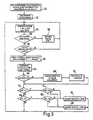
- the stroke magnitude and stroke duration are kinematic parameters, the variability of which is assessed in order to obtain an optimum setting of the swing phase resistance offered by piston and cylinder assembly 18 in each of five different walking speed ranges (represented in Figure 3 by step period ranges T 1 to T 5 ). Different numbers of walking speed ranges may be used.
- and ⁇ T S are determined by comparing the stroke magnitude and stroke duration measurements over a number of consecutive steps, here seven steps, for which T remains within one of the ranges T 1 to T 5 . According to whether these variability values ⁇
- the sequence of operations carried out by the processor circuit 32 begins with selecting either manual programming or automatic programming and selecting either pre-programmed variability values or previously determined variability values ⁇
- the remote control unit referred to in the prior patent application mentioned above is used to send command signals for appropriate valve adjustment and for producing average walking speed values.
- the pre- programmed variability values may be factory set to give a starting point for automatic programming. In some circumstances, if very large variability values are measured, automatic programming may be preceded by manual programming by the prosthetist and reading the previous values of stroke magnitude and stroke duration for each speed range T 1 to T 5 stored in EPROM 38 (program element 50).
- step period, stroke magnitude and stroke duration are measured for each walking step (element 54), and for each walking step the value of the step period T is checked against corresponding limit values of the ranges T 1 to T 5 to determine whether the step being measured is within the same step period range as the previous step (element 56). If it is not, the new step period range is set (element 58) and the program returns to element 54 to measure and store T, ⁇
- step period of the measured step is within the same step period range as the previous step, a counter is incremented (not shown) and the program returns to element 54 to run through the above described sequence again until seven consecutive steps have taken place all within one step period range, as determined by program element 60 in Figure 3.
- step period range is checked and the step magnitude variability and step duration variability are selected and calculated for the respective seven steps (elements 62 and 64 of the program).
- the stroke magnitude variability is compared with the previous value (element 66). If the variability has increased, it is assumed that the last adjustment of valve 18D (Figure 1) in the relevant step period range was in the wrong direction, and the register setting the direction of valve adjustment is updated to reverse the adjustment direction (element 68) and the previous stroke magnitude variability value is overwritten with the new stroke magnitude variability value (element 70).
- the measured stroke magnitude variability value is compared with a first variability threshold A i (element 72) and if that threshold is exceeded, another comparison is carried out in step 74 to determine whether the variability value exceeds a higher second variability threshold, in this case double the previous threshold, i.e. 2A i (element 74).
- the outcome of program elements 72 and 74 is that if the stroke magnitude variability is below the first threshold A i, no valve adjustment occurs. If it is between the first and second thresholds A i and 2A i, the valve is adjusted by half a step of the stepper motor 20 (see Figure 1) in the direction set in the valve adjustment direction register (program element 76).
- the valve is adjusted by one stepper motor step (element 78) in the indicated direction. If the stroke magnitude variability is within the lower of the two stroke magnitude variability thresholds, as determined by program element 72, the variability of the stroke duration is assessed as a secondary variability measure. Thus, in program element 80, the stroke duration variability ⁇ T S is compared against a stroke duration variability threshold B i and, if necessary, against a second stroke duration variability threshold 2B i (in program element 82). Again, depending on the results of these comparisons, the valve 18D is adjusted by half a step or one step in the register- indicated direction, or no adjustment occurs.
- the above-described program elements 54 to 82 form one iteration in an iterative procedure for optimally adjusting valve 18D so as to bring at least the stroke magnitude variability within the lower of its respective threshold (A i ). Accordingly, the next time seven steps are completed within the same step period range, the next iteration occurs, and so on until an optimum valve adjustment is obtained. The same process is carried out for other step period ranges.
- stroke magnitude variability as the primary variability parameter ensures that reduction of stroke magnitude variability takes precedence over reduction of stroke duration variability.
- stroke duration may be adopted as the primary variability measure, the stroke magnitude variability then becoming the secondary variability measure.
- the above-described program operations can be activated by operating a switch or on detection of a special sequence of movements of the prosthesis, or it may be performed continuously during normal use of the prosthesis.
- the effect of the operation is that adjustment of the control device may be carried out automatically without intervention from a prosthetist. After an initial geometric alignment of the limb and, generally, an approximate adjustment of the control device, the fine adjustment of the control device is a self-teaching automatic procedure.
Landscapes
- Health & Medical Sciences (AREA)
- Cardiology (AREA)
- Oral & Maxillofacial Surgery (AREA)
- Transplantation (AREA)
- Engineering & Computer Science (AREA)
- Biomedical Technology (AREA)
- Heart & Thoracic Surgery (AREA)
- Vascular Medicine (AREA)
- Life Sciences & Earth Sciences (AREA)
- Animal Behavior & Ethology (AREA)
- General Health & Medical Sciences (AREA)
- Public Health (AREA)
- Veterinary Medicine (AREA)
- Prostheses (AREA)
- Materials For Medical Uses (AREA)
Claims (18)
- Beinprothese für einen Oberschenkelamputierten, die eine auf dynamische Weise einstellbare Kniebewegungssteuerungseinheit (18, 20, 22 24A, 24B) beinhaltet, welche angeordnet ist zum Steuern der Biegung bzw. Beugung und/oder Verlängerung eines Kniegelenks (10) der Prothese, dadurch gekennzeichnet, dass die Steuerungseinheit angeordnet ist zum automatischen Steuern der Beugung und/oder Verlängerung des Gelenks im Bezug zu der erfassten Schritt-zu-Schritt-Änderung bzw. Schwankung von zumindest einem kinetischen oder kinematischen Parameter der Fortbewegung, um die Schritt-zu-Schritt-Änderung zu reduzieren.
- Prothese nach Anspruch 1, dadurch gekennzeichnet, dass die erfasste Änderung bzw. Variabilität ein elektrischer Signalwert ist, der repräsentativ ist für den Grad der Änderung eines kinematischen Parameters, gemessen während jedem einer Mehrzahl von durch den Amputierten während der Fortbewegung getätigten Schritt.
- Prothese nach Anspruch 2, dadurch gekennzeichnet, dass der kinematische Parameter der Betrag der Kniegelenkbeugung während jedem Schritt ist, der durch den Amputierten innerhalb eines vorbestimmten Bereichs der Fortbewegung getätigt wird.
- Prothese nach Anspruch 3, dadurch gekennzeichnet, dass der Bereich der Fortbewegung ein Geschwindigkeitsbereich ist.
- Prothese nach Anspruch 3 oder Anspruch 4, dadurch gekennzeichnet, dass die Steuerungseinheit eine veränderbare Dämpfervorrichtung (18) beinhaltet, die mit den oberen und unteren Gliedkomponenten (14, 16) gekoppelt ist, welche sich in Bezug zueinander während der Biegung bzw. Beugung und Verlängerung des Kniegelenks (10) bewegen, ein Messwandler (24) der Dämpfervorrichtung zugeordnet ist zum Erzeugen eines elektrischen Messwandlerausgangssignals, das repräsentativ ist für die relative Position von relativ bewegbaren Teilen des Dämpfers, und einen elektrischer Steuerschaltkreis (22) zur Weiterverarbeitung des Messwandlerausgangssignals, um den Änderungssignalwert zu erzeugen und zum Zuführen eines Einstellsignals zu der Dämpfervorrichtung, um die Dämpfung des Kniegelenks in Bezug zu dem Anderungssignalwert, der zumindest einen eingestellten Grenzwert überschreitet, einzustellen.
- Prothese nach einem der vorangehenden Ansprüche, dadurch gekennzeichnet, dass die Steuerungseinheit angeordnet ist, um einen sich wiederholenden Ablauf von wiederholter Änderungserfassung und Steuereinheitseinstellung durchzuführen, um progressiv die Schwankung bzw. Änderung des Parameters im wesentlichen auf ein Minimum zu reduzieren.
- Beinprothese nach Anspruch 1, dadurch gekennzeichnet, dass die Steuerungseinheit eine Kniebewegungssteuerungsvorrichtung (18, 20) beinhaltet, einen Messwandler (24A, 24B) zum Erzeugen eines Erfassungs- bzw. Abtastsignals bezogen auf einen kinematischen Parameter der Fortbewegung, und einen elektronischen Steuerungsschaltkreis (22), der einen mit dem Messwandler gekoppelten Eingang und einen mit der Steuervorrichtung gekoppelten Ausgang besitzt, wobei der Messwandler und der Steuerungsschaltkreis aufgebaut bzw. konfiguriert sind, um die Schritt-zu-Schritt-Schwankung des kinematischen Parameters zu bestimmen und dabei die Ausgangssignale zum Einstellen der Steuervorrichtung zu erzeugen, um die schrittweisen Schwankungen des Parameters zu reduzieren, um auf diese Weise eine optimale Einstellung der Steuerungsvorrichtung zu erreichen.
- Prothese nach Anspruch 7, dadurch gekennzeichnet, dass der Messwandler (24A, 24B) und der Steuerungsschaltkreis (22) aufgebaut sind, um die Schwankung des Parameters über einen bestimmten Bereich der Fortbewegung zu bestimmen und die Ausgangssignale werden erzeugt, um die Steuerungsvorrichtung (18, 20) zu veranlassen, auf eine optimale Einstellung eingestellt zu sein, bei welcher die Schwankung des Parameters im wesentlichen minimiert ist, wenn sich die Fortbewegung innerhalb des genannten Bereichs ist.
- Prothese nach Anspruch 8, dadurch gekennzeichnet, dass der Messwandler (24A, 24B) und der Steuerungsschaltkreis (22) aufgebaut sind, um die Schwankung des Parameters über einen bestimmten Bereich der Fortbewegung zu bestimmen und die Ausgangssignale werden erzeugt, um die Steuerungsvorrichtung (18, 20) zu veranlassen, auf eine Mehrzahl von jeweiligen optimalen Einstellungen, eine für jeden Bereich, eingestellt zu sein, wobei jede Einstellung die Schwankung des Parameters innerhalb des jeweiligen Fortbewegungsbereiches im wesentlichen minimiert.
- Prothese nach Anspruch 8 oder Anspruch 9, dadurch gekennzeichnet, dass der oder jeder Bereich der Fortbewegung ein Schrittperiodenbereich oder ein Bereich von Parameterwerten bezogen auf Schrittperiodenwerte ist.
- Prothese nach Anspruch 8 oder Anspruch 9, dadurch gekennzeichnet, dass der oder jeder Bereich der Fortbewegung eine Fortbewegungskategorie ist, wie vorher definiert.
- Prothese nach einem der Ansprüche 7 bis 11, dadurch gekennzeichnet, dass der kinematische Parameter ein Kniebeugewinkel oder ein Parameter ist, der den Kniebeugewinkel repräsentiert.
- Prothese nach einem der Ansprüche 7 bis 12, dadurch gekennzeichnet, dass der kinematische Parameter eine Schrittlänge ist.
- Prothese nach Anspruch 13, dadurch gekennzeichnet, dass die Schrittlänge als zweiter kinematischer Parameter der vorbestimmten Schwankung benutzt wird.
- Prothese nach einem der vorangehenden Ansprüche, dadurch gekennzeichnet, dass die Steuerungseinheit eine Kniebewegungssteuerungsvorrichtung (18, 20) und einen Steuerungsschaltkreis (22), der einen mit der Steuerungsvorrichtung gekoppelten Ausgang besitzt beinhaltet, und dass der Steuerungsschaltkreis konfiguriert ist, um einen Wert eines kinematischen Parameters während jedem einer Mehrzahl von Fortbewegungszyklen zu speichern, um die gespeicherten Werte zu vergleichen, um eine Schwankungsmessung zu ermitteln, um die Schwankungsmessung mit einem Referenzschwankungswert zu vergleichen und einen Steuerungsvorrichtungseinstellungsablauf einzuleiten, wenn die Schwankungsmessung den Referenzwert überschreitet.
- Prothese nach Anspruch 15, dadurch gekennzeichnet, dass der Steuerungsschaltkreis konfiguriert ist, den Bereich der Fortbewegung vor dem Speichern der kinematischen Werte zu bestimmen und die Schwankungsmessung in Bezug zu einer Mehrzahl von Parameterwerten entsprechend einer Mehrzahl von aufeinanderfolgenden Fortbewegungszyklen innerhalb des genannten Bereichs der Fortbewegung zu ermitteln, wobei der Steuerungsvorrichtungseinstellungsablauf während nachfolgenden Fortbewegungszyklen innerhalb des Bereichs der Fortbewegung durchgeführt wird.
- Steuerungssystem für eine Beinprothese, die eine auf dynamische Weise einstellbare Steuerungsvorrichtung (18, 20) besitzt, die mit einem Gelenk (10) der Prothese verbunden ist, wobei das Steuerungssystem gekennzeichnet ist durch einen Eingang für die Verbindung mit einem Messwandler (24A, 24B) auf der Prothese, welcher ein elektrisches Messwandlersignal in Bezug zur Beugung oder Verlängerung eines Gelenks (10) erstellt, einen Ausgang für die Verbindung mit der Steuerungsvorrichtung (18, 20) zur Beeinflussung des Betriebs des Gelenks während der Fortbewegung, und einen Prozessorschaltkreis (32), angeordnet zum Berechnen eines Schwankungswertes aus dem am Eingang empfangenen Messwandlersignal, das indikativ ist für die Schwankung eines kinematischen Wertes der Fortbewegung von Schritt zu Schritt, und auf automatische Weise in Bezug zu dem Schwankungswert eine bestimmte Bedingung oder Bedingungen erfüllt, um ein Ausgangssignal zu erzeugen, das die Steuerungsvorrichtung veranlasst, auf solch eine Weise eingestellt zu werden, dass die Schwankung der Parameter reduziert wird.
- Steuerungssystem nach Anspruch 17, dadurch gekennzeichnet, dass der Prozessorschaltkreis (32) angeordnet ist, um die Einstellung der Steuerungsvorrichtung (18, 20) durch wechselweises Herleiten eines Schwankungswertes und Einstellen der Steuerungsvorrichtung in einer sich wiederholenden Weise zu optimieren.
Applications Claiming Priority (3)
| Application Number | Priority Date | Filing Date | Title |
|---|---|---|---|
| GBGB9804611.3A GB9804611D0 (en) | 1998-03-04 | 1998-03-04 | Lower limb prosthesis and control unit |
| GB9804611 | 1998-03-04 | ||
| PCT/GB1999/000640 WO1999044547A1 (en) | 1998-03-04 | 1999-03-03 | Lower limb prosthesis and control unit |
Publications (2)
| Publication Number | Publication Date |
|---|---|
| EP1059898A1 EP1059898A1 (de) | 2000-12-20 |
| EP1059898B1 true EP1059898B1 (de) | 2004-06-23 |
Family
ID=10827979
Family Applications (1)
| Application Number | Title | Priority Date | Filing Date |
|---|---|---|---|
| EP99937863A Expired - Lifetime EP1059898B1 (de) | 1998-03-04 | 1999-03-03 | Beinprothese und steuerung dafür |
Country Status (7)
| Country | Link |
|---|---|
| US (1) | US6719806B1 (de) |
| EP (1) | EP1059898B1 (de) |
| AT (1) | ATE269683T1 (de) |
| AU (1) | AU3264399A (de) |
| DE (1) | DE69918273T2 (de) |
| GB (2) | GB9804611D0 (de) |
| WO (1) | WO1999044547A1 (de) |
Families Citing this family (53)
| Publication number | Priority date | Publication date | Assignee | Title |
|---|---|---|---|---|
| US6113642A (en) | 1996-06-27 | 2000-09-05 | Mauch, Inc. | Computer controlled hydraulic resistance device for a prosthesis and other apparatus |
| DE19859931A1 (de) * | 1998-12-24 | 2000-07-06 | Biedermann Motech Gmbh | Beinprothese mit einem künstlichen Kniegelenk und Verfahren zur Steuerung einer Beinprothese |
| DE10000781A1 (de) * | 2000-01-11 | 2001-11-29 | Biedermann Motech Gmbh | Vorrichtung und Verfahren zur Fernwartung einer elektronisch ansteuerbaren Prothese |
| AU771817C (en) | 2000-01-20 | 2005-04-14 | Massachusetts Institute Of Technology | Electronically controlled prosthetic knee |
| ATE378027T1 (de) | 2000-03-29 | 2007-11-15 | Massachusetts Inst Technology | Geschwindigkeitsangepasste und patientenangepasste knieprothese |
| US7736394B2 (en) | 2002-08-22 | 2010-06-15 | Victhom Human Bionics Inc. | Actuated prosthesis for amputees |
| JP4808026B2 (ja) * | 2002-08-22 | 2011-11-02 | ヴィクソム ヒューマン バイオニクス インコーポレーテッド | 膝上部肢切断患者用の駆動源付き義足 |
| US7198071B2 (en) * | 2003-05-02 | 2007-04-03 | Össur Engineering, Inc. | Systems and methods of loading fluid in a prosthetic knee |
| US7101487B2 (en) | 2003-05-02 | 2006-09-05 | Ossur Engineering, Inc. | Magnetorheological fluid compositions and prosthetic knees utilizing same |
| US20050107889A1 (en) | 2003-11-18 | 2005-05-19 | Stephane Bedard | Instrumented prosthetic foot |
| US7815689B2 (en) | 2003-11-18 | 2010-10-19 | Victhom Human Bionics Inc. | Instrumented prosthetic foot |
| US7087090B2 (en) | 2003-11-19 | 2006-08-08 | Bloorview Macmillan Centre | Artificial knee joint |
| US7637959B2 (en) | 2004-02-12 | 2009-12-29 | össur hf | Systems and methods for adjusting the angle of a prosthetic ankle based on a measured surface angle |
| EP1718252B1 (de) * | 2004-02-12 | 2018-01-10 | Össur hf | Vorrichtung und verfahren zur bewegungssteuerung eines fusses |
| CA2559890C (en) | 2004-03-10 | 2014-01-07 | Ossur Hf | Control system and method for a prosthetic knee |
| WO2005110293A2 (en) | 2004-05-07 | 2005-11-24 | Ossur Engineering, Inc. | Magnetorheologically actuated prosthetic knee |
| CA2863933C (en) * | 2004-12-22 | 2018-08-07 | Ossur Hf | Systems and methods for processing limb motion |
| CA2595895C (en) | 2005-02-02 | 2016-06-14 | Ossur Hf | Sensing systems and methods for monitoring gait dynamics |
| US8048007B2 (en) | 2005-02-02 | 2011-11-01 | össur hf | Prosthetic and orthotic systems usable for rehabilitation |
| US8801802B2 (en) | 2005-02-16 | 2014-08-12 | össur hf | System and method for data communication with a mechatronic device |
| SE528516C2 (sv) | 2005-04-19 | 2006-12-05 | Lisa Gramnaes | Kombinerat aktivt och passivt benprotessystem samt en metod för att utföra en rörelsecykel med ett sådant system |
| US7507215B2 (en) | 2005-07-08 | 2009-03-24 | Jri Development Group, Llc | Orthotic brace |
| US7655050B2 (en) | 2005-07-29 | 2010-02-02 | Freedom Innovations, Llc | Computer controlled prosthetic knee device |
| US8299634B2 (en) | 2005-08-10 | 2012-10-30 | Bionic Power Inc. | Methods and apparatus for harvesting biomechanical energy |
| US7485152B2 (en) * | 2005-08-26 | 2009-02-03 | The Ohio Willow Wood Company | Prosthetic leg having electronically controlled prosthetic knee with regenerative braking feature |
| US8048172B2 (en) * | 2005-09-01 | 2011-11-01 | össur hf | Actuator assembly for prosthetic or orthotic joint |
| US7531006B2 (en) * | 2005-09-01 | 2009-05-12 | össur hf | Sensing system and method for motion-controlled foot unit |
| EP1942843B1 (de) | 2005-09-01 | 2017-03-01 | Össur hf | Vorrichtung und verfahren zur bestimmung der änderung des terrains |
| EP1998723B1 (de) * | 2006-03-24 | 2014-05-14 | Blatchford Products Limited | Beinprothese und steuereinheit |
| US20100292807A1 (en) | 2007-11-21 | 2010-11-18 | Juan Jose Ochoa Velez | Stabilising Knee Joint for a Lower Limb Prosthesis |
| DE102008008284A1 (de) * | 2008-02-07 | 2009-08-13 | Otto Bock Healthcare Gmbh | Orthopädisches Kniegelenk sowie Verfahren zur Steuerung eines orthopädischen Kniegelenkes |
| CN102036626B (zh) | 2008-03-24 | 2014-07-02 | 奥瑟Hf公司 | 经股的假肢系统和用于操作该系统的方法 |
| DE102008024746A1 (de) | 2008-05-20 | 2009-12-03 | Otto Bock Healthcare Gmbh | Orthopädietechnische Einrichtung |
| US9351855B2 (en) | 2008-06-16 | 2016-05-31 | Ekso Bionics, Inc. | Powered lower extremity orthotic and method of operation |
| EP2331026B1 (de) * | 2008-06-16 | 2018-11-07 | The Regents of The University of California | Halbbetätigte transfemorale knieprothese |
| US8126736B2 (en) | 2009-01-23 | 2012-02-28 | Warsaw Orthopedic, Inc. | Methods and systems for diagnosing, treating, or tracking spinal disorders |
| US8685093B2 (en) | 2009-01-23 | 2014-04-01 | Warsaw Orthopedic, Inc. | Methods and systems for diagnosing, treating, or tracking spinal disorders |
| US9017418B2 (en) * | 2009-05-05 | 2015-04-28 | össur hf | Control systems and methods for prosthetic or orthotic devices |
| WO2010148134A1 (en) * | 2009-06-17 | 2010-12-23 | össur hf | Feedback control systems and methods for prosthetic or orthotic devices |
| US8661893B2 (en) * | 2010-06-29 | 2014-03-04 | Orthosensor Inc. | Prosthetic component having a compliant surface |
| US8679186B2 (en) * | 2010-06-29 | 2014-03-25 | Ortho Sensor Inc. | Hermetically sealed prosthetic component and method therefor |
| EP2534450B1 (de) * | 2010-02-12 | 2016-04-27 | Freedom Innovations, LLC | Winkelmessvorrichtung und -verfahren |
| US9060884B2 (en) | 2011-05-03 | 2015-06-23 | Victhom Human Bionics Inc. | Impedance simulating motion controller for orthotic and prosthetic applications |
| US8736087B2 (en) | 2011-09-01 | 2014-05-27 | Bionic Power Inc. | Methods and apparatus for control of biomechanical energy harvesting |
| GB201121437D0 (en) | 2011-12-13 | 2012-01-25 | Blatchford & Sons Ltd | A lower limb prothesis |
| US9017419B1 (en) | 2012-03-09 | 2015-04-28 | össur hf | Linear actuator |
| EP3427702B1 (de) | 2013-02-26 | 2024-12-18 | Össur HF | Fussprothese mit verbesserter stabilität und elastischer energierückspeisung |
| DE102015106384B4 (de) * | 2015-04-24 | 2017-09-07 | Otto Bock Healthcare Products Gmbh | Verfahren zur Steuerung einer Dämpfungsveränderung bei einem künstlichen Gelenk |
| US9949850B2 (en) | 2015-09-18 | 2018-04-24 | Össur Iceland Ehf | Magnetic locking mechanism for prosthetic or orthotic joints |
| US10195099B2 (en) | 2016-01-11 | 2019-02-05 | Bionic Power Inc. | Method and system for intermittently assisting body motion |
| GB2576372B (en) | 2018-08-17 | 2023-02-01 | Blatchford Products Ltd | Lower limb prosthesis |
| CN113116609B (zh) * | 2021-04-19 | 2022-03-25 | 吉林大学 | 一种三功能轴可调的膝关节假肢 |
| CN115701796B (zh) | 2021-07-21 | 2025-09-16 | 香港中文大学 | 一种用于人体下肢外骨骼、假肢、矫形器的智能膝关节 |
Family Cites Families (6)
| Publication number | Priority date | Publication date | Assignee | Title |
|---|---|---|---|---|
| US5133774A (en) * | 1988-03-25 | 1992-07-28 | Kabushiki Kaisha Kobe Seiko Sho | Teaching playback swing-phase-controlled above-knee prosthesis |
| US5383939A (en) | 1991-12-05 | 1995-01-24 | James; Kelvin B. | System for controlling artificial knee joint action in an above knee prosthesis |
| GB9312131D0 (en) * | 1993-06-11 | 1993-07-28 | Blatchford & Sons Ltd | Prosthesis control system |
| GB2280609B (en) | 1993-06-11 | 1997-10-08 | Blatchford & Sons Ltd | Prosthesis control system |
| DE19521464C2 (de) | 1995-06-13 | 1999-08-19 | Leuven K U Res & Dev | Verfahren zur Steuerung der Kniebremse eines Prothesen-Kniegelenkes sowie Oberschenkelprothese |
| US6113642A (en) * | 1996-06-27 | 2000-09-05 | Mauch, Inc. | Computer controlled hydraulic resistance device for a prosthesis and other apparatus |
-
1998
- 1998-03-04 GB GBGB9804611.3A patent/GB9804611D0/en not_active Ceased
-
1999
- 1999-03-03 US US09/623,790 patent/US6719806B1/en not_active Expired - Lifetime
- 1999-03-03 DE DE69918273T patent/DE69918273T2/de not_active Expired - Lifetime
- 1999-03-03 WO PCT/GB1999/000640 patent/WO1999044547A1/en not_active Ceased
- 1999-03-03 AU AU32643/99A patent/AU3264399A/en not_active Abandoned
- 1999-03-03 EP EP99937863A patent/EP1059898B1/de not_active Expired - Lifetime
- 1999-03-03 GB GB9904920A patent/GB2334891B/en not_active Expired - Lifetime
- 1999-03-03 AT AT99937863T patent/ATE269683T1/de not_active IP Right Cessation
Also Published As
| Publication number | Publication date |
|---|---|
| AU3264399A (en) | 1999-09-20 |
| DE69918273D1 (de) | 2004-07-29 |
| WO1999044547A1 (en) | 1999-09-10 |
| GB9804611D0 (en) | 1998-04-29 |
| US6719806B1 (en) | 2004-04-13 |
| GB9904920D0 (en) | 1999-04-28 |
| EP1059898A1 (de) | 2000-12-20 |
| GB2334891B (en) | 2002-12-24 |
| ATE269683T1 (de) | 2004-07-15 |
| GB2334891A (en) | 1999-09-08 |
| DE69918273T2 (de) | 2005-07-21 |
Similar Documents
| Publication | Publication Date | Title |
|---|---|---|
| EP1059898B1 (de) | Beinprothese und steuerung dafür | |
| EP1998723B1 (de) | Beinprothese und steuereinheit | |
| EP1003442B1 (de) | Beinprothese | |
| EP1267756B1 (de) | Geschwindigkeitsangepasste und patientenangepasste knieprothese | |
| US5893891A (en) | Prosthesis control system | |
| EP0549855B1 (de) | Einrichtung zum Steuern der Bewegung eines künstlichen Kniegelenks einer Oberschenkelprothese | |
| GB2367753A (en) | A lower limb prosthesis | |
| US6755870B1 (en) | Leg prosthesis with an artificial knee joint and method for controlling a leg prosthesis | |
| JP5560045B2 (ja) | 足首および足の人工装具組立体 | |
| WO2001017466A2 (en) | A lower limb prosthesis | |
| AU2001249759A1 (en) | Speed-adaptive and patient-adaptive prosthetic knee | |
| AU2003236761A1 (en) | Control system and method for controlling an actuated prosthesis | |
| GB2280609A (en) | Adaptive prosthesis control system |
Legal Events
| Date | Code | Title | Description |
|---|---|---|---|
| PUAI | Public reference made under article 153(3) epc to a published international application that has entered the european phase |
Free format text: ORIGINAL CODE: 0009012 |
|
| 17P | Request for examination filed |
Effective date: 20000908 |
|
| AK | Designated contracting states |
Kind code of ref document: A1 Designated state(s): AT DE FR GB SE |
|
| 17Q | First examination report despatched |
Effective date: 20030203 |
|
| GRAP | Despatch of communication of intention to grant a patent |
Free format text: ORIGINAL CODE: EPIDOSNIGR1 |
|
| RBV | Designated contracting states (corrected) |
Designated state(s): AT DE FR SE |
|
| GRAS | Grant fee paid |
Free format text: ORIGINAL CODE: EPIDOSNIGR3 |
|
| RIN1 | Information on inventor provided before grant (corrected) |
Inventor name: SYKES, ANDREW JOHN Inventor name: ZAHEDI, MIR SAEED |
|
| GRAA | (expected) grant |
Free format text: ORIGINAL CODE: 0009210 |
|
| AK | Designated contracting states |
Kind code of ref document: B1 Designated state(s): AT DE FR SE |
|
| PG25 | Lapsed in a contracting state [announced via postgrant information from national office to epo] |
Ref country code: AT Free format text: LAPSE BECAUSE OF FAILURE TO SUBMIT A TRANSLATION OF THE DESCRIPTION OR TO PAY THE FEE WITHIN THE PRESCRIBED TIME-LIMIT Effective date: 20040623 |
|
| REF | Corresponds to: |
Ref document number: 69918273 Country of ref document: DE Date of ref document: 20040729 Kind code of ref document: P |
|
| REG | Reference to a national code |
Ref country code: SE Ref legal event code: TRGR |
|
| PG25 | Lapsed in a contracting state [announced via postgrant information from national office to epo] |
Ref country code: SE Free format text: LAPSE BECAUSE OF NON-PAYMENT OF DUE FEES Effective date: 20050304 |
|
| ET | Fr: translation filed | ||
| PLBE | No opposition filed within time limit |
Free format text: ORIGINAL CODE: 0009261 |
|
| STAA | Information on the status of an ep patent application or granted ep patent |
Free format text: STATUS: NO OPPOSITION FILED WITHIN TIME LIMIT |
|
| 26N | No opposition filed |
Effective date: 20050324 |
|
| EUG | Se: european patent has lapsed | ||
| REG | Reference to a national code |
Ref country code: DE Ref legal event code: R082 Ref document number: 69918273 Country of ref document: DE Representative=s name: ISARPATENT, DE |
|
| REG | Reference to a national code |
Ref country code: DE Ref legal event code: R082 Ref document number: 69918273 Country of ref document: DE Representative=s name: ISARPATENT - PATENTANWAELTE- UND RECHTSANWAELT, DE Effective date: 20120808 Ref country code: DE Ref legal event code: R082 Ref document number: 69918273 Country of ref document: DE Representative=s name: ISARPATENT PATENTANWAELTE BEHNISCH, BARTH, CHA, DE Effective date: 20120808 Ref country code: DE Ref legal event code: R082 Ref document number: 69918273 Country of ref document: DE Representative=s name: ISARPATENT GBR PATENT- UND RECHTSANWAELTE, DE Effective date: 20120808 Ref country code: DE Ref legal event code: R082 Ref document number: 69918273 Country of ref document: DE Representative=s name: ISARPATENT, DE Effective date: 20120808 Ref country code: DE Ref legal event code: R081 Ref document number: 69918273 Country of ref document: DE Owner name: BLATCHFORD PRODUCTS LTD., BASINGSTOKE, GB Free format text: FORMER OWNER: CHAS. A. BLATCHFORD & SONS LTD., BASINGSTOKE, HAMPSHIRE, GB Effective date: 20120808 Ref country code: DE Ref legal event code: R081 Ref document number: 69918273 Country of ref document: DE Owner name: BLATCHFORD PRODUCTS LTD., GB Free format text: FORMER OWNER: CHAS. A. BLATCHFORD & SONS LTD., BASINGSTOKE, GB Effective date: 20120808 |
|
| REG | Reference to a national code |
Ref country code: FR Ref legal event code: TP Owner name: BLATCHFORD PRODUCTS LIMITED, GB Effective date: 20120905 |
|
| REG | Reference to a national code |
Ref country code: FR Ref legal event code: PLFP Year of fee payment: 17 |
|
| REG | Reference to a national code |
Ref country code: FR Ref legal event code: PLFP Year of fee payment: 18 |
|
| REG | Reference to a national code |
Ref country code: FR Ref legal event code: PLFP Year of fee payment: 19 |
|
| PGFP | Annual fee paid to national office [announced via postgrant information from national office to epo] |
Ref country code: DE Payment date: 20170322 Year of fee payment: 19 Ref country code: FR Payment date: 20170322 Year of fee payment: 19 |
|
| REG | Reference to a national code |
Ref country code: DE Ref legal event code: R119 Ref document number: 69918273 Country of ref document: DE |
|
| PG25 | Lapsed in a contracting state [announced via postgrant information from national office to epo] |
Ref country code: DE Free format text: LAPSE BECAUSE OF NON-PAYMENT OF DUE FEES Effective date: 20181002 |
|
| PG25 | Lapsed in a contracting state [announced via postgrant information from national office to epo] |
Ref country code: FR Free format text: LAPSE BECAUSE OF NON-PAYMENT OF DUE FEES Effective date: 20180331 |