EP1059949B1 - Ensemble de canules frangibles et procédés de manipulation - Google Patents
Ensemble de canules frangibles et procédés de manipulation Download PDFInfo
- Publication number
- EP1059949B1 EP1059949B1 EP99904325A EP99904325A EP1059949B1 EP 1059949 B1 EP1059949 B1 EP 1059949B1 EP 99904325 A EP99904325 A EP 99904325A EP 99904325 A EP99904325 A EP 99904325A EP 1059949 B1 EP1059949 B1 EP 1059949B1
- Authority
- EP
- European Patent Office
- Prior art keywords
- tip
- breakable
- bore
- wall
- cannula
- Prior art date
- Legal status (The legal status is an assumption and is not a legal conclusion. Google has not performed a legal analysis and makes no representation as to the accuracy of the status listed.)
- Expired - Lifetime
Links
- 238000000034 method Methods 0.000 title claims description 6
- 230000000712 assembly Effects 0.000 title 1
- 238000000429 assembly Methods 0.000 title 1
- 239000012530 fluid Substances 0.000 claims description 22
- 239000000463 material Substances 0.000 claims description 17
- 239000004417 polycarbonate Substances 0.000 claims description 9
- 229920000515 polycarbonate Polymers 0.000 claims description 9
- 238000005452 bending Methods 0.000 claims description 7
- 229920012485 Plasticized Polyvinyl chloride Polymers 0.000 claims description 4
- 229920000915 polyvinyl chloride Polymers 0.000 claims description 4
- 239000004800 polyvinyl chloride Substances 0.000 claims description 4
- 239000012858 resilient material Substances 0.000 claims description 4
- 210000004369 blood Anatomy 0.000 description 7
- 239000008280 blood Substances 0.000 description 7
- 238000005119 centrifugation Methods 0.000 description 7
- 229920003023 plastic Polymers 0.000 description 4
- 239000004033 plastic Substances 0.000 description 4
- 230000001954 sterilising effect Effects 0.000 description 4
- 238000004659 sterilization and disinfection Methods 0.000 description 4
- 238000004891 communication Methods 0.000 description 3
- 238000006073 displacement reaction Methods 0.000 description 3
- 210000003743 erythrocyte Anatomy 0.000 description 2
- 230000002452 interceptive effect Effects 0.000 description 2
- 210000002381 plasma Anatomy 0.000 description 2
- 230000004044 response Effects 0.000 description 2
- 239000000853 adhesive Substances 0.000 description 1
- 230000001070 adhesive effect Effects 0.000 description 1
- 239000003146 anticoagulant agent Substances 0.000 description 1
- 229940127219 anticoagulant drug Drugs 0.000 description 1
- 210000001754 blood buffy coat Anatomy 0.000 description 1
- 230000000694 effects Effects 0.000 description 1
- 230000012953 feeding on blood of other organism Effects 0.000 description 1
- 229920002457 flexible plastic Polymers 0.000 description 1
- 230000005484 gravity Effects 0.000 description 1
- 210000000265 leukocyte Anatomy 0.000 description 1
- 239000011435 rock Substances 0.000 description 1
- 238000007789 sealing Methods 0.000 description 1
- 239000002904 solvent Substances 0.000 description 1
Images

Classifications
-
- A—HUMAN NECESSITIES
- A61—MEDICAL OR VETERINARY SCIENCE; HYGIENE
- A61M—DEVICES FOR INTRODUCING MEDIA INTO, OR ONTO, THE BODY; DEVICES FOR TRANSDUCING BODY MEDIA OR FOR TAKING MEDIA FROM THE BODY; DEVICES FOR PRODUCING OR ENDING SLEEP OR STUPOR
- A61M39/00—Tubes, tube connectors, tube couplings, valves, access sites or the like, specially adapted for medical use
- A61M39/22—Valves or arrangement of valves
- A61M39/221—Frangible or pierceable closures within tubing
Definitions
- the invention relates to breakable or frangible seals for fluid paths.
- U.S. Patent 5,330,464 discloses a breakable seal located within a fluid path.
- the seal comprises a rigid, break-apart plastic cannula member, which lays within a flexible plastic housing.
- the housing comprises a wall defining a bore including ribbed regions protruding from the wall into the bore.
- the cannula member comprises a base, a tip and a breakable juncfure between the tip and the base.
- the tip comprises projections on both its front and back ends, which engage the wall of the flexible housing to restrain the cannula member, once broken, from moving inside the housing.
- Frangible seals of the type shown in Mathias 464 are widely used in association with multiple blood bag systems. These systems undergo centrifugation during normal use. During centrifugation, the flexible housing, which encloses the cannula member, can bend about the front end of the cannula member. Exposed to centrifugal forces, the projections on the front end of the cannula member can penetrate and even puncture the plastic walls of the housing.
- a breakable cannula assembly for a fluid path comprising a housing comprising a wall defining a bore having an interior diameter and including a ribbed region protruding from the wall into the bore, the ribbed region having a restricted diameter less than the interior diameter of the wall, and a cannula member in the bore comprising a base, tip, a breakable juncture between the tip and base, the tip including a leading portion free of any projection that frictionally engages either the wall or the ribbed region, whereby neither the wall nor the ribbed region constrains movement of the leading portion through the bore when the tip is broken from the base, the tip also including a trailing portion, which carries at least one projection constructed to frictionally engage the ribbed region, whereby the ribbed region constrains movement of the trailing portion through the bore when the tip is broken from the base.
- the breakable cannula member comprises a non-polyvinyl chloride material.
- the non-polyvinyl chloride material comprises polycarbonate.
- the bore has an axis
- the ribbed region includes a number of rings spaced apart along the axis.
- the ribbed region includes a resilient material.
- the resilient material includes plasticized polyvinyl chloride.
- leading portion of the tip terminates with a rounded surface free of projections to frictionally engage the wall or the ribbed region.
- the tip includes a number of radially spaced-apart vanes extending along the tip and together forming the leading portion and the trailing portion.
- the tip includes an axis, and the vanes taper radially from the tip along the axis from a first diameter to a second diameter greater than the first diameter.
- the trailing portion is free of projections making frictional engagement with the wall.
- a fluid handling system comprising, a first container, a second container, and transfer tubing coupled to the first and second containers to convey fluid between the containers, the transfer tubing including a breakable cannula assembly as defined above.
- a method for manipulating a breakable cannula assembly for a fluid path having a resilient housing comprising a wall defining a bore having an axis and an interior diameter and including a ribbed region protruding from the wall into the bore, the ribbed region having a number of rings, spaced apart along the axis, protruding from the wall into the bore, each ring having a restricted diameter less than the interior diameter of the wall, and a cannula member in the bore comprising a base, a tip, a breakable juncture between the tip and base, the tip including a leading portion free of any projections and a trailing portion, which carries at least one projection extending from different sides of the tip and constructed to frictionally engage the rings of the ribbed region, the method comprising the steps of bending the resilient housing in a first direction across the axis to deflect the tip and open the breakable juncture, while also advancing one side of the
- the seal includes a break-apart cannula member.
- the break-apart cannula member is free of any projections on its leading or front portion to frictionally engage the wall of the surrounding flexible housing.
- the housing includes a ribbed region of multiple rings placed inside the housing. The ribbed region frictionally engages a projection on the trailing portion of the cannula member. This singular engagement at the trailing portion of the cannula member constrains movement of the cannula member in the bore, when broken to establish fluid communication.
- the lack of projections on the leading portion of the cannula member protects the housing wall against unintended point contact with the leading portion of the tip.
- the singular restraint which is formed by the frictional contact between the ribbed region and the projection on the trailing portion of the cannula member, is effective to stabilize the position of the cannula member in the housing, when broken to establish fluid communication.
- the breakable cannula assembly further includes a resilient housing, which comprises a wall defining a bore having an axis and an interior diameter.
- the housing also includes a number of rings, spaced apart along the axis, which protrude from the wall into the bore. Each ring has a restricted diameter less than the interior diameter of the wall.
- a cannula member is provided in the bore.
- the cannula member comprises a base, a tip, and a breakable juncture between the tip and base.
- the tip includes a trailing portion, which carries at least one projection extending from different sides of the tip and constructed to frictionally engage the rings.
- the resilient housing can be bent in a first direction across the axis to deflect the tip and open the breakable juncture, while also advancing one side of the projection past a first one of the rings.
- the resilient housing can then be bent in a different, second direction across the axis to pivot the one side of the projection against the first ring, while an other side of the projection advances past the first ring.
- all sides of the projection are located past the first ring, which resists movement of the cannula tip in its direction along the axis of the housing.
- the resilient housing can be bent in a first direction across the axis to deflect the tip and open the breakable juncture, while also advancing one side of the projection past a first one of the rings.
- the resilient housing can then be bent in a different, second direction across the axis to pivot the one side of the projection against the first ring, while an other side of the projection advances past the first ring and also past a second one of the rings.
- the resilient housing can then be returned to alignment with the axis, to pivot the other side of the projection against the second ring while the one side of the projection advances past the second ring.
- all sides of the projection are past the second ring, which resists further movement of the cannula tip in its direction along the axis of the housing.
- a third ring is spaced from the second ring at a position along the axis opposite to the first ring. As a result of the rocking action, all sides of the projection are between the second and third rings. The second ring resists movement of the cannula tip in one direction along the axis of the housing, while the third ring resists movement of the cannula housing in the opposite direction.
- straightforward rocking action both opens the breakable juncture and advances the cannula tip to secure position in the housing.
- Fig. 1 shows a multiple bag system 10, which includes a breakable cannula assembly 12 that embodies the features of the invention.
- the bag system 10 comprises first and second bags 14 and 16 interconnected by a transfer tube 18.
- the cannula assembly 12 normally blocks fluid flow through the transfer tube 18.
- the cannula assembly 12 can be broken open by manual manipulation of the user, to open the transfer tube 18 to fluid flow.
- the bag system 10 is intended to be used to collect and process blood. Still, it should be appreciated that the cannula assembly 12 is well suited for use with other types of containers or other systems that receive, store, or deliver fluids in the medical field.
- the first bag 14 is intended to receive whole blood from a donor.
- the first bag 14 includes another integrally attached tube 20, which carries a phlebotomy needle 22.
- the first bag 14 also contains an anticoagulant solution 24, which mixes with the whole blood conveyed by the tube 20 into the bag 14.
- the tube 20 After collecting a desired unit of whole blood, the tube 20 is sealed and parted.
- the bag system 10 is centrifuged to separate the whole blood in the first bag 14 into components, e.g., red blood cells, plasma, and an intermediate interface containing leukocytes (also called the buffy coat).
- the cannula assembly 12 After centrifugation, the cannula assembly 12 is broken open. Plasma is expressed from the first bag 14 into the second bag 16 through the transfer tube 18, leaving the red blood cells and buffy coat in the first bag 14. The transfer tube 18 is sealed and parted to allow the contents of the first and second bags 14 and 16 to be further processed or stored separately.
- first and second bags 14 and 16 and associated tubes 18 and 20 are made, e.g., from medical grade plasticized polyvinyl chloride material.
- the cannula assembly 12 includes a tubular cannula housing 26, which encloses an interior bore 28.
- the housing 26 is preferably made from a resilient, flexible material, such as plasticized polyvinyl chloride.
- One end of the cannula housing 26 is sealed within a port 30 serving the first bag 14, e.g., by radio frequency heat sealing.
- the free end of the housing 26 is secured to the transfer tube 18, e.g., by solvent or adhesive.
- the free end of the housing 26 has a reduced diameter to receive the transfer tube 18 in a tight slip fit.
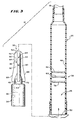
- the cannula assembly 12 also includes a breakable cannula member 32, which Fig. 2 also shows.
- the cannula member 32 is fixed in position within the cannula housing 26 between the port 30 and the transfer tube 18 (see Fig. 4).
- the cannula member 32 is preferably made of a rigid plastic material, such as polycarbonate.
- the cannula member 32 includes a base 34.
- the cannula base 34 has an interior lumen 36.
- the lumen 36 communicates with the port 30.
- the cannula member 32 also includes a tip 38.
- the cannula tip 38 has a back end 40 joined to the base 34.
- the juncture 44 of the back tip end 40 and the base 34 closes the lumen 36, to normally block passage of fluid between the port 30 and the transfer tube 18.
- the cannula tip 38 also includes blunt front end 42, which projects from the base 34 toward the transfer tube 18. As Fig. 4 shows, no part of the blunt front end 42 projects radially outward enough to contact or interfere with the interior wall 46 of the housing bore 28.
- a relatively thin region of material e.g., 0.20 mm in wall thickness
- the base 34 is contoured near the juncture 44 (see Figs. 2 and 3), so that the wall thickness of material diminishes gradually in the direction of the juncture 44. This forms a localized region of weakness at the juncture 44, about which the back tip end 40 can be broken free from the base 34.
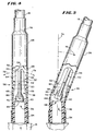
- the user can deflect the tip 38 relative to the base 34 inside the resilient, flexible housing 26 (as shown in Figs. 5 and 6 and by arrows 74 and 78 in Fig. 4).
- This manual manipulation breaks the back tip end 40 from base 34 about the juncture 44.
- the periphery of the juncture 44 defines an open passage 48.
- the passage 48 opens communication between the port 30 and the transfer tube 18 through the base lumen 36 and housing bore 28.
- the parting of the back tip end 40 from the base 34 is made easier and more reliable by forming the cannula member from a rigid plastic material, such as polycarbonate.
- a rigid plastic material such as polycarbonate.
- Polycarbonate is a preferred material because its hardness and dimensions remain unchanged during heat sterilization.
- the use of a polycarbonate material also lends strengths to the juncture 44.
- the polycarbonate material provides mechanical strength in the juncture 44 sufficient to resist unintended movement of the cannula tip 38 relative to base 34 during normal handling, including centrifugation. Still, the polycarbonate material in the juncture 44 yields in a consistent fashion in response to a focused bending force.
- the polycarbonate material also breaks cleanly about the juncture 44 to leave a clear, open annular passage 48.
- the cannula tip 38 also includes at least two radially spaced vanes 50, which extend along the axis of the tip 38.
- the illustrated embodiment shows four vanes 50, which are equally radially spaced about the periphery of the tip 38. The spaces between the vanes 50 form channels 52 through which fluid can flow.
- the vanes 50 of the cannula tip 38 are collectively tapered along the axis of the tip 38, to provide different maximum outside diameters.
- the front or leading portion 64 of the vanes 50 is located about the front tip end 42.
- the diameter of the leading portion 64 is less than the reduced interior diameter of the ribbed area 56, thereby being free of interference or frictional engagement with the interior wall 46 of the bore 28. The potential of puncture or damage to the housing wall 46 by the leading portion 64 during handling or centrifugation is thereby minimized.
- vanes 50 are mutually rounded at the terminus of the front tip end 42, to form a smooth, blunt surface 54.
- This smooth, blunt surface 54 will not puncture or otherwise apply concentrated point contact force against the interior wall 46 of the housing 26, should the housing 26 bend into contact with the cannula tip 38 during handling or centrifugation.
- the vanes 50 also include a back or trailing portion 66.
- the vanes 50 collectively flare or taper outward, forming a ramped surface 68 of increasing diameter toward the back tip end 40.
- the surface 68 ramps the trailing portion 66 to a maximum second diameter.
- the maximum second diameter is generally the same as or less than the interior diameter of the bore 28 outside the ribbed area 56. Therefore, the trailing portion 66 is also free of interference or frictional engagement with the interior wall 46 of the bore 28.
- the leading portion 64 the potential of puncture or damage to the housing wall 46 by the trailing portion 66 during handling or centrifugation is thereby minimized.
- the trailing portion 66 terminates short of the back tip end 40 with a step surface 70.
- the plane of the step surface 70 abruptly reduces the maximum second diameter back to the first diameter, or less, for the remainder of the back tip end 40.
- the cannula tip 38 After being broken free of the base 34, the cannula tip 38 should be moved away from the base passage 48, to assure that fluid flow through the passages 48 is not obstructed. It is important to stabilize the freed cannula tip 38 within the housing 26 against unwanted displacement either toward the base passage 48 or toward the transfer tube 18. This displacement can occur, e.g., due to fluid flow about the cannula tip 38, or due to shaking or gravity forces during normal handling. Unintended displacement of the freed cannula tip 38 can result in an obstruction to fluid flow through the housing 26.
- the cannula housing 26 includes a ribbed area 56 between the cannula passage 48 and the transfer tube 18.
- the ribbed area 56 comprises a number of axially spaced, annular rings 58, 60, and 62.
- the rings 58, 60, and 62 project a set distance outward from the wall 46 into the bore 28 of the housing 26.
- the ribbed area 56 constitutes a localized region where the interior diameter of the housing bore 28 is reduced. In particular, the reduced interior diameter of the ribbed area 56 interferes with the maximum second diameter of the trailing portion 66, but it does not interfere with the first diameter of the leading portion 64.
- Fig. 4 shows, when the cannula member 32 is in its normal, unbroken condition, the ribbed region 56 extends generally along the mid-portion of the cannula tip 38, between the front end 42 and back end 40.
- the outside diameter of the cannula tip 38 is less than the reduced interior diameter of the ribbed region 56. Accordingly, there is no interference between the ribbed region 56 and the cannula tip 38.
- bending the housing 26 in a selected first direction across its axis 76(arrow 74 in Fig. 5) deflects the cannula tip 38 relative to the cannula base 34.
- the deflection breaks the juncture 44 to form the passage 48.
- the deflection also advances the ramp surfaces 68 of the vanes 50 opposite to the direction of the deflection (i.e., on the left side of the tip 38 in Fig. 5) into interference with the first ring 58.
- the left side ramp surfaces 68 will apply radial pressure against the ring 58.
- the first-encountered ring 58 will radially expand or yield, to accommodate passage of the left side ramp surfaces 68 past it. Eventually, the ring 58 encounters the left side step surfaces 70. The resilient, flexible nature of the housing material will return the ring 58 back to its normal restricted dimension. The first-encountered ring 58 will then project into the housing bore 28 behind the left side step surfaces 70.
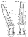
- bending the housing 26 in a second direction across its axis 76 (arrow 78 in Fig. 6) (e.g., to the left in Fig. 6) rocks or deflects the cannula tip 38 in a different path relative to the cannula base 34.
- the left side step surfaces 70 pivot against the first ring 58, as the ramp surfaces 68 opposite to the direction of the deflection (i.e., on the right side of the tip 38 in Fig. 6) advance first into interference with the first ring 58, which resiliently yields to allow passage of the right side step surfaces 70, and next into interference with the second ring 60, which also resiliently yields to allow passage of the right side step surfaces 70 past it.
- the left side step surfaces 70 pivot against the first ring 58, as the opposite right side ramp surfaces 68 advance past the first and second rings 58 and 60.
- Fig. 7 shows, as the housing 26 is returned toward normal alignment with its axis 76 (i.e., moving back to the right from Fig. 6 to Fig. 7), the right side step surfaces 70 pivot against the second ring 60, as the opposite left side ramp surfaces 68 advance past the second ring 60. As Fig. 7 shows, when the housing 26 returns to normal alignment with the axis 76, all step surfaces 70 rest between the ring 60 and the ring 62.
- the ring 60 resists back travel of the cannula tip 38 toward the base passage 48.
- the next adjacent ring 62 also resists forward travel of the cannula tip 38 toward the transfer tube 18.
- the ribbed area 56 stabilizes the position of the cannula tip 26 a suitable distance away from both the base passage 48 and the transfer tube 18, thereby keeping fluid flow through the housing 26 free and not obstructed.
- the presence of the third ring 62 provides security, in case the rocking action applied to gain passage of the cannula tip 38 past the first-encountered ring 58 causes the trailing portion 66 to overshoot the next adjacent ring 60.
- the presence of the third ring 64 checks the overshot, and thereby prevents the cannula tip 38 from moving too far into the housing 26 toward the transfer tube 18.
- the relative spacing between the rings along the housing axis 76 determines the number of rings that the step surfaces 70 will advance past in response to the rocking action. For example, by spacing the two rings 58 and 60 farther apart than is shown in Figs. 4 to 7, the cannula tip 38 can be advanced by rocking action into a secure position between them. In this arrangement, rocking the cannula tip 38 in a first direction away from the housing axis 76 (as Fig. 5 shows) will serve to advance one side of the step surfaces 70 past the first ring 60. Rocking the cannula tip 38 in another direction (as Fig.
- the system 10 includes directions 80 for manipulating the cannula assembly 12 to break the juncture 44 and to secure the position of the cannula tip 38 in the manners just described.
- the housing 26 measures (after steam sterilization) about 55.1 mm in overall length, of which the end surrounding the cannula member 32 constitutes about 41.7 mm in length.
- the housing bore 28 surrounding the cannula member 32 has an interior diameter (after steam sterilization) of about 6.4 mm outside of the ribbed area 56 and an interior diameter of about 6.1 mm about each ring 58, 60, and 62.
- the cannula member 32 measures about 25.6 mm in overall length, of which the base 28 constitutes about 10.5 mm, and the tip 38 constitutes about 15.1 mm.
- the base 28 has an outside diameter of about 6.55 mm, with an inside diameter for the lumen 36 of about 4.86 mm.
- the juncture 44 of the back tip end 40 and the base 34 measures about 4 mm in diameter.
- the leading portion 54 of the vanes 50 has a maximum diameter of about 4 mm
- the trailing portion 66 of the vanes 50 has a maximum diameter of about 6.4 mm (i.e., interfering with the 6.1 mm diameter of the rings 58, 60, and 62, but not interfering with the same 6.4 mm diameter of the bore 28 outside the ribbed area 56).
- the first ring 58 is spaced about 20.5 mm from the closest end of the housing 26 (i.e., the end that is secured in the port 30), the second ring 60 is spaced about 22.9 mm from this end, and the third ring 62 is spaced about 25.3 mm from this end.
- the spacing between adjacent rings is about 2.4 mm. The spacing can, of course, vary somewhat due to the effects of steam sterilization.
Landscapes
- Health & Medical Sciences (AREA)
- Heart & Thoracic Surgery (AREA)
- Pulmonology (AREA)
- Engineering & Computer Science (AREA)
- Anesthesiology (AREA)
- Biomedical Technology (AREA)
- Hematology (AREA)
- Life Sciences & Earth Sciences (AREA)
- Animal Behavior & Ethology (AREA)
- General Health & Medical Sciences (AREA)
- Public Health (AREA)
- Veterinary Medicine (AREA)
- Infusion, Injection, And Reservoir Apparatuses (AREA)
- Surgical Instruments (AREA)
- Physical Or Chemical Processes And Apparatus (AREA)
Claims (12)
- Ensemble de canules cassables (12) pour un circuit de fluide comprenant :un logement (26) comprenant une paroi (46) définissant un alésage (28) présentant un diamètre intérieur et comprenant une région cannelée (56) faisant saillie depuis la paroi (46) à l'intérieur de l'alésage, la région cannelée (56) présentant un diamètre limité inférieur au diamètre intérieur de la paroi (46), etun élément de canule (32) dans l'alésage (28) comprenant une base (34), une pointe (38), une jointure cassable (44) entre la pointe (38) et la base (34), la pointe (38) comprenant une partie avant (64) exempte de toute saillie qui met en prise avec frottement soit la paroi (46), soit la région cannelée (56), moyennant quoi ni la paroi (46), ni la région cannelée (56) ne contraint le mouvement de la partie avant (64) à travers l'alésage (28) quand la pointe (38) est cassée depuis la base (34), la pointe (38) comprenant également une partie arrière (66) qui porte au moins une saillie (68) construite pour mettre en prise avec frottement la région cannelée (56), moyennant quoi la région cannelée (56) contraint le mouvement de la partie arrière (66) à travers l'alésage (28) quand la pointe (38) est cassée depuis la base (34).
- Ensemble de canules cassables (12) selon la revendication 1, dans lequel l'élément de canule (32) comprend un matériau en polychlorure sans vinyle.
- Ensemble de canules cassables (12) selon la revendication 1, dans lequel matériau en polychlorure sans vinyle comprend du polycarbonate.
- Ensemble de canules cassables (12) selon la revendication 1,
dans lequel l'alésage (28) présente un axe, et
dans lequel la région cannelée (56) comprend un nombre d'anneaux (58, 60, 62) espacés le long de l'axe. - Ensemble de canules cassables (12) selon la revendication 1, dans lequel la région cannelée (56) comprend un matériau élastique.
- Ensemble de canules cassables (12) selon la revendication 5, dans lequel le matériau élastique comprend du polychlorure de vinyle plastifié.
- Ensemble de canules cassables (12) selon la revendication 1,
dans lequel la partie avant (64) de la pointe (38) se termine avec une surface arrondie (54) exempte de saillie pour mettre en prise avec frottement la paroi (46) de la région cannelée (56). - Ensemble de canules cassables (12) selon la revendication 1,
dans lequel la pointe (38) comprend un nombre d'aubes espacées radialement (50) s'étendant le long de la pointe (38) et formant ensembles la partie avant (64) et la partie arrière (66). - Ensemble de canules cassables (12) selon la revendication 8,
dans lequel la pointe (38) comprend un axe, et
dans lequel les aubes (50) s'effilent radialement depuis la pointe (38) le long de l'axe d'un premier diamètre à un second diamètre supérieur au premier diamètre. - Ensemble de canules cassables (12) selon la revendication 1,
dans lequel la partie arrière (66) est exempte de saillie créant une mise en prise avec frottement avec la paroi (46). - Système de manipulation de fluide (10) comprenant
un premier récipient (14),
un second récipient (16), et
un tuyau de transfert (18) couplé aux premier et second récipients (14, 16) pour acheminer le fluide entre les récipients, le tuyau de transfert (18) comprenant un ensemble de canules cassables (12) tel que défini selon l'une quelconque des revendications 1 à 10. - Procédé de manipulation d'un ensemble de canules cassables (12) pour un circuit de fluide présentant un logement élastique (26) comprenant une paroi (46) définissant un alésage (28) ayant un axe et un diamètre intérieur et comprenant une région cannelée (56) faisant saillie depuis la paroi (46) à l'intérieur de l'alésage (28), la région cannelée (56) ayant un nombre d'anneaux (58, 60, 62) espacés le long de l'axe, faisant saillie depuis la paroi (46) à l'intérieur de l'alésage (28), chaque anneau (58, 60, 62) présentant un diamètre limité inférieur au diamètre intérieur de la paroi (46), et un élément de canule (32) dans l'alésage (28) comprenant une base (34), une pointe (38), une jointure cassable (44) entre la pointe (38) et la base (34), la pointe (38) comprenant une partie avant (64) exempte de toute saillie et une partie arrière (66), qui porte au moins une saillie (68) s'étendant des différents côtés de la pointe (38) et construite pour mettre en prise avec frottement les anneaux (58, 60, 62) de la région cannelée (56), le procédé consistant à :plier le logement élastique (26) dans une première direction à travers l'axe pour défléchir la pointe (38) et ouvrir la jointure cassable (44), tout en avançant également un côté de la saillie (68) en mise en prise avec frottement avec un premier (58) des anneaux ;plier le logement élastique (26) dans une seconde direction à travers l'axe pour pivoter un côté de la saillie (68) contre le premier anneau (58) alors qu'un autre côté de la saillie (68) avance en mise en prise avec frottement avec un deuxième (60) des anneaux, etfaire revenir le logement élastique (26) en alignement avec l'axe pour pivoter l'autre côté de la saillie (68) contre le deuxième anneau (60) alors que le premier côté de la saillie (68) avance en mise en prise avec frottement avec le deuxième anneau (60), moyennant quoi tous les côtés de la saillie (68) sont en mise en prise avec frottement avec le deuxième anneau (60).
Applications Claiming Priority (3)
| Application Number | Priority Date | Filing Date | Title |
|---|---|---|---|
| US36337 | 1998-03-06 | ||
| US09/036,337 US6132413A (en) | 1998-03-06 | 1998-03-06 | Breakable cannula assemblies and methods for manipulating them |
| PCT/US1999/001716 WO1999044652A1 (fr) | 1998-03-06 | 1999-01-27 | Ensemble de canules frangibles et procedes de manipulation |
Publications (3)
| Publication Number | Publication Date |
|---|---|
| EP1059949A1 EP1059949A1 (fr) | 2000-12-20 |
| EP1059949A4 EP1059949A4 (fr) | 2002-11-27 |
| EP1059949B1 true EP1059949B1 (fr) | 2005-11-30 |
Family
ID=21888038
Family Applications (1)
| Application Number | Title | Priority Date | Filing Date |
|---|---|---|---|
| EP99904325A Expired - Lifetime EP1059949B1 (fr) | 1998-03-06 | 1999-01-27 | Ensemble de canules frangibles et procédés de manipulation |
Country Status (6)
| Country | Link |
|---|---|
| US (1) | US6132413A (fr) |
| EP (1) | EP1059949B1 (fr) |
| AT (1) | ATE311214T1 (fr) |
| DE (1) | DE69928648T2 (fr) |
| ES (1) | ES2255242T3 (fr) |
| WO (1) | WO1999044652A1 (fr) |
Families Citing this family (32)
| Publication number | Priority date | Publication date | Assignee | Title |
|---|---|---|---|---|
| AU6498600A (en) | 1999-07-29 | 2001-02-19 | Baxter International Inc. | Sampling tube holder for blood sampling system |
| US20030176813A1 (en) * | 1999-07-29 | 2003-09-18 | Jean-Marie Mathias | Biological fluid sampling apparatus |
| US7479131B2 (en) * | 1999-07-29 | 2009-01-20 | Fenwal, Inc. | Biological fluid sampling apparatus, assembly and method |
| US7824343B2 (en) * | 1999-07-29 | 2010-11-02 | Fenwal, Inc. | Method and apparatus for blood sampling |
| DE19960226C1 (de) * | 1999-12-14 | 2001-05-10 | Fresenius Ag | Sterilitäterhaltendes Konnektionssystem für medizinische Systeme und dessen Verwendung |
| US6869653B2 (en) | 2001-01-08 | 2005-03-22 | Baxter International Inc. | Port tube closure assembly |
| US6652942B2 (en) | 2001-01-08 | 2003-11-25 | Baxter International Inc. | Assembly for a flowable material container |
| FR2819418B1 (fr) * | 2001-01-17 | 2003-03-14 | Technoflex Sa | Set de transfert notamment pour l'administration d'un melange de liquides a des fins medicales |
| FR2836832B1 (fr) * | 2002-03-08 | 2005-02-04 | Optis France Sa | Ensemble de connexion a usage medical pour le transfert de fluides |
| ITMI20020921A1 (it) * | 2002-04-30 | 2003-10-30 | Haemopharm Industry Ag | Dispositivo per la sommistrazione di farmaci |
| ITMI20022380A1 (it) * | 2002-11-08 | 2004-05-09 | Haemopharm Industry Ag | Dispositivo per la somministrazione di miscele nutrizionali per via parenterale. |
| EP1787667A4 (fr) * | 2004-08-04 | 2010-07-07 | Ajinomoto Kk | Aiguille de communication utilisee pour faire communiquer deux recipients ou plus |
| DE102005019855A1 (de) * | 2005-04-28 | 2006-11-09 | Fresenius Hemocare Gmbh | Leitung, insbesondere Leitung eines Blutschlauch- oder Blutbeutelsystems |
| US8443824B2 (en) * | 2007-10-09 | 2013-05-21 | Fenwal, Inc. | Fluid flow controller |
| US7905873B2 (en) * | 2008-07-03 | 2011-03-15 | Baxter International Inc. | Port assembly for use with needleless connector |
| US8172823B2 (en) | 2008-07-03 | 2012-05-08 | Baxter International Inc. | Port assembly for use with needleless connector |
| US8062280B2 (en) | 2008-08-19 | 2011-11-22 | Baxter Healthcare S.A. | Port assembly for use with needleless connector |
| CA130987S (en) * | 2008-12-12 | 2010-01-22 | Nipro Corp | Pourer for medical container |
| US8394080B2 (en) | 2009-05-14 | 2013-03-12 | Baxter International Inc. | Needleless connector with slider |
| EP2347750A1 (fr) * | 2010-01-26 | 2011-07-27 | Fresenius Kabi Deutschland GmbH | Connecteur pour récipient contenant un agent actif médical |
| FR2968568B1 (fr) * | 2010-12-14 | 2013-01-18 | Maco Pharma Sa | Dispositif destine a rompre au moins un element de fermeture dispose a l'interieur d'un tube souple |
| ITMI20122028A1 (it) * | 2012-11-28 | 2014-05-29 | Delcon S R L | Dispositivo per la rottura di cannule di sacche ematiche, o simili, e relativo procedimento |
| USD764053S1 (en) | 2013-03-15 | 2016-08-16 | Fenwal, Inc. | Breaker for frangible component |
| USD812221S1 (en) | 2013-03-15 | 2018-03-06 | Fenwal, Inc. | Breaker for frangible component |
| US9895822B2 (en) | 2013-03-15 | 2018-02-20 | Fenwal, Inc. | Automated frangible cannula breaker |
| US20150238746A1 (en) * | 2014-02-26 | 2015-08-27 | Baxter Healthcare Sa | Frangible connector closure for tubular connector |
| US11566225B2 (en) | 2014-10-03 | 2023-01-31 | Fenwal, Inc. | Automated system for processing a biological fluid |
| CA2995334C (fr) | 2015-09-14 | 2018-09-04 | Thomas Bruckner | Dispositif de coupure pour agir sur un element de fermeture d'une tubulure medicale |
| WO2017045825A1 (fr) | 2015-09-14 | 2017-03-23 | Fresenius Kabi Deutschland Gmbh | Dispositif de coupure pour agir sur un élément de fermeture d'une tubulure médicale |
| US11109890B2 (en) | 2018-01-25 | 2021-09-07 | Kyphon Sarl | Vertebral body access cannula with enhanced bending stiffness |
| CN113164708A (zh) * | 2018-09-26 | 2021-07-23 | 纳科斯达格医药股份有限公司 | 可配置的流体通道密封装置和方法 |
| JPWO2023171636A1 (fr) * | 2022-03-07 | 2023-09-14 |
Family Cites Families (26)
| Publication number | Priority date | Publication date | Assignee | Title |
|---|---|---|---|---|
| GB572176A (en) * | 1943-09-11 | 1945-09-26 | Leonard Charles Casselle | Improvements in and relating to ampoules and like vessels |
| US3217710A (en) * | 1963-03-25 | 1965-11-16 | Abbott Lab | Blood collection and sampling apparatus provided with separable coupling means |
| US3750645A (en) * | 1970-10-20 | 1973-08-07 | Becton Dickinson Co | Method of collecting blood and separating cellular components thereof |
| JPS5240621Y2 (fr) * | 1974-07-31 | 1977-09-13 | ||
| US4294247A (en) * | 1977-07-25 | 1981-10-13 | Baxter Travenol Laboratories, Inc. | Frangible, resealable closure for a flexible tube |
| US4181140A (en) * | 1978-02-10 | 1980-01-01 | Baxter Travenol Laboratories, Inc. | Frangible resealable closure for a flexible tube having hold open means |
| US4195632A (en) * | 1978-05-03 | 1980-04-01 | Cutter Laboratories, Inc. | Fluid flow valve |
| US4270534A (en) * | 1979-08-08 | 1981-06-02 | Baxter Travenol Laboratories, Inc. | Frangible valve assembly for blood bags and the like |
| US4340049A (en) * | 1979-10-18 | 1982-07-20 | Baxter Travenol Laboratories, Inc. | Breakaway valve |
| US4386622A (en) * | 1979-10-18 | 1983-06-07 | Baxter Travenol Laboratories, Inc. | Breakaway valve |
| JPS57177485A (en) * | 1981-04-22 | 1982-11-01 | Sharp Kk | Ripple removing device in liquid feeder |
| JPS58155866A (ja) * | 1982-03-12 | 1983-09-16 | テルモ株式会社 | 医療用器具およびその製造方法 |
| US4479989A (en) * | 1982-12-02 | 1984-10-30 | Cutter Laboratories, Inc. | Flexible container material |
| US4621634A (en) * | 1984-01-27 | 1986-11-11 | Trutek Research, Inc. | Anesthesia tubing connections |
| US4586928A (en) * | 1984-10-09 | 1986-05-06 | Miles Laboratories, Inc. | Pivoting frangible valve for plastic bags |
| DE8802443U1 (de) * | 1988-02-25 | 1988-09-01 | Schiwa GmbH, 4519 Glandorf | Behälter für Infusionslösungen |
| US5304163A (en) * | 1990-01-29 | 1994-04-19 | Baxter International Inc. | Integral reconstitution device |
| JP2838725B2 (ja) * | 1990-05-02 | 1998-12-16 | テルモ株式会社 | 血液採取器具 |
| JPH0628137Y2 (ja) * | 1990-06-21 | 1994-08-03 | 株式会社ニッショー | 可撓性チユーブ内の閉止具 |
| DE4116474C2 (de) * | 1991-05-21 | 1994-10-06 | Spang & Brands Gmbh | Brechkappe zum Verstopfen eines Schlauchs |
| IT228802Y1 (it) * | 1992-02-14 | 1998-05-21 | Diego Giacomelli | Sistema di chiusura per attacco luer lock |
| US5330464A (en) * | 1992-03-11 | 1994-07-19 | Baxter International Inc. | Reliable breakable closure mechanism |
| US5514123A (en) * | 1993-04-01 | 1996-05-07 | Abbott Laboratories | Sterile formed, filled and sealed flexible container |
| IL107088A (en) * | 1993-09-23 | 1997-01-10 | Travenol Lab Israel Ltd | Multi-compartment bag |
| IT232769Y1 (it) * | 1994-02-23 | 2000-01-19 | Erba Carlo Reagenti Srl | Fiala per reagenti chimici |
| DE29607437U1 (de) * | 1996-04-24 | 1997-08-21 | B. Braun Melsungen Ag, 34212 Melsungen | Medizintechnische Anschlußvorrichtung |
-
1998
- 1998-03-06 US US09/036,337 patent/US6132413A/en not_active Expired - Lifetime
-
1999
- 1999-01-27 EP EP99904325A patent/EP1059949B1/fr not_active Expired - Lifetime
- 1999-01-27 DE DE69928648T patent/DE69928648T2/de not_active Expired - Lifetime
- 1999-01-27 ES ES99904325T patent/ES2255242T3/es not_active Expired - Lifetime
- 1999-01-27 AT AT99904325T patent/ATE311214T1/de not_active IP Right Cessation
- 1999-01-27 WO PCT/US1999/001716 patent/WO1999044652A1/fr not_active Ceased
Also Published As
| Publication number | Publication date |
|---|---|
| WO1999044652A1 (fr) | 1999-09-10 |
| EP1059949A1 (fr) | 2000-12-20 |
| ES2255242T3 (es) | 2006-06-16 |
| ATE311214T1 (de) | 2005-12-15 |
| DE69928648T2 (de) | 2006-08-03 |
| EP1059949A4 (fr) | 2002-11-27 |
| US6132413A (en) | 2000-10-17 |
| DE69928648D1 (de) | 2006-01-05 |
Similar Documents
| Publication | Publication Date | Title |
|---|---|---|
| US6132413A (en) | Breakable cannula assemblies and methods for manipulating them | |
| US5330464A (en) | Reliable breakable closure mechanism | |
| JP2825663B2 (ja) | カテーテル逆止め弁組立体 | |
| EP1704355B1 (fr) | Systeme de valve d'orifice d'injection sans aiguille nettoyable a deplacement fluidique neutre | |
| EP1708955B1 (fr) | Ensemble support de transfert de liquides et procede de transfert de liquides | |
| EP1466645B1 (fr) | connecteur médical et cathéter à demeure | |
| EP0495497B1 (fr) | Cathéter intraveineux | |
| EP0540507B1 (fr) | Aiguille émoussée | |
| EP1793736B1 (fr) | Dispositif pour collecter du sang sans aiguille comprenant une vanne a connecteur male | |
| US7637279B2 (en) | Shuttle valve | |
| EP1440703B1 (fr) | Dispositif de branchement d'un fluide pour ensemble de prelevement sanguin | |
| JP4287952B2 (ja) | コネクタ要素 | |
| US8043265B2 (en) | Internal needle | |
| WO1996040359A1 (fr) | Connecteur medical | |
| JP2000033124A (ja) | シ―ル部品を備えたコネクタ要素 | |
| GB2142240A (en) | Blood bag apparatus | |
| JP3594604B2 (ja) | 流体ポートの再封止部材 | |
| EP1110574B1 (fr) | Ensemble à aiguille doté d'un dispositif pour émousser la pointe permettant de purger l'air | |
| EP2060291B1 (fr) | Seringue jetable sécurisée | |
| JPH04500473A (ja) | 使用を1回に限定された注射筒 | |
| MXPA00008683A (en) | Breakable cannula assemblies and methods for manipulating them | |
| US20240277970A1 (en) | Safety catheter assembly with passive blood control | |
| EP1106201B1 (fr) | Ensemble à aiguille doté d'un dispositif pour émousser la pointe permettant de purger l'air | |
| WO1998025659A1 (fr) | Seringue a extremite de piston pliable | |
| JPH0394766A (ja) | 注射装置 |
Legal Events
| Date | Code | Title | Description |
|---|---|---|---|
| PUAI | Public reference made under article 153(3) epc to a published international application that has entered the european phase |
Free format text: ORIGINAL CODE: 0009012 |
|
| 17P | Request for examination filed |
Effective date: 20000826 |
|
| AK | Designated contracting states |
Kind code of ref document: A1 Designated state(s): AT BE CH DE DK ES FR GB IE IT LI NL SE |
|
| A4 | Supplementary search report drawn up and despatched |
Effective date: 20021015 |
|
| AK | Designated contracting states |
Kind code of ref document: A4 Designated state(s): AT BE CH DE DK ES FR GB IE IT LI NL SE |
|
| RIC1 | Information provided on ipc code assigned before grant |
Free format text: 7A 61M 5/00 A, 7A 61M 39/22 B, 7A 61M 1/02 B |
|
| 17Q | First examination report despatched |
Effective date: 20040419 |
|
| RTI1 | Title (correction) |
Free format text: BREAKABLE CANNULA ASSEMBLIES AND METHODS FOR MANIPULATING THEM |
|
| GRAP | Despatch of communication of intention to grant a patent |
Free format text: ORIGINAL CODE: EPIDOSNIGR1 |
|
| GRAS | Grant fee paid |
Free format text: ORIGINAL CODE: EPIDOSNIGR3 |
|
| GRAA | (expected) grant |
Free format text: ORIGINAL CODE: 0009210 |
|
| AK | Designated contracting states |
Kind code of ref document: B1 Designated state(s): AT BE CH DE DK ES FR GB IE IT LI NL SE |
|
| PG25 | Lapsed in a contracting state [announced via postgrant information from national office to epo] |
Ref country code: LI Free format text: LAPSE BECAUSE OF FAILURE TO SUBMIT A TRANSLATION OF THE DESCRIPTION OR TO PAY THE FEE WITHIN THE PRESCRIBED TIME-LIMIT Effective date: 20051130 Ref country code: CH Free format text: LAPSE BECAUSE OF FAILURE TO SUBMIT A TRANSLATION OF THE DESCRIPTION OR TO PAY THE FEE WITHIN THE PRESCRIBED TIME-LIMIT Effective date: 20051130 Ref country code: AT Free format text: LAPSE BECAUSE OF FAILURE TO SUBMIT A TRANSLATION OF THE DESCRIPTION OR TO PAY THE FEE WITHIN THE PRESCRIBED TIME-LIMIT Effective date: 20051130 |
|
| REG | Reference to a national code |
Ref country code: GB Ref legal event code: FG4D Ref country code: CH Ref legal event code: EP |
|
| REG | Reference to a national code |
Ref country code: IE Ref legal event code: FG4D |
|
| REF | Corresponds to: |
Ref document number: 69928648 Country of ref document: DE Date of ref document: 20060105 Kind code of ref document: P |
|
| PG25 | Lapsed in a contracting state [announced via postgrant information from national office to epo] |
Ref country code: IE Free format text: LAPSE BECAUSE OF NON-PAYMENT OF DUE FEES Effective date: 20060127 |
|
| PG25 | Lapsed in a contracting state [announced via postgrant information from national office to epo] |
Ref country code: SE Free format text: LAPSE BECAUSE OF FAILURE TO SUBMIT A TRANSLATION OF THE DESCRIPTION OR TO PAY THE FEE WITHIN THE PRESCRIBED TIME-LIMIT Effective date: 20060228 Ref country code: DK Free format text: LAPSE BECAUSE OF FAILURE TO SUBMIT A TRANSLATION OF THE DESCRIPTION OR TO PAY THE FEE WITHIN THE PRESCRIBED TIME-LIMIT Effective date: 20060228 |
|
| REG | Reference to a national code |
Ref country code: CH Ref legal event code: PL |
|
| REG | Reference to a national code |
Ref country code: ES Ref legal event code: FG2A Ref document number: 2255242 Country of ref document: ES Kind code of ref document: T3 |
|
| ET | Fr: translation filed | ||
| PLBE | No opposition filed within time limit |
Free format text: ORIGINAL CODE: 0009261 |
|
| STAA | Information on the status of an ep patent application or granted ep patent |
Free format text: STATUS: NO OPPOSITION FILED WITHIN TIME LIMIT |
|
| REG | Reference to a national code |
Ref country code: IE Ref legal event code: MM4A |
|
| 26N | No opposition filed |
Effective date: 20060831 |
|
| REG | Reference to a national code |
Ref country code: GB Ref legal event code: 732E |
|
| REG | Reference to a national code |
Ref country code: FR Ref legal event code: TP |
|
| NLS | Nl: assignments of ep-patents |
Owner name: FENWAL, INC. Effective date: 20080626 |
|
| REG | Reference to a national code |
Ref country code: FR Ref legal event code: PLFP Year of fee payment: 18 |
|
| REG | Reference to a national code |
Ref country code: FR Ref legal event code: PLFP Year of fee payment: 19 |
|
| REG | Reference to a national code |
Ref country code: FR Ref legal event code: PLFP Year of fee payment: 20 |
|
| PGFP | Annual fee paid to national office [announced via postgrant information from national office to epo] |
Ref country code: NL Payment date: 20180126 Year of fee payment: 20 |
|
| PGFP | Annual fee paid to national office [announced via postgrant information from national office to epo] |
Ref country code: ES Payment date: 20180201 Year of fee payment: 20 Ref country code: DE Payment date: 20180129 Year of fee payment: 20 Ref country code: GB Payment date: 20180129 Year of fee payment: 20 |
|
| PGFP | Annual fee paid to national office [announced via postgrant information from national office to epo] |
Ref country code: FR Payment date: 20180125 Year of fee payment: 20 Ref country code: IT Payment date: 20180122 Year of fee payment: 20 Ref country code: BE Payment date: 20180129 Year of fee payment: 20 |
|
| REG | Reference to a national code |
Ref country code: DE Ref legal event code: R071 Ref document number: 69928648 Country of ref document: DE |
|
| REG | Reference to a national code |
Ref country code: NL Ref legal event code: MK Effective date: 20190126 |
|
| REG | Reference to a national code |
Ref country code: GB Ref legal event code: PE20 Expiry date: 20190126 |
|
| REG | Reference to a national code |
Ref country code: BE Ref legal event code: MK Effective date: 20190127 |
|
| PG25 | Lapsed in a contracting state [announced via postgrant information from national office to epo] |
Ref country code: GB Free format text: LAPSE BECAUSE OF EXPIRATION OF PROTECTION Effective date: 20190126 |
|
| REG | Reference to a national code |
Ref country code: ES Ref legal event code: FD2A Effective date: 20211230 |
|
| PG25 | Lapsed in a contracting state [announced via postgrant information from national office to epo] |
Ref country code: ES Free format text: LAPSE BECAUSE OF EXPIRATION OF PROTECTION Effective date: 20190128 |