EP1060100B1 - Traitement des ebauches dans la fabrication de conditionnements - Google Patents
Traitement des ebauches dans la fabrication de conditionnements Download PDFInfo
- Publication number
- EP1060100B1 EP1060100B1 EP99906342A EP99906342A EP1060100B1 EP 1060100 B1 EP1060100 B1 EP 1060100B1 EP 99906342 A EP99906342 A EP 99906342A EP 99906342 A EP99906342 A EP 99906342A EP 1060100 B1 EP1060100 B1 EP 1060100B1
- Authority
- EP
- European Patent Office
- Prior art keywords
- conveyor
- blanks
- conveyors
- conveyed
- conveying
- Prior art date
- Legal status (The legal status is an assumption and is not a legal conclusion. Google has not performed a legal analysis and makes no representation as to the accuracy of the status listed.)
- Expired - Lifetime
Links
- 238000004806 packaging method and process Methods 0.000 title claims abstract description 6
- 238000004519 manufacturing process Methods 0.000 title abstract description 10
- 239000000853 adhesive Substances 0.000 claims abstract description 31
- 230000001070 adhesive effect Effects 0.000 claims abstract description 31
- 235000019504 cigarettes Nutrition 0.000 abstract description 7
- 230000008901 benefit Effects 0.000 description 4
- 238000011144 upstream manufacturing Methods 0.000 description 4
- 230000000694 effects Effects 0.000 description 3
- 238000010276 construction Methods 0.000 description 2
- 239000000463 material Substances 0.000 description 2
- 239000011435 rock Substances 0.000 description 2
- 238000004026 adhesive bonding Methods 0.000 description 1
- 239000011248 coating agent Substances 0.000 description 1
- 238000000576 coating method Methods 0.000 description 1
- 238000009826 distribution Methods 0.000 description 1
- 238000001125 extrusion Methods 0.000 description 1
- 238000010030 laminating Methods 0.000 description 1
- 238000000034 method Methods 0.000 description 1
- 238000003825 pressing Methods 0.000 description 1
- 239000007921 spray Substances 0.000 description 1
Images
Classifications
-
- B—PERFORMING OPERATIONS; TRANSPORTING
- B65—CONVEYING; PACKING; STORING; HANDLING THIN OR FILAMENTARY MATERIAL
- B65H—HANDLING THIN OR FILAMENTARY MATERIAL, e.g. SHEETS, WEBS, CABLES
- B65H37/00—Article or web delivery apparatus incorporating devices for performing specified auxiliary operations
- B65H37/02—Article or web delivery apparatus incorporating devices for performing specified auxiliary operations for applying adhesive
-
- B—PERFORMING OPERATIONS; TRANSPORTING
- B65—CONVEYING; PACKING; STORING; HANDLING THIN OR FILAMENTARY MATERIAL
- B65B—MACHINES, APPARATUS OR DEVICES FOR, OR METHODS OF, PACKAGING ARTICLES OR MATERIALS; UNPACKING
- B65B19/00—Packaging rod-shaped or tubular articles susceptible to damage by abrasion or pressure, e.g. cigarettes, cigars, macaroni, spaghetti, drinking straws or welding electrodes
- B65B19/02—Packaging cigarettes
- B65B19/22—Wrapping the cigarettes; Packaging the cigarettes in containers formed by folding wrapping material around formers
- B65B19/228—Preparing and feeding blanks
-
- B—PERFORMING OPERATIONS; TRANSPORTING
- B65—CONVEYING; PACKING; STORING; HANDLING THIN OR FILAMENTARY MATERIAL
- B65B—MACHINES, APPARATUS OR DEVICES FOR, OR METHODS OF, PACKAGING ARTICLES OR MATERIALS; UNPACKING
- B65B43/00—Forming, feeding, opening or setting-up containers or receptacles in association with packaging
- B65B43/12—Feeding flexible bags or carton blanks in flat or collapsed state; Feeding flat bags connected to form a series or chain
- B65B43/126—Feeding carton blanks in flat or collapsed state
-
- B—PERFORMING OPERATIONS; TRANSPORTING
- B65—CONVEYING; PACKING; STORING; HANDLING THIN OR FILAMENTARY MATERIAL
- B65B—MACHINES, APPARATUS OR DEVICES FOR, OR METHODS OF, PACKAGING ARTICLES OR MATERIALS; UNPACKING
- B65B51/00—Devices for, or methods of, sealing or securing package folds or closures; Devices for gathering or twisting wrappers, or necks of bags
- B65B51/02—Applying adhesives or sealing liquids
- B65B51/026—Applying adhesives or sealing liquids using rotating applicators
-
- B—PERFORMING OPERATIONS; TRANSPORTING
- B31—MAKING ARTICLES OF PAPER, CARDBOARD OR MATERIAL WORKED IN A MANNER ANALOGOUS TO PAPER; WORKING PAPER, CARDBOARD OR MATERIAL WORKED IN A MANNER ANALOGOUS TO PAPER
- B31B—MAKING CONTAINERS OF PAPER, CARDBOARD OR MATERIAL WORKED IN A MANNER ANALOGOUS TO PAPER
- B31B50/00—Making rigid or semi-rigid containers, e.g. boxes or cartons
- B31B50/60—Uniting opposed surfaces or edges; Taping
- B31B50/62—Uniting opposed surfaces or edges; Taping by adhesives
- B31B50/624—Applying glue on blanks
Definitions
- the invention relates to the processing of blanks in the manufacture of packaging and particularly, but not exclusively to apparatus for processing carton blanks in the manufacture of cigarette cartons.
- DE-A-4332186 discloses apparatus for laminating backing sheets of relatively low-grade material with covering sheets of a high-grade material.
- Said low grade sheets are fed from an adhesive applicator machine onto a first conveyor.
- Said high-grade covering sheets are fed from a magazine onto a second conveyor.
- the low-grade sheets are then delivered onto a subsequent third conveyor which may travel at the same speed as the first conveyor or faster or slower than that conveyor.
- the high-grade sheets are fed from the second conveyor on to a fourth conveyor which may travel at the same speed, or faster or slower than the second conveyor.
- Each sheet is then aligned by running-up against a relatively slow moving batten, and then each low-grade sheet is brought into contact with a high-grade covering sheet at a roller.
- GB-A-2282364 discloses apparatus for conveying box blanks from a cutter to a gluer-folder in which the blanks are transported successively on two belts.
- a first belt immediately downstream of the cutter, runs at approximately the same speed as the cutter; and the blanks are held against the first belt by means of a suction device operating at a first reduced pressure.
- a second belt which is positioned immediately downstream of the first belt, runs a little faster than the first and is provided with an associated suction device for pressing the blanks against the second belt with a stronger suction than in the first belt. Accordingly, as the blanks contact the second belt downstream of the first belt, they adhere more strongly to the second belt, which is travelling faster, thus breaking the suction to the first belt and increasing the spacing between the blanks.
- the present invention provides an apparatus for use in processing packaging blanks, said apparatus comprising first conveying means for conveying said blanks, applying means for applying an adhesive or at least one adhesive element to each blank conveyed by said first conveying means, and second conveying means arranged to receive said blanks from said first conveying means; characterised in that said first conveying means comprises two conveyors for conveying two respective streams of blanks, said second conveying means comprises a first conveyor for receiving the stream of blanks conveyed by one of said conveyors and a second conveyor for receiving the said stream of blanks conveyed by the other of said two conveyors, and blank transferring means are provided for transferring blanks between the said conveyors of said second conveying means, wherein at least said first conveyor of said second conveying means is arranged to convey the blanks conveyed thereon at a conveying velocity which is greater than the conveying velocity of the respective one conveyor of said first conveying means such that the stream of blanks conveyed by at least said first conveyor of said second conveying means has a pitch greater than the respective stream of
- multiple streams of blanks which may be moving at a first velocity selected to suit a processing device such as an adhesives applying means can be combined into a single stream of blanks moving at a second velocity which is greater than said first velocity in order to obtain the advantage of the higher processing speed capability of devices such as folding machines which are disposed downstream of the blank transferring means.
- the conveyors of said second conveying means are arranged such that the respective streams of blanks conveyed thereon have a predetermined out of phase relationship such that the respective streams of blanks are staggered with respect to one another.
- said first conveyor and said second conveyor are each arranged to accelerate the streams of blanks conveyed thereon to a conveying velocity greater than the conveying velocity of the respective conveyors of said first conveying means.
- said blank transferring means is arranged to insert the blanks conveyed by said one conveyor of the second conveying means into said spaces between the stream of blanks conveyed by said other conveyor of said second conveying means so as to provide a stream of blanks comprised alternately of blanks from said one conveyor and said other conveyor.
- the pitch of a stream of blanks along a conveying path is altered by having adjacent conveyors operating with different conveying velocities.
- the pitch and speed at which the blanks are conveyed past various processing devices can be readily modified to suit the operating characteristics of those devices and/or two streams of blanks may be combined.
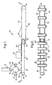
- an apparatus 10 for processing blanks in the manufacture of cartons for cigarettes comprises a carton blank magazine 12 and a blank feeding device 14 for removing blanks from the magazine and feeding them one-by-one onto a conveyor system which is described in detail hereinbelow.
- the device 14 comprises a plurality of arms 16 which are carried on a drum 17.
- the drum is rotatable about a fixed axis as indicated by the arrows 18 in Figure 1.
- the arms 16 are pivotally mounted to the drum 17 so as to be capable of moving back-and-forth in the circumferential direction of the drum and each carries a suction head 20 at its radially outermost end.
- the heads 20 are provided with suction pads (not shown).
- the motion of the arms 16 relative to the drum is controlled by a cam system.
- the effect of the cam system is that as the suction pads of a head 20 engage and grip the lowermost blank held in the magazine, the head rocks back in the direction opposite to the direction of rotation of the drum 17 to facilitate removal of the blank from the magazine. Subsequently, as the arm is carried past the magazine, the head rocks forward (i.e, in the direction of rotation of the drum) under control of the cam system so as to resume a position in which its axis extends radially with respect to the drum.
- the device 14 is described in detail in WO 98/42604 A1.
- the conveyor system comprises a first conveyor 26 which is arranged to receive blanks from the device 14.
- the suction pads of the suction heads 20 are deactivated as the heads approach the conveyor 26 so that the blanks are deposited on the conveyor; blanks deposited on the conveyor are indicated by reference numeral 28 in the figures.
- the conveyor 26 comprises two endless belts 30 which are carried on pulleys 32 disposed at each end of the conveyor. In the usual way, one of the pulleys 32 is driven to cause movement of the belts 30.
- the belts 30 carry battens, or bars, 34 which are known as pushers and extend in a direction transverse to the direction of travel of the belts.
- the pushers 34 are evenly distributed along the length of the belts and serve to engage the trailing edge of the blanks 28 to ensure that the blanks are carried along the length of the conveyor (to the right in Figure 1).
- An adhesives applicator 40 is positioned adjacent the conveyor 26 to apply an adhesive, for example PVA, to a predetermined portion, or portions, of each blank.
- the adhesives applicator 40 is of the wheel-type which is a device well known to those skilled in the art and accordingly will not be described in more detail herein. Suitable wheel-type applicators are described in US2615422, US3162546 and GB2093739.
- a folding machine 44 is disposed downstream of the adhesives applicator 40 and is arranged to fold an upper flap portion 46 of each blank 28 to a position (see the blank 28' in Figure 2) in which it is held by means of the adhesive applied by the applicator.
- the apparatus 10 further comprises a second conveyor 50 which is positioned at the downstream end of the first conveyor 26.
- the construction of the second conveyor 50 corresponds to that of the first conveyor in that it comprises two endless belts 52, two pulleys 54 and transverse battens 56.
- the conveyors 26, 50 are arranged in end-to-end and overlapping relationship so that the blanks 28' are transferred directly from the downstream end of the conveyor 26 to the upstream end of the conveyor 50 thereby maintaining a continuous flow of blanks 28 away from the folding machine 44.
- the conveyors 26, 50 are driven at different speeds. This can be done either by providing individual drive systems which are arranged to provide different operating speeds for the conveyors, or where a common drive unit is utilised, by means of a suitable gearing arrangement.
- the first conveyor 26 is driven at a slower speed than the second conveyor 50; for example, the first conveyor may be driven so as to convey blanks at approximately one half the velocity at which they are conveyed on the second conveyor.
- the spacing between the blanks (i.e, the pitch) on the two conveyors is different.
- the pitch for the blanks on the first conveyor is one half the pitch for the second conveyor.
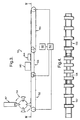
- FIGS 3 and 4 show another apparatus 110 for use in the manufacture of cigarette cartons. Parts of the apparatus which correspond to parts shown in Figures 1 and 2 have been given a similar reference numeral to which 100 has been added.
- the apparatus 110 comprises a carton magazine 112, a blank feeding device 114, a first conveyor 126, an adhesives applicator 140, a folding machine 144 and a second conveyor 150.
- the apparatus 110 comprises a third conveyor 152 which is disposed upstream of the conveyor 126.
- the construction of the third conveyor corresponds to that of the first conveyor 126 and will not therefore be described in detail.
- a motor drive 160 is provided for driving the conveyors 126, 150, 152.
- the motor drive 160 is connected to the conveyors by way of a gearing system 162 which is arranged such that the individual conveyors do not operate at the same speed as described in more detail below.
- the blank feeding device 114 is arranged to feed carton blanks onto the third conveyor 152.
- the blanks on the conveyor 152 are conveyed to the conveyor 126.
- the conveyors 152, 126 are arranged in end-to-end and overlapping relationship so that the blanks are transferred directly from the downstream end of the conveyor 152 onto the upstream end of the conveyor 126. Whilst travelling along the conveyor 126 each of the blanks is subject to gluing and folding operations by the adhesives applicator 140 and folding machine 144.
- the first conveyor 126 conveys blanks at a velocity which is approximately one half that at which they are conveyed by the second conveyor 150.
- the third conveyor 152 conveys the blanks at approximately the same velocity as the second conveyor 150.
- the apparatus 110 has the additional advantage, as compared with the apparatus 10, that the blank feeding device is not restricted to an operating speed which is suited to the adhesives applicator. It will be appreciated that it is not essential for the operating speeds of the conveyors 150, 152 to be the same. Instead, whilst both operate at a higher speed than the conveyor 126, the conveyor 150 might be operated at a higher speed than the conveyor 152.
- the pitch of the stream of blanks conveyed on the conveyor 150 will be greater than that of the stream conveyed by the conveyor 152 which may be desirable to facilitate processing operations to be performed on the blanks downstream of the folding machine 144 and match the speed of the conveyor 152 to the operating speed of the blank feeding device 144.
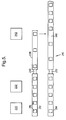
- a third apparatus 210 for use in manufacturing cartons is schematically represented in Figure 5.
- the apparatus 210 comprises two conveyors 212, 214 disposed in a twin track arrangement and each receiving carton blanks 216 from a blank feed device (not shown).
- the conveyors 212, 214 convey the blanks past an adhesives applicator apparatus 220 and a folding apparatus 222.
- the conveyors may be multi-belt conveyors (as shown in Figures 2 and 4) or simply have a single belt and in either case have pushers (not shown) for engaging the trailing edges of the blanks.
- Respective deadplates 230, 232 are provided at the downstream ends of the conveyors 212, 214. Beyond the deadplates are respective conveyors 238, 240. Again these conveyors 238, 240 may have a single-belt or multiple belts as desired and are provided with pushers (not shown) for engaging the trailing edges of the blanks.
- a transfer device 242 is provided adjacent the downstream end of the conveyor 238.
- the transfer device transfers carton blanks from the conveyor 238 to the conveyor 240 and may be a pusher unit which pushes the cartons in a direction transverse to the direction of travel of the conveyors or alternatively some form of pick-and-place device.
- Such apparatus for transferring parts between conveyors will be well known to those skilled in the art and will not therefore be described in detail herein.
- the conveyors 212, 214 convey the blanks 216 at a velocity selected to suit the applicator wheels of the adhesives applicator apparatus 220.
- the blanks are momentarily held on the respective deadplates 230, 232 and then swept onto the respective conveyors 238, 240 as they are engaged by the cross-bars of those conveyors.
- the pushers of the conveyors 238, 240 are arranged to provide a staggered pick up of blanks at the deadplates such that the flow of blanks on those conveyors is out of phase; this phase relationship is shown in Figure 5.
- the conveyors 238, 240 have a conveying velocity which is greater than that of the conveyors 212, 214 which has the result that the pitch of the stream of blanks is increased as the blanks are accelerated at the upstream end of the conveyors 238, 240.
- the transfer device 242 transfers blanks from the downstream end of the conveyor 238 to the conveyor 240, inserting them into the spaces between the blanks on the latter conveyor. As shown, this has the effect of reducing the pitch of the stream of blanks on the conveyor 240 downstream of the transfer device.
- the conveyors 214, 216 may each be conveying 500 blanks per minute whilst downstream of the transfer device 242 the conveyor 240 is conveying 1000 blanks per minute.
- the apparatus 210 allows the combination of two streams of blanks moving at a relatively low speed which is governed by the adhesives applicator and/or the blank feeding devices into one fast moving stream thereby obtaining the benefit of a higher speed capability of apparatus further down the line in the carton making process.
- the apparatus 210 may be simplified by positioning the folding apparatus 222 downstream of the transfer device 242 to operate on the combined flow of blanks conveyed by the conveyor 240. It will also be understood that by suitable selection of the speed of the conveyors 238, 240, the pitch of the combined stream of blanks on the conveyor 240 may be greater than the pitch of the streams of blanks on the conveyors 212, 214.
- the out of phase relationship could be generated by having the conveyors 238, 240 running with different conveying velocities at least one of which is greater than the conveying velocity of the conveyors 214, 216.
- the streams may nonetheless be combined by a suitable arrangement of the transfer device such that the blanks are transferred from the conveyor 238 into the spaces generated by increasing the pitch of the stream of blanks conveyed along the conveying path defined by the conveyors 214, 240.
- the blanks instead of pushing the blanks along path which is substantially normal to the lengthwise direction of the conveyors as shown in Figure 5, the blanks could be pushed at an angle which is inclined to the aforesaid lengthwise direction.
- the apparatus have been described in relation to the application of adhesives to carton blanks by means of wheel-type applicators. Although particularly suited to that purpose, the apparatus is considered equally suitable for use with alternative adhesives application devices such as, for example, spray applicators or extrusion ('slot die') coating devices.
- conveyors are flat-belt conveyors, other conveyors, such as rotary drum conveyors or rotors, would also be suitable.
- the conveyors may utilise a vacuum system to hold the blanks in the required position.
- the apparatus may be used to apply an adhesives carrying element or elements to the blanks.
- an adhesives carrying element or elements For example, as a direct substitute for an adhesive, a double-sided sticky patch could be applied. Alternatively a hologram, coupon or a label carrying an adhesive on its rear face may be applied to the blanks. Alternatively the adhering element may adhere to the blank by virtue of an adhesive, which may be heat or pressure activated, carried by the blank.
- the invention is applicable to processing situations other than the application of an adhesive to a carton blank in which it is desired to alter the pitch of the parts conveyed and/or merge parallel running streams of parts into a single stream.
Landscapes
- Engineering & Computer Science (AREA)
- Mechanical Engineering (AREA)
- Making Paper Articles (AREA)
Abstract
Claims (11)
- Dispositif à utiliser dans le traitement des ébauches de conditionnement, ledit dispositif comprenant des premiers moyens de transport pour transporter lesdites ébauches, des moyens d'application pour appliquer un adhésif ou au moins un élément adhésif sur chaque ébauche transportée par lesdits premiers moyens de transport, des deuxièmes moyens de transport arrangés pour recevoir lesdites ébauches à partir desdits premiers moyens de transport; caractérisé en ce que lesdits premiers moyens de transport comprennent deux convoyeurs (212, 214) pour transporter deux courants respectifs d'ébauches (216), et lesdits deuxièmes moyens de transport comprennent un premier convoyeur (240) pour recevoir le courant d'ébauches transporté par un premier desdits convoyeurs (212, 214), et un deuxième convoyeur (238) pour recevoir ledit courant d'ébauches transporté par l'autre desdits deux convoyeurs (212, 214), et des moyens de transfert d'ébauche (230, 232) sont prévus pour transférer les ébauches entre lesdits convoyeurs desdits deuxièmes moyens de transport, dans lequel au moins ledit premier convoyeur (240) desdits deuxièmes moyens de transport est arrangé pour transporter les ébauches transportées sur celui-ci à une vitesse supérieure à la vitesse de transport du premier convoyeur respectif (212, 214) desdits premiers moyens de transport, de telle sorte que le courant d'ébauches transporté par au moins ledit premier convoyeur (240) desdits deuxièmes moyens de transport ait un pas supérieur au courant respectif d'ébauches transporté par ledit premier convoyeur (212, 214), et lesdits moyens de transfert d'ébauche sont adaptés pour insérer les ébauches transportées par ledit deuxième convoyeur (238) dans des espaces entre les ébauches du courant d'ébauches transporté par ledit premier convoyeur (240).
- Dispositif selon la revendication 1, caractérisé en ce que les convoyeurs (238, 240) desdits deuxièmes moyens de transport sont arrangés de telle sorte que les courants respectifs d'ébauches transportés sur ceux-ci se trouvent dans une relation déphasée, de telle sorte que les courants respectifs d'ébauches soient décalés les uns par rapport aux autres.
- Dispositif selon la revendication 1 ou 2, caractérisé en ce que ledit premier convoyeur (240) et ledit deuxième convoyeur (238) sont chacun arrangés de manière à accélérer les courants d'ébauches transportés sur ceux-ci jusqu'à atteindre une vitesse de transport supérieure à la vitesse de transport des convoyeurs respectifs (214, 212) desdits premiers moyens de transport.
- Dispositif selon l'une quelconque des revendications précédentes, caractérisé en ce que chaque transporteur (238, 240) desdits deuxièmes moyens de transport comprend une pluralité d'éléments sensiblement uniformément espacés (56) arrangés pour engager un bord arrière des ébauches transportées sur ceux-ci.
- Dispositif selon l'une quelconque des revendications précédentes, caractérisé en ce que lesdits moyens de transfert d'ébauche sont arrangés pour insérer les ébauches transportées par ledit deuxième transporteur (238) dans des espaces entre le courant d'ébauches transporté par ledit premier convoyeur (240) de manière à former un courant d'ébauches constitué alternativement d'ébauches provenant dudit premier convoyeur et d'ébauches provenant dudit deuxième convoyeur.
- Dispositif selon l'une quelconque des revendications précédentes, caractérisé en ce que lesdits moyens de transfert d'ébauche sont arrangés de manière à pousser les ébauches dudit deuxième convoyeur (238) sur ledit premier convoyeur (240).
- Dispositif selon l'une quelconque des revendications précédentes, caractérisé en ce que ledit premier convoyeur (240) et ledit deuxième convoyeur (238) sont disposés dans une relation espacée sensiblement parallèle, et lesdits moyens de transfert d'ébauche sont arrangés pour déplacer les ébauches dudit deuxième convoyeur vers ledit premier convoyeur en déplaçant lesdites ébauches dans une direction normale à la direction de déplacement dudit premier convoyeur et dudit deuxième convoyeur.
- Dispositif selon l'une quelconque des revendications précédentes, caractérisé par des plaques mortes respectives (230, 232) disposées entre lesdits convoyeurs desdits premiers moyens de transport et lesdits convoyeurs desdits deuxièmes moyens de transport.
- Dispositif selon l'une quelconque des revendications précédentes, caractérisé en ce que lesdits moyens d'application (220) comprennent une pluralité de roues d'applicateur pour appliquer un adhésif arrangées de telle sorte que chaque convoyeur desdits premiers moyens de transport (212, 214) comprenne au moins une roue d'applicateur qui lui est associée.
- Dispositif selon l'une quelconque des revendications précédentes, caractérisé par des moyens d'alimentation d'ébauche pour amener des ébauches une par une sur chaque convoyeur (212, 214) desdits premiers moyens de transport afin de former lesdits courants respectifs d'ébauches de carton (216).
- Dispositif selon la revendication 10, caractérisé en ce que lesdits moyens d'alimentation et lesdits convoyeurs (212, 214) desdits premiers moyens de transport sont arrangés de telle sorte que lesdits courants respectifs d'ébauches aient sensiblement le même pas et se trouvent dans une relation en phase.
Applications Claiming Priority (3)
| Application Number | Priority Date | Filing Date | Title |
|---|---|---|---|
| GB9803964 | 1998-02-24 | ||
| GBGB9803964.7A GB9803964D0 (en) | 1998-02-24 | 1998-02-24 | Processing blanks in the manufacture of packaging |
| PCT/GB1999/000547 WO1999043552A1 (fr) | 1998-02-24 | 1999-02-23 | Traitement des ebauches dans la fabrication de conditionnements |
Publications (2)
| Publication Number | Publication Date |
|---|---|
| EP1060100A1 EP1060100A1 (fr) | 2000-12-20 |
| EP1060100B1 true EP1060100B1 (fr) | 2006-10-11 |
Family
ID=10827570
Family Applications (1)
| Application Number | Title | Priority Date | Filing Date |
|---|---|---|---|
| EP99906342A Expired - Lifetime EP1060100B1 (fr) | 1998-02-24 | 1999-02-23 | Traitement des ebauches dans la fabrication de conditionnements |
Country Status (6)
| Country | Link |
|---|---|
| US (1) | US6855100B1 (fr) |
| EP (1) | EP1060100B1 (fr) |
| CN (1) | CN1123494C (fr) |
| DE (1) | DE69933546T2 (fr) |
| GB (1) | GB9803964D0 (fr) |
| WO (1) | WO1999043552A1 (fr) |
Families Citing this family (13)
| Publication number | Priority date | Publication date | Assignee | Title |
|---|---|---|---|---|
| ATE494221T1 (de) * | 2006-03-08 | 2011-01-15 | Manroland Ag | Applikationsvorrichtung für elektronische bauteile |
| ITBO20120031A1 (it) * | 2012-01-26 | 2012-04-26 | Gd Spa | Macchina impacchettatrice e metodo di incarto per realizzare una confezione di articoli da fumo con apertura a scorrimento e con coperchio incernierato e scatolato. |
| US20140196403A1 (en) * | 2013-01-11 | 2014-07-17 | Stork Fabricators, Inc. | Automated Systems and Methods for Combining Cards and Products |
| US8812152B1 (en) | 2013-02-22 | 2014-08-19 | TamiCare, Ltd. | Method and apparatus for changing carriage speed on a closed-loop track |
| CN105228934B (zh) * | 2013-03-18 | 2018-04-06 | 鲍勃斯脱梅克斯股份有限公司 | 在输送期间排出平的物件的装置 |
| CN103144798B (zh) * | 2013-03-22 | 2015-01-14 | 龙岩烟草工业有限责任公司 | 一种卷烟条盒包装机的胶缸防松锁紧装置和包装机 |
| CA2823591A1 (fr) * | 2013-08-14 | 2015-02-14 | Beaver Machine Corporation | Systeme et appareil de separation de produits |
| ES2628729T3 (es) * | 2013-10-08 | 2017-08-03 | Bobst Mex Sa | Máquina de fabricación de envases de tipo plegadora-encoladora |
| ITUB20153402A1 (it) * | 2015-09-03 | 2017-03-03 | N&W Global Vending S P A | Erogatore di cialde |
| BR112018004276B1 (pt) | 2015-09-02 | 2022-12-20 | Evoca S.P.A. | Distribuidor de cápsulas e módulo para distribuição de cápsulas |
| CN109532092B (zh) * | 2018-11-12 | 2021-01-26 | 江苏联通纪元印务股份有限公司 | 一体式烟盒成型机构 |
| CN111152988B (zh) * | 2019-12-27 | 2021-07-27 | 安徽虹源医药包装有限公司 | 一种包装盒的自动粘合装置 |
| IT202200004976A1 (it) * | 2022-03-15 | 2023-09-15 | Plusline S R L | Macchina incartonatrice. |
Family Cites Families (19)
| Publication number | Priority date | Publication date | Assignee | Title |
|---|---|---|---|---|
| GB1021603A (fr) | 1900-01-01 | |||
| US2615422A (en) | 1950-08-01 | 1952-10-28 | Hall Printing Co W F | Gluing device |
| GB963360A (en) | 1961-06-01 | 1964-07-08 | Albert George Jeffreys | Apparatus for applying patches of adhesive to blanks in automatic machines |
| CA899615A (en) * | 1970-08-25 | 1972-05-09 | Somerville Industries Limited | Sealing compound applicator |
| US3772971A (en) * | 1971-05-27 | 1973-11-20 | Taylor M L | Batch stacker |
| CH553709A (de) * | 1973-07-09 | 1974-09-13 | Sig Schweiz Industrieges | Foerderanlage mit vorrichtung zum trennen von in gegenseitiger beruehrung auf einem eingangsfoerderer zulaufenden gegenstaenden. |
| US4006831A (en) * | 1974-03-06 | 1977-02-08 | Electra Food Machinery, Inc. | Automatic tortilla counter and stacker |
| DE3108089C2 (de) | 1981-03-04 | 1987-01-15 | Focke & Co, 2810 Verden | Vorrichtung zum Auftragen von Leim auf Lappen von Verpackungen |
| FR2527573A1 (fr) * | 1982-05-27 | 1983-12-02 | Cuir Sa | Procede et dispositif de transfert d'une feuille de materiau d'un ensemble a un autre |
| CH664343A5 (fr) | 1985-11-11 | 1988-02-29 | Bobst Sa | Dispositif pour former des lots separes d'objets plats a partir d'une nappe d'objets en mouvement. |
| GB2195926B (en) | 1986-08-08 | 1991-01-02 | Gd Spa | Device for applying adhesive on to sheets of packing material |
| US5092827A (en) * | 1989-09-28 | 1992-03-03 | International Paper Box Machine Co., Inc. | Apparatus for folding paper boxes |
| US5230686A (en) * | 1992-08-19 | 1993-07-27 | International Paper Box Machine Co., Inc. | Apparatus for folding paper boxes |
| DE4332186C2 (de) * | 1993-09-22 | 1996-09-12 | Condex Maschinenbau Gmbh | Verfahren und Vorrichtung zum Kaschieren von Flachmaterial-Zuschnitten |
| GB2282364A (en) * | 1993-09-29 | 1995-04-05 | Langston Corp | Spacing fed articles, e.g. box blanks |
| DE4439198A1 (de) * | 1994-11-06 | 1996-05-09 | Klett Alfred | Vorrichtung zur Bearbeitung eines entlang eines Förderwegs mit vorgegebener Fördergeschwindigkeit geförderten Zuschnitts |
| US5853360A (en) * | 1995-06-16 | 1998-12-29 | J & L Development, Inc. | Method and apparatus for producing a gusseted container |
| DE19529139A1 (de) | 1995-08-08 | 1997-02-13 | Focke & Co | Vorrichtung zum geordneten Transport von Packungen, insbesondere in Verbindung mit einem Etikettierer |
| IT1285513B1 (it) | 1996-02-02 | 1998-06-08 | Gd Spa | Metodo per l'alimentazione di sbozzati in una macchina impacchettatrice di sigarette |
-
1998
- 1998-02-24 GB GBGB9803964.7A patent/GB9803964D0/en not_active Ceased
-
1999
- 1999-02-23 WO PCT/GB1999/000547 patent/WO1999043552A1/fr not_active Ceased
- 1999-02-23 DE DE69933546T patent/DE69933546T2/de not_active Expired - Fee Related
- 1999-02-23 CN CN99804772A patent/CN1123494C/zh not_active Expired - Fee Related
- 1999-02-23 EP EP99906342A patent/EP1060100B1/fr not_active Expired - Lifetime
-
2000
- 2000-08-22 US US09/642,585 patent/US6855100B1/en not_active Expired - Fee Related
Also Published As
| Publication number | Publication date |
|---|---|
| GB9803964D0 (en) | 1998-04-22 |
| EP1060100A1 (fr) | 2000-12-20 |
| CN1296453A (zh) | 2001-05-23 |
| DE69933546D1 (de) | 2006-11-23 |
| WO1999043552A1 (fr) | 1999-09-02 |
| DE69933546T2 (de) | 2007-01-18 |
| US6855100B1 (en) | 2005-02-15 |
| CN1123494C (zh) | 2003-10-08 |
Similar Documents
| Publication | Publication Date | Title |
|---|---|---|
| EP1060100B1 (fr) | Traitement des ebauches dans la fabrication de conditionnements | |
| NL1006370C2 (nl) | Transportinrichting voor het versnellen van een reeks producten. | |
| US10766644B2 (en) | Apparatus and method for forming a carton | |
| US4714515A (en) | Straight line container labeling apparatus | |
| US5082520A (en) | Automatic high-speed labeling machine employing various linear and rotational speeds of the container | |
| US3955481A (en) | Apparatus for adhering traveling strip material to folded blank boxes | |
| EP2755906B1 (fr) | Système d'acheminement de cartons | |
| GB2225979A (en) | Method and apparatus for securing clasps to envelopes | |
| US5024717A (en) | Labelling apparatus | |
| EP3263470B1 (fr) | Groupe d'étiquetage et procédé pour appliquer une pluralité d'étiquettes sur des articles respectifs | |
| JP3991120B2 (ja) | 扁平な発送物のための搬送システム | |
| EP0711719B1 (fr) | Méthode pour transférer à distances égales des produits et ligne de transport à cet effet | |
| JP4580381B2 (ja) | オンサートを折り畳んでそれを消費者商品に貼り付ける方法及び装置 | |
| US7234696B2 (en) | Method of, and apparatus for, handling blanks, in particular coupons | |
| GB2285964A (en) | Interruption of labelling | |
| CA1222481A (fr) | Etiqueteuses mecaniques | |
| EP0795472A1 (fr) | Procédé pour envelopper des paquets | |
| US5287954A (en) | Device for equally-spaced in-line transportation of randomly arranged incoming products | |
| US3998447A (en) | Method and apparatus for folding flaps of a sanitary pad | |
| US5112430A (en) | Apparatus for applying a sheet to a substrate | |
| US5309697A (en) | Chewing gum packaging machine | |
| US12534259B2 (en) | Method and apparatus for forming groups of absorbent sanitary articles | |
| JP3793232B2 (ja) | 印刷物ストリームの搬送方法及び装置 | |
| GB2263894A (en) | Wrapping labeling device | |
| US3974748A (en) | Apparatus for collating sheet like elements |
Legal Events
| Date | Code | Title | Description |
|---|---|---|---|
| PUAI | Public reference made under article 153(3) epc to a published international application that has entered the european phase |
Free format text: ORIGINAL CODE: 0009012 |
|
| 17P | Request for examination filed |
Effective date: 20000821 |
|
| AK | Designated contracting states |
Kind code of ref document: A1 Designated state(s): DE GB IT |
|
| 17Q | First examination report despatched |
Effective date: 20020531 |
|
| GRAP | Despatch of communication of intention to grant a patent |
Free format text: ORIGINAL CODE: EPIDOSNIGR1 |
|
| GRAS | Grant fee paid |
Free format text: ORIGINAL CODE: EPIDOSNIGR3 |
|
| GRAA | (expected) grant |
Free format text: ORIGINAL CODE: 0009210 |
|
| AK | Designated contracting states |
Kind code of ref document: B1 Designated state(s): DE GB IT |
|
| PG25 | Lapsed in a contracting state [announced via postgrant information from national office to epo] |
Ref country code: IT Free format text: LAPSE BECAUSE OF FAILURE TO SUBMIT A TRANSLATION OF THE DESCRIPTION OR TO PAY THE FEE WITHIN THE PRESCRIBED TIME-LIMIT;WARNING: LAPSES OF ITALIAN PATENTS WITH EFFECTIVE DATE BEFORE 2007 MAY HAVE OCCURRED AT ANY TIME BEFORE 2007. THE CORRECT EFFECTIVE DATE MAY BE DIFFERENT FROM THE ONE RECORDED. Effective date: 20061011 |
|
| REG | Reference to a national code |
Ref country code: GB Ref legal event code: FG4D |
|
| REF | Corresponds to: |
Ref document number: 69933546 Country of ref document: DE Date of ref document: 20061123 Kind code of ref document: P |
|
| PLBE | No opposition filed within time limit |
Free format text: ORIGINAL CODE: 0009261 |
|
| STAA | Information on the status of an ep patent application or granted ep patent |
Free format text: STATUS: NO OPPOSITION FILED WITHIN TIME LIMIT |
|
| 26N | No opposition filed |
Effective date: 20070712 |
|
| PGFP | Annual fee paid to national office [announced via postgrant information from national office to epo] |
Ref country code: DE Payment date: 20090216 Year of fee payment: 11 |
|
| PGFP | Annual fee paid to national office [announced via postgrant information from national office to epo] |
Ref country code: GB Payment date: 20090226 Year of fee payment: 11 |
|
| PGFP | Annual fee paid to national office [announced via postgrant information from national office to epo] |
Ref country code: IT Payment date: 20090122 Year of fee payment: 11 |
|
| GBPC | Gb: european patent ceased through non-payment of renewal fee |
Effective date: 20100223 |
|
| PG25 | Lapsed in a contracting state [announced via postgrant information from national office to epo] |
Ref country code: DE Free format text: LAPSE BECAUSE OF NON-PAYMENT OF DUE FEES Effective date: 20100901 |
|
| PG25 | Lapsed in a contracting state [announced via postgrant information from national office to epo] |
Ref country code: GB Free format text: LAPSE BECAUSE OF NON-PAYMENT OF DUE FEES Effective date: 20100223 Ref country code: IT Free format text: LAPSE BECAUSE OF NON-PAYMENT OF DUE FEES Effective date: 20100223 |