EP1060809A1 - Outil d' élargissement de tubes - Google Patents
Outil d' élargissement de tubes Download PDFInfo
- Publication number
- EP1060809A1 EP1060809A1 EP00111236A EP00111236A EP1060809A1 EP 1060809 A1 EP1060809 A1 EP 1060809A1 EP 00111236 A EP00111236 A EP 00111236A EP 00111236 A EP00111236 A EP 00111236A EP 1060809 A1 EP1060809 A1 EP 1060809A1
- Authority
- EP
- European Patent Office
- Prior art keywords
- expanding tool
- expanding
- web
- tool according
- working diameter
- Prior art date
- Legal status (The legal status is an assumption and is not a legal conclusion. Google has not performed a legal analysis and makes no representation as to the accuracy of the status listed.)
- Granted
Links
- 239000010410 layer Substances 0.000 description 11
- 238000000034 method Methods 0.000 description 8
- 239000012790 adhesive layer Substances 0.000 description 3
- 230000006378 damage Effects 0.000 description 3
- 229920003023 plastic Polymers 0.000 description 3
- 239000004033 plastic Substances 0.000 description 3
- 239000004698 Polyethylene Substances 0.000 description 2
- XAGFODPZIPBFFR-UHFFFAOYSA-N aluminium Chemical compound [Al] XAGFODPZIPBFFR-UHFFFAOYSA-N 0.000 description 2
- 229910052782 aluminium Inorganic materials 0.000 description 2
- 239000002131 composite material Substances 0.000 description 2
- -1 polyethylene Polymers 0.000 description 2
- 229920000573 polyethylene Polymers 0.000 description 2
- 244000089486 Phragmites australis subsp australis Species 0.000 description 1
- 230000004323 axial length Effects 0.000 description 1
- 238000006243 chemical reaction Methods 0.000 description 1
- 238000011109 contamination Methods 0.000 description 1
- 238000006073 displacement reaction Methods 0.000 description 1
- 239000000463 material Substances 0.000 description 1
- 238000005476 soldering Methods 0.000 description 1
- 230000007704 transition Effects 0.000 description 1
Images
Classifications
-
- B—PERFORMING OPERATIONS; TRANSPORTING
- B21—MECHANICAL METAL-WORKING WITHOUT ESSENTIALLY REMOVING MATERIAL; PUNCHING METAL
- B21D—WORKING OR PROCESSING OF SHEET METAL OR METAL TUBES, RODS OR PROFILES WITHOUT ESSENTIALLY REMOVING MATERIAL; PUNCHING METAL
- B21D41/00—Application of procedures in order to alter the diameter of tube ends
- B21D41/02—Enlarging
Definitions
- the invention relates to an expanding tool for pipes according to the preamble of claim 1.
- Such expanding tools are mainly used in the sanitary area, to widen the ends of pipes cylindrically.
- a second tube is inserted at the end of the tube and with it connected by soldering.
- These expanding tools have several Expanding sections that are axially displaceable in the expanding tool Thorn can be moved radially outwards.
- the expansion sections are sector-shaped and lie in the Starting position to each other. As they expand, they will displaced radially outward by the mandrel, being apart from each other be removed. As a result, the outer circumference gaps between the individual sector-shaped expansion sections consist. They cause the widened pipe end in this Areas is not around. The pipe end thus widened therefore points a polygonal interior outline.
- the invention is based, the generic expanding tool to be designed so that the pipe ends are perfectly cylindrical can be expanded with little stress on the pipe can.
- the tool according to the invention results from the thread-like shape extending web, in the feed direction of the expanding tool seen one to expand over the inner circumference of the Rohres linear contact between the web and the inner wall of the pipe. Because this line contact is helical takes place, the pipe to be expanded is only slightly stressed, so that there is no risk that it will be damaged during the expansion process or even destroyed. Due to the helical shape of the Web also results in a perfect cylindricity of the expanded Pipe end.
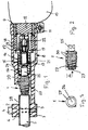
- the expanding device has two clamping jaws 2 as a holding device and 3, which are connected by clamping screws 4 can. Between the two jaws 2 and 3, the are to be expanded Pipes 5 clamped. In the jaws 2, 3 are in Cross-section each provided approximately semicircular depressions 6, 7, in which the pipe 5 to be expanded can be used. The jaws 2, 3 can have differently sized depressions have, so that with the expanding device different in diameter large tubes 5 can be processed. Instead of Clamping screws 4, the expanding device can also be quick-release fasteners have so that the jaws 2, 3 quickly from each other can be solved and connected.
- One is a jaw, in the exemplary embodiment the jaw 3 provided with a plug-on part 8, preferably in one piece with it formed, which is attached to a neck piece 9 of a drive unit 10 becomes.
- the plug-on part 8 is on the neck piece 9 clamped.
- a clamping ring can be used for this.
- this clamping ring 11 is part of the plug-on part 8th.
- a drive spindle 12 of the Drive unit 10 rotatably mounted.
- a driver 13 which has a polygonal outline: on it is a sleeve-shaped drive part 14 axially displaceably, the with an external thread 15 in an internal thread 16 of the plug-on part 8 engages.
- the drive part 14 has the drive spindle on it 12 facing end a radially outward flange 17, which acts as a stop to limit the displacement movement of the Drive part 14 serves axially inwards.
- the flange 17 can with a Counterstop 18 cooperate in the embodiment is designed as a ring and on the inner wall of the plug-on part 8 and on the face of the neck piece 9.
- the counter attack 18 can, for example, also be a snap ring that fits into a groove the inner wall of the plug-on part 8 is inserted. This can also be done Counter stop 18 by a radially inwardly projecting projection of the plug-on part 8 can be formed. After all, it is possible, for the flange 17 no counter stop on the plug-on part 8 to provide. However, the counter-stop 18 has the advantage that it the retracted position of the drive member 14 defines exactly.
- the counter-stop 18 is expanded in an inner diameter Section 19 of the plug 8 housed. At the transition from this section 19 to an inner section narrowed end section 20 of the plug-on part 8 becomes a transverse to the axis of the plug-on part lying stop surface 21 formed in the path of movement of the flange 17 of the drive part 14. The stop surface 21 thus determines the outermost position of the expanding tool 1.
- Das Internal thread 16 is provided in the end section 20 of the plug-on part 8.
- the driver 13 is designed as a sleeve and is on a driver part 22 of the drive spindle 12 and placed by a Screw 23 releasably connected to it.
- the screw 23 is protected within the driver 13.
- the drive part 14 is on its protruding over the driver 13 End provided with a blind hole 24 into which Expanding tool 1 with a shaft 25 is inserted.
- the expanding tool 1 can be released in a suitable manner with the drive part 14 connected so that different expanding tools 1 are used or damaged expanding tools can be easily replaced can.
- the expanding tool 1 has a base body 26, which is thread-like extending web 27 carries. With it, the tube 5 is still in descriptively expanded at its end 28.
- the jetty 27 projects radially beyond the base body 26 and extends in the form of a Thread. In the illustrated embodiment, this runs Web 27 over the entire axial length of the base body 26. It is of course possible, the bridge over only part of the Provide length of the base body 26.
- the shaft 25 closes axially to the base body 26 and is preferably in one piece with it educated.
- the web 27 extends on the base body 26 to at the level of the connection to the shaft 25.
- the increase in the working diameter 29 takes place over at least a thread. In the illustrated embodiment, this is done this increase in the working diameter 29 over three threads. This makes the expansion process optimal, since the pipe end 28 is gradually expanded to the final diameter. Thereby the risk is also reduced that the material of the tube 5th breaks or tears during the expansion process.
- the increase in the working diameter 29 is advantageously carried out continuously, so that the tube 5th can be expanded properly.
- the final working diameter 29 of the expanding tool 1 extends over at least a thread so that a sufficient plastic deformation reached the tube 5 and spring back of the expanded Tube end 28 is avoided to a smaller diameter. Has the expanding tool 1 over the final working diameter 29 one or more threads of the web 27, the pipe end 28 expanded very precisely to the desired diameter become.
- the end face 30 of the web 27 is rounded.
- a round thread is used.
- the multilayer composite pipes can also be another Have structure; for example, the inner layer or Layer made of plastic, on the interleaved one Adhesive layer, for example, an aluminum layer as the outer layer is applied.
- Adhesive layer for example, an aluminum layer as the outer layer is applied.
- other tubes 5 can be expanded. So with this Expanding tool, for example, tubes 5 that are only expanded consist of a layer of plastic. It is also natural possible to expand metallic pipes with the expanding tool 1.
- the expanding tool 1 is in its most retracted position Position shown in which it is more than half its length lies within the narrowed end section 20 of the plug-on part 8.
- the flange 17 abuts the counter stop 18.
- the one to expand Tube 5 is clamped between the jaws 2, 3.
- the one to expand Pipe end 28 protrudes over the jaws 2, 3 and is directed against the expanding tool 1.
- the drive unit 10 is turned on, so that the drive spindle 12 is rotated about its axis.
- she takes the Driver 13 with. Since it has an angular outer outline, the drive part 14 also taken in the direction of rotation.
- the drive part 14 on the driver 13 is axial moved and the expanding tool 1 pushed into the pipe end 28.
- the pipe end 28 is continuously expanded until the expanding tool 1 with its largest working diameter 29 is effective within the tube end 28. Since the expanding tool 1 over several threads of the web 27 the largest working diameter has, the tube end 28 is reliably expanded cylindrically. Since the web 27 is thread-shaped, this results in the feed direction seen the expanding tool 1, a linear Contact between the web 27 and the inner wall of the pipe end 28 about its scope. This makes the pipe end 28 flawless widened cylindrically. Because the expander on the neck piece 9 of the drive unit 10 is attached, this is when the Tube 5 occurring reaction torque from the drive unit 10 added, so that the user of the expanding device Counter torque does not have to absorb. This allows the expansion device the pipe end 28 simply without great effort be expanded.
- the drive parts of the expanding device namely the drive spindle 12 with the driver part 22, the sleeve-shaped driver 13 and the drive part 14 are accommodated in the plug-on part 8, so that these Parts safely protected from damage and / or contamination are.
Landscapes
- Engineering & Computer Science (AREA)
- Mechanical Engineering (AREA)
- Earth Drilling (AREA)
- Dowels (AREA)
- Drilling Tools (AREA)
- Polishing Bodies And Polishing Tools (AREA)
- Hand Tools For Fitting Together And Separating, Or Other Hand Tools (AREA)
Applications Claiming Priority (2)
| Application Number | Priority Date | Filing Date | Title |
|---|---|---|---|
| DE19924898A DE19924898A1 (de) | 1999-06-01 | 1999-06-01 | Aufweitwerkzeug für Rohre |
| DE19924898 | 1999-06-01 |
Publications (2)
| Publication Number | Publication Date |
|---|---|
| EP1060809A1 true EP1060809A1 (fr) | 2000-12-20 |
| EP1060809B1 EP1060809B1 (fr) | 2004-03-31 |
Family
ID=7909765
Family Applications (1)
| Application Number | Title | Priority Date | Filing Date |
|---|---|---|---|
| EP00111236A Expired - Lifetime EP1060809B1 (fr) | 1999-06-01 | 2000-05-25 | Outil d' élargissement de tubes |
Country Status (4)
| Country | Link |
|---|---|
| EP (1) | EP1060809B1 (fr) |
| AT (1) | ATE262991T1 (fr) |
| DE (2) | DE19924898A1 (fr) |
| ES (1) | ES2214192T3 (fr) |
Cited By (3)
| Publication number | Priority date | Publication date | Assignee | Title |
|---|---|---|---|---|
| CN100518986C (zh) * | 2005-09-02 | 2009-07-29 | 速技能机械有限公司 | 扩管工具 |
| CN112297409A (zh) * | 2015-06-10 | 2021-02-02 | 米沃奇电动工具公司 | Pex扩张工具 |
| US11648727B2 (en) | 2015-04-20 | 2023-05-16 | Milwaukee Electric Tool Corporation | PEX expanding tool |
Families Citing this family (3)
| Publication number | Priority date | Publication date | Assignee | Title |
|---|---|---|---|---|
| CN107921505B (zh) * | 2015-09-03 | 2019-09-03 | 日本制铁株式会社 | 扩孔加工方法、成形用具及成形加工品 |
| CN113134546B (zh) * | 2020-01-20 | 2023-09-29 | 咏基工业股份有限公司 | 扩管装置 |
| CN112605200B (zh) * | 2020-07-01 | 2022-10-14 | 真兰管业科技有限公司 | 一种管道翻边工装以及通过该工装使管件快速连接的方法 |
Citations (5)
| Publication number | Priority date | Publication date | Assignee | Title |
|---|---|---|---|---|
| FR2549748A1 (fr) * | 1983-07-28 | 1985-02-01 | Framatome Sa | Dispositif de reformage de l'extremite d'un tube dans un generateur de vapeur |
| JPS6152948A (ja) * | 1984-08-23 | 1986-03-15 | Mitsubishi Heavy Ind Ltd | 内面溝付管の製造方法 |
| US4706355A (en) * | 1984-12-11 | 1987-11-17 | Q-Dot Corporation | Method of making an internally grooved and expanded tubular heat exchanger apparatus |
| JPH0280884A (ja) * | 1988-09-16 | 1990-03-20 | Taisei Corp | シース管の接続方法 |
| US4934171A (en) * | 1988-02-11 | 1990-06-19 | Konetzke Jr Howard W | Hose coupling member repair tool |
-
1999
- 1999-06-01 DE DE19924898A patent/DE19924898A1/de not_active Withdrawn
-
2000
- 2000-05-25 DE DE50005849T patent/DE50005849D1/de not_active Expired - Lifetime
- 2000-05-25 AT AT00111236T patent/ATE262991T1/de not_active IP Right Cessation
- 2000-05-25 ES ES00111236T patent/ES2214192T3/es not_active Expired - Lifetime
- 2000-05-25 EP EP00111236A patent/EP1060809B1/fr not_active Expired - Lifetime
Patent Citations (5)
| Publication number | Priority date | Publication date | Assignee | Title |
|---|---|---|---|---|
| FR2549748A1 (fr) * | 1983-07-28 | 1985-02-01 | Framatome Sa | Dispositif de reformage de l'extremite d'un tube dans un generateur de vapeur |
| JPS6152948A (ja) * | 1984-08-23 | 1986-03-15 | Mitsubishi Heavy Ind Ltd | 内面溝付管の製造方法 |
| US4706355A (en) * | 1984-12-11 | 1987-11-17 | Q-Dot Corporation | Method of making an internally grooved and expanded tubular heat exchanger apparatus |
| US4934171A (en) * | 1988-02-11 | 1990-06-19 | Konetzke Jr Howard W | Hose coupling member repair tool |
| JPH0280884A (ja) * | 1988-09-16 | 1990-03-20 | Taisei Corp | シース管の接続方法 |
Non-Patent Citations (2)
| Title |
|---|
| PATENT ABSTRACTS OF JAPAN vol. 010, no. 216 (M - 502) 29 July 1986 (1986-07-29) * |
| PATENT ABSTRACTS OF JAPAN vol. 014, no. 276 (M - 0984) 14 June 1990 (1990-06-14) * |
Cited By (5)
| Publication number | Priority date | Publication date | Assignee | Title |
|---|---|---|---|---|
| CN100518986C (zh) * | 2005-09-02 | 2009-07-29 | 速技能机械有限公司 | 扩管工具 |
| US11648727B2 (en) | 2015-04-20 | 2023-05-16 | Milwaukee Electric Tool Corporation | PEX expanding tool |
| US12023849B2 (en) | 2015-04-20 | 2024-07-02 | Milwaukee Electric Tool Corporation | PEX expanding tool |
| CN112297409A (zh) * | 2015-06-10 | 2021-02-02 | 米沃奇电动工具公司 | Pex扩张工具 |
| CN112297409B (zh) * | 2015-06-10 | 2022-09-30 | 米沃奇电动工具公司 | Pex扩张工具 |
Also Published As
| Publication number | Publication date |
|---|---|
| DE19924898A1 (de) | 2000-12-07 |
| ATE262991T1 (de) | 2004-04-15 |
| DE50005849D1 (de) | 2004-05-06 |
| EP1060809B1 (fr) | 2004-03-31 |
| ES2214192T3 (es) | 2004-09-16 |
Similar Documents
| Publication | Publication Date | Title |
|---|---|---|
| DE69324685T2 (de) | Einstellbare greifvorrichtung | |
| EP0266671B1 (fr) | Elargisseur et dispositif d'élargissement | |
| WO2011032552A1 (fr) | Mandrin à pinces | |
| DE3324494C1 (de) | Walzwerkzeug | |
| DE2620050C2 (fr) | ||
| DE3610671C2 (fr) | ||
| DE102014100697A1 (de) | Verfahren zum Setzen einer Blindnietmutter mit Toleranzausgleichselement | |
| DE29609881U1 (de) | Spannbolzen | |
| EP1060809B1 (fr) | Outil d' élargissement de tubes | |
| DE69934409T2 (de) | Werkzeug und verfahren zum abscheren von bolzen | |
| DE2502561C2 (fr) | ||
| DE3335196C1 (de) | Spannvorrichtung für verzahnte Werkstücke | |
| DE10315534A1 (de) | Spannhülse mit Mutter | |
| EP1896207A1 (fr) | Interface d'un systeme d'outillage | |
| DE4224697C1 (de) | Knotenpunktverbindung bei ebenen oder räumlichen Fachwerken aus Stäben und Knotenstücken | |
| DE69033337T2 (de) | Rohrendbearbeitungswerkzeug mit verbesserten Torsionreaktion und Spannmöglichkeiten | |
| EP1236529B1 (fr) | Appareil à sectionner pour conduits | |
| EP2011593B1 (fr) | Outil rotatif destiné au calibrage et à l'ébavurage d'au moins deux extrémités de tuyaux dotées de diamètres différents | |
| DE3637292C2 (fr) | ||
| DE10305175A1 (de) | Dentalratsche | |
| DE1477280C3 (de) | Futter für Werkzeuge | |
| DE2243707C3 (de) | Aufbördelnde und gewindeschneidende Schraube | |
| DE2040447C3 (de) | Gewindeschneidkopf | |
| AT229246B (de) | Werkzeug zum Aufbringen eines drahtwendelförmigen Gewindemantels auf einen mit einem Außengewinde versehenen Schaft | |
| DE9202673U1 (de) | Drehhilfe am Werkzeugheft |
Legal Events
| Date | Code | Title | Description |
|---|---|---|---|
| PUAI | Public reference made under article 153(3) epc to a published international application that has entered the european phase |
Free format text: ORIGINAL CODE: 0009012 |
|
| AK | Designated contracting states |
Kind code of ref document: A1 Designated state(s): AT DE ES FR GB IT |
|
| AX | Request for extension of the european patent |
Free format text: AL;LT;LV;MK;RO;SI |
|
| 17P | Request for examination filed |
Effective date: 20010327 |
|
| 17Q | First examination report despatched |
Effective date: 20010716 |
|
| AKX | Designation fees paid |
Free format text: AT DE ES FR GB IT |
|
| GRAG | Despatch of communication of intention to grant |
Free format text: ORIGINAL CODE: EPIDOS AGRA |
|
| GRAG | Despatch of communication of intention to grant |
Free format text: ORIGINAL CODE: EPIDOS AGRA |
|
| GRAH | Despatch of communication of intention to grant a patent |
Free format text: ORIGINAL CODE: EPIDOS IGRA |
|
| GRAG | Despatch of communication of intention to grant |
Free format text: ORIGINAL CODE: EPIDOS AGRA |
|
| GRAH | Despatch of communication of intention to grant a patent |
Free format text: ORIGINAL CODE: EPIDOS IGRA |
|
| GRAH | Despatch of communication of intention to grant a patent |
Free format text: ORIGINAL CODE: EPIDOS IGRA |
|
| GRAA | (expected) grant |
Free format text: ORIGINAL CODE: 0009210 |
|
| AK | Designated contracting states |
Kind code of ref document: B1 Designated state(s): AT DE ES FR GB IT |
|
| PG25 | Lapsed in a contracting state [announced via postgrant information from national office to epo] |
Ref country code: GB Free format text: LAPSE BECAUSE OF FAILURE TO SUBMIT A TRANSLATION OF THE DESCRIPTION OR TO PAY THE FEE WITHIN THE PRESCRIBED TIME-LIMIT Effective date: 20040331 |
|
| REG | Reference to a national code |
Ref country code: GB Ref legal event code: FG4D Free format text: NOT ENGLISH |
|
| REF | Corresponds to: |
Ref document number: 50005849 Country of ref document: DE Date of ref document: 20040506 Kind code of ref document: P |
|
| PG25 | Lapsed in a contracting state [announced via postgrant information from national office to epo] |
Ref country code: AT Free format text: LAPSE BECAUSE OF NON-PAYMENT OF DUE FEES Effective date: 20040525 |
|
| REG | Reference to a national code |
Ref country code: ES Ref legal event code: FG2A Ref document number: 2214192 Country of ref document: ES Kind code of ref document: T3 |
|
| GBV | Gb: ep patent (uk) treated as always having been void in accordance with gb section 77(7)/1977 [no translation filed] |
Effective date: 20040331 |
|
| ET | Fr: translation filed | ||
| PLBE | No opposition filed within time limit |
Free format text: ORIGINAL CODE: 0009261 |
|
| STAA | Information on the status of an ep patent application or granted ep patent |
Free format text: STATUS: NO OPPOSITION FILED WITHIN TIME LIMIT |
|
| 26N | No opposition filed |
Effective date: 20050104 |
|
| PG25 | Lapsed in a contracting state [announced via postgrant information from national office to epo] |
Ref country code: IT Free format text: LAPSE BECAUSE OF NON-PAYMENT OF DUE FEES Effective date: 20100525 |
|
| PGRI | Patent reinstated in contracting state [announced from national office to epo] |
Ref country code: IT Effective date: 20110616 |
|
| PGFP | Annual fee paid to national office [announced via postgrant information from national office to epo] |
Ref country code: FR Payment date: 20120608 Year of fee payment: 13 |
|
| PGFP | Annual fee paid to national office [announced via postgrant information from national office to epo] |
Ref country code: IT Payment date: 20120504 Year of fee payment: 13 |
|
| PGFP | Annual fee paid to national office [announced via postgrant information from national office to epo] |
Ref country code: ES Payment date: 20120508 Year of fee payment: 13 Ref country code: DE Payment date: 20120725 Year of fee payment: 13 |
|
| PG25 | Lapsed in a contracting state [announced via postgrant information from national office to epo] |
Ref country code: DE Free format text: LAPSE BECAUSE OF NON-PAYMENT OF DUE FEES Effective date: 20131203 |
|
| REG | Reference to a national code |
Ref country code: DE Ref legal event code: R119 Ref document number: 50005849 Country of ref document: DE Effective date: 20131203 |
|
| PG25 | Lapsed in a contracting state [announced via postgrant information from national office to epo] |
Ref country code: IT Free format text: LAPSE BECAUSE OF NON-PAYMENT OF DUE FEES Effective date: 20130525 |
|
| REG | Reference to a national code |
Ref country code: FR Ref legal event code: ST Effective date: 20140131 |
|
| PG25 | Lapsed in a contracting state [announced via postgrant information from national office to epo] |
Ref country code: FR Free format text: LAPSE BECAUSE OF NON-PAYMENT OF DUE FEES Effective date: 20130531 |
|
| REG | Reference to a national code |
Ref country code: ES Ref legal event code: FD2A Effective date: 20140606 |
|
| PG25 | Lapsed in a contracting state [announced via postgrant information from national office to epo] |
Ref country code: ES Free format text: LAPSE BECAUSE OF NON-PAYMENT OF DUE FEES Effective date: 20130526 |