EP1060926A2 - Verschlussvorrichtung - Google Patents
Verschlussvorrichtung Download PDFInfo
- Publication number
- EP1060926A2 EP1060926A2 EP00112526A EP00112526A EP1060926A2 EP 1060926 A2 EP1060926 A2 EP 1060926A2 EP 00112526 A EP00112526 A EP 00112526A EP 00112526 A EP00112526 A EP 00112526A EP 1060926 A2 EP1060926 A2 EP 1060926A2
- Authority
- EP
- European Patent Office
- Prior art keywords
- locking
- locking hook
- sensor
- closure device
- roof
- Prior art date
- Legal status (The legal status is an assumption and is not a legal conclusion. Google has not performed a legal analysis and makes no representation as to the accuracy of the status listed.)
- Granted
Links
Images


Classifications
-
- B—PERFORMING OPERATIONS; TRANSPORTING
- B60—VEHICLES IN GENERAL
- B60J—WINDOWS, WINDSCREENS, NON-FIXED ROOFS, DOORS, OR SIMILAR DEVICES FOR VEHICLES; REMOVABLE EXTERNAL PROTECTIVE COVERINGS SPECIALLY ADAPTED FOR VEHICLES
- B60J7/00—Non-fixed roofs; Roofs with movable panels, e.g. rotary sunroofs
- B60J7/185—Locking arrangements
- B60J7/19—Locking arrangements for rigid panels
- B60J7/192—Locking arrangements for rigid panels for locking the sunroof panel to the roof
Definitions
- the invention relates to a locking device for releasable fixing of a roof part of a vehicle on a body-mounted counter bearing, the Locking device a locking hook which can be brought into a release position to lock the counter bearing in at least one front and one includes rear locking position of the locking hook and a sensor, by means of which is a closing movement which can be brought about by an auxiliary actuator actuating device the locking hook can be activated in the direction of its rear latching position.
- Such a locking device is in DE 41 11 646 C2 as a lock latch Locking the foremost crossbar of a convertible folding top on an over the windshield element arranged in the front windshield, wherein in Kinematic reversal of a locking pin as a counter bearing not fixed to the body is provided, but protrudes downward from the foremost transverse bow.
- On swiveling catch hook is actuated by a hydraulic cylinder and in turn pivots a coaxial bearing via a driving connection Fork latch with a U-shaped groove, into which the from the foremost cross bow below locking bolt is receivable.
- the location of the locking bolt sensing sensor conducts in an open or release position of the parts of the Lock an automatic locking process in which the Hydraulic cylinder is activated and by means of the driving connection of the catch hook the fork latch initially into a pre-locking position that can be locked by a pre-locking pawl and then pivoted into a main rest position, in which the fork latch of one Main latch is held.
- this known closure device constructively not possible, the cross bow, starting from the pre-locking position of the Fork latch without releasing in the opening direction.
- the Cross bar not yet in at the start of the automatic locking process the groove of the fork latch locked.
- Closure device serves the releasable Fixing a convertible top on a body frame part.
- the Closure device comprises one around a substantially horizontal and parallel to the vehicle longitudinal axis pivoting catch hook, which cooperates with a counter bearing. Grips when swiveling the catch hook a groove of the same in a U-shaped leg of the counter bearing, pulls this in essentially in the pivoting direction in a funnel-shaped receiving member and locks it in an end position.
- Switches can be provided which, depending on the pivoting position of the Catch hook or horizontal travel of the actuating element are actuated and Give control signals to the drive element to an automatic opening and To enable the convertible top to be closed.
- DE 196 34 898 A1 describes a device for closing and closing as well as for opening a tailgate of a motor vehicle body known a tailgate lock in the area of a tailgate assigned Loading sill and a closing element arranged on the tailgate as a counter bearing includes.
- the tailgate lock has a lock plate, a non-latching Rotary latch, a pawl that can be released with an opening lever for locking the Rotary latch and a closing arm with an electromechanical closing drive.
- EP 0 492 006 A1 describes a device for pulling down a free end of a vehicle top on a frame of a vehicle from a position in which is the vehicle roof just before the closed position and the free End located above this, and for holding the front end of the Vehicle roof described in the lowered position.
- the device has free end of the vehicle top at least one engagement element as a counter bearing for the engagement of a hold-down hook provided on the frame, the one Attack curve for conductive engagement with the engaging element and with an actuating rod of a drive device in engagement with one elongated receiving slot pivot pivot coupled and from the drive device between a raised engagement position and a lowered locking position is movable.
- the slot for the Swivel pin is formed on the frame.
- the hold-down hook in turn points an elongated guide slot with which one attached to the frame Guide pin is engaged around which the hold-down hook when moving into the Locking position with displacement of the guide pin along the Guide slot is pivotable, the hold-down hook first in essentially a pivoting movement in the direction of movement of the engagement element executes one shortly before reaching the locking position Sliding movement essentially perpendicular to the direction of movement of the Intervention elements is superimposed.
- the device for locking a described in DE-AS-15 05 721 Motor vehicle folding roof in the closed position on a fixed part of a
- the roof of the motor vehicle includes an auxiliary actuator and an in a countersink of the fixed roof part attached locking member, which in a Ready position for grasping a counter member attached to the convertible top by actuating one of the auxiliary actuator actuating devices Control device is attached.
- the control device works in dependence from the position of the convertible top, with a trigger pin attached to the convertible top just before reaching the closed end position of the convertible top
- Actuator belonging auxiliary switch actuates the Actuating device so acted that the locking member on The counterpart attached to the top catches the top in the closed end position pulls and holds there.
- a locking of the counter member by the Locking element is only possible in the closed end position.
- the invention specified in claim 1 is based on the object To create a closure device of the type mentioned, which allows the Roof part in a comfortable way and with high operational reliability on the counter bearing to be determined.
- the closing movement can be carried out on the control after a adjustable dead time; In principle, this can be chosen as desired and lies preferably in the range from about 0.2 to 5.0 seconds, particularly preferably in Range from about 0.5 to 1.5 seconds.
- auxiliary actuator can be, for example, an electric motor or a hydraulic cylinder unit include.
- the closure device can be a bearing plate include with a receiving member for the counter bearing, the counter bearing with Lockable with respect to the receiving member and essentially linearly displaceable is. It is particularly advantageous if the locking hook, by means of which the Locking and displacement of the counter bearing with respect to the receiving element takes place, essentially in the direction of displacement of the counter bearing between the front and rear locking position slidably and essentially vertically pivotable between the locking and the release position is. In this way, the closing movement of the locking hook as in essentially linear displacement movement and a separation of functions between this displacement movement and a locking movement as Pivotal movement created by means of which the counter bearing from Locking hook is locked in the receiving member of the closure device.
- the actuation of the sensor can by interaction of the same with that in its front locking position in the locked position Locking hooks are made. This can be implemented in a structurally simple manner, if the swivel locking hook goes beyond its pivot point is extended and has a rear arm that actuates the sensor causes.
- the sensor is in principle both indirectly via mechanical intermediate links can also be operated directly from the locking hook.
- a spring can be used, the rear arm of the locking hook the sensor indirectly via a spring arm Spring actuated and the sensor and the spring are fixed to the bearing plate.
- the actuation of the sensor can also by Interaction take place with the counter bearing, which is in the locking device locked when the locking hook is in the front latching position is.
- the first alternative is preferred when the Locking hook in the front locking position in its release position is lockable, the locking means being releasable by means of the counterbearing when this in a predetermined position within the receiving member Closure device is located.
- the locking hook can then, for example swivel into its locking position by spring preload.
- the senor can be actuated mechanically tactile sensor, in particular designed as a microswitch.
- a non-contact proximity sensors are used, for example an inductive sensor.
- the sensor essentially in any position of the locking hook between the front and the rear latching position can be operated, i.e. if the sensor is not only in the front locking position of the locking hook is actuated, but also in Intermediate positions and preferably up to and including the rear locking position remains pressed.
- the operational reliability of the closure device can be increased if one Counter bearing detection device is provided by means of the out of target position of the counter bearing the closing movement of the locking hook before reaching its rear latching position can be blocked.
- the operator is advantageous by means of the control via a suitable display device, if there is the counter bearing is not in the target position, so that it is a new one Coupling process of the locking device on the counter bearing.
- the dimensions of the closure device can be reduced, and it a single auxiliary actuator is sufficient for the actuation of both Sliding as well as the pivoting movement of the locking hook when the Sliding movement and the pivoting movement of the locking hook by Gear shifts are controlled in a common link body are integrated in a fixed to the closure device Guide rail section is slidably received.
- the auxiliary actuator an electric motor, which is the displacement the backdrop body causes.
- the roof part is a Roof cassette, which is part of a folding or louvered roof, being openable Parts of the folding or lamella roof in the guide rail section of the Closure device recordable and with reference to the Guide rail section can be locked.
- the electric motor which for the displacement of the link body to Use is also made to move a roof glider that comes with a front end of the folding or slat roof is connected and its opening and Closing movement causes, the Dachspitze glider in the Guide rail section is receivable and lockable in a holding position, so can all movements of the locking hook and the folding or Louvre roof can be operated by a single electric motor.
- the electric motor for example, via pressure-resistant cables with a slider connected, which is slidably received in the guide rail section and with respect to both the backdrop body and the roof glider can be connected and disconnected.
- the rooftop glider provided it is in its stop position located in the guide rail section actuates a sensor which in Signal connection to the controller is established. Since the stop position of the Rooftop glider is taken by this when the folding or The slatted roof is fully open, this is the input signal for the control serving signal "rooftop glider in stop position" synonymous with that the end of the opening path of the folding or slat roof has been reached.
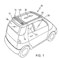
- a vehicle 10 with a folding roof 30 is shown, which in Opening or closing direction 32 slidably received in guide rails of which a front guide rail section 26 is floating in with the Vehicle 10 detachably connected side rails 28 is added.
- the folding roof 30 can be moved backwards in the opening direction 32 to such an extent that its Roof top 149 is essentially flush with a front edge of a roof cassette 12 completes and all movable parts of the folding roof 30 in one Guide rail section 22 of a closure device are received by the first embodiment, generally designated 14 in FIGS. 3 to 7 is illustrated.
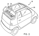
- the roof cassette 12 adjusts to a body-fixed one Counter bearing of the vehicle 10 can be fixed by means of the locking device 14 Roof part, which is articulated via a four-bar link, not shown Connected vehicle body and with the closure device 14 open the four-bar joint with foldable side parts 16 and a plastic rear window 18 comprehensive foldable rear section can be lowered.
- the locking device 14 on a Four-joint additional counter bearing can be set to the Hold the roof cassette in this position.
- the in Driving direction seen left locking device 14 is shown, but itself all explanations analogously to the mirror image right Obtain the locking device.
- the in Fig. 3 to 7 with X designated axis in the opening direction of the folding roof 30, i.e. in the same Direction as the arrow 32 pointing in the direction of the vehicle in FIG. 1 points.
- the two closure devices 14 are symmetrical to one in Vehicle longitudinal axis of symmetry inside the roof cassette 12 mounted near their side outer surfaces so that they are attached to the on the B-pillars 20 attached body-fixed counter bearings can be determined at the same time the guide rail sections 22 of the closure devices 14 in alignment with the front guide rail sections 26 of the side rails 28 be aligned by one fixed on the guide rail section 22 Alignment bar 24 as an alignment member in engagement with the front Guide rail sections 26 is brought.
- the closure device 14 comprises a bearing plate 34 with an as Recording groove 48 trained receiving member into which a bolt 46 of the of the B-pillar 20 attached counter bearing in the direction of displacement 50 (see FIG. 5) inserted and by means of a locking groove 42 of a locking hook 36 can be locked.
- the locking groove 42 is in a front arm 38 of the locking hook 36 is placed, which is pivotable about a bearing pin 56 in a bent bearing lever 58 is added.
- the bearing pin 56 of the Locking hook 36 is approximately in the middle between which the locking groove 42 comprising front arm 38 and a rear arm 40, the Locking hook 36 about the axis of the bearing pin 56 in the pivoting direction 44 (see Fig. 3) between one in Figs. 3, 5 and 6 shown locking and a release position is pivotable.
- Locking hook 36 also between one in Fig. 5 in broken lines reproduced front locking position 52 and a rear locking position 54 in Sliding direction 50 slidable.
- the bearing lever 58 is formed in two parts and comprises two in the Y direction Thickness of a sleeve 62 spaced congruent halves, the spacing so is dimensioned that the locking hook 36 and one described below Control lever 84 can be added between them.
- the socket 62 is open an axis 60 slid on the arm 64 of the bearing lever 58 in the Y direction enforced that it projects beyond the halves of the bearing lever 58 on both sides and on the one hand in the bearing plate 34 and on the other hand in an arm 64 encompassing bearing bracket 59 is held, which in turn on the bearing plate 34th is set.
- the bearing lever 58 is by means of one on its second arm 66 fixed control pin 68 pivotable about the axis 60, the control pin 68 protrudes beyond the bearing lever in the Y direction and into a control track 72 Switching slot 74 engages in which it is guided over a sliding block 70.
- the switching link 74 is integrated in a link body 80, the second Has shifting gate 78, in the control path 76 thereof on the control lever 84 fixed control pin 82 is slidably received and its Swiveling movement about the axis of the bearing pin 56 causes by means of Control lever 84 together with the locking hook 36 in the bearing lever 58 is mounted, the control lever in the direction of the front arm 38 of the Locking hook 36 extends.
- a bend 92 of the control lever 84 engages a recess 85 open in the Z direction of the locking hook 36 and serves to carry the locking hook 36 when the control lever 84 over its control pin 82 is pivoted clockwise by the control track 76 (The terms used clockwise and counterclockwise each refer to an observation in the Y direction).
- a holding lever 89 is pivotable approximately in the middle by a shoulder bolt 91 on the Locking hook 36 in the area between the recess 85 and the Locking groove 42 mounted, with a tension spring 90 between one on one first arm 93 of the holding lever 89 located projection 88 and a bend 86 of the control lever 84 is provided.
- the in first arm 93 of the holding lever 89 above a substantially in the X direction open locking area 98 arranged inclined surface 95 is formed such that about the prestressed contact of the inclined surface 95 on the retaining bolt 87 Force is exerted on the locking hook 36, the latter in Counterclockwise around the axis of the bearing pin 56 rotates, and the Locking hook 36 seen in the longitudinal direction of the vehicle 10 located behind the locking groove 42 (i.e., starting from the locking groove 42 offset in the positive X direction), 50 in the displacement direction extending sliding surface 190 rests on a bend 188 of the bearing plate 34.
- the Retaining pin 87 also serves as a catching device into which the latching area 98 of the Holding lever 89 engages when the locking hook 36 is in its Release position is.
- a second arm 94 of the holding lever 89 which is located below the shoulder bolt 91 (i.e., offset with respect to this in the negative Z direction), has an im projection 97 protruding substantially in the X direction, which in order to Control lever 84 set with respect to the locking hook 36 to one Bottom of the bend 92 of the control lever 84 can be applied as soon as the Locking hook 36 approaches its rear latching position 54.
- a total of 100, essentially in the X direction extending alignment plate is with the bearing plate 34 via a plurality of screws 99 connected, which is simultaneously a lower area of the guide rail section 22, which also has blind rivets (not shown) in its upper section Area is fixed directly to the bearing plate 34, with a solid cohesion achieved by bearing plate 34, guide rail section 22 and alignment plate 100 becomes.
- the guide rail section 22 has a lower and an upper slideway 101 or 102, which by a partition 104 extending in the X-Z plane are separated from each other.
- the lower slideway 101 is laterally from the partition 104 and a rear wall of the bearing plate 34 and up and down through Legs that extend from the partition 104 in the ⁇ Y direction, limited and open in +/- X direction.
- the link body 80 is in the +/- X direction slidable between a rear and a front end position.
- the slideway 102 is up and down by extending in the Y direction Limits 112 and 110 and by means of perpendicular to the legs 110 and 112 arranged webs 109 divided into at least two open chambers 111, 113, of which the inner chamber 111 of receiving a driving slider 114 and the outer chamber 113 serves to receive a roof glider 116.
- Both Gliders 114 and 116 can be moved in the +/- X direction, with the driving glider 114 a pressure-resistant cable 174 is attached, which is connected to the Roof cassette 12 fixed electric motor 222 (see FIG. 9) as part of an auxiliary actuator 220 is movable and is guided in a cable duct 118, which is received laterally next to the slideway 102 in the partition 104.
- a tactile slide 120 which can be displaced in the +/- X direction as part of a Counter bearing detection device added by the action of an intermediate the feeler 120 and the alignment plate 100 attached tension spring 122 in the ⁇ X direction is biased such that its stylus tip 124 has a leading edge 125 of the guide rail section 22 protrudes.
- a release 126 arranged with a release arm 128 of a bent locking lever 130 interacts, which in turn is pivotable about an axis 131 between the Bearing plate 34 and the alignment plate 100 is mounted.
- a locking lug 133 is provided, which is designed in a complementary shaped, not shown leading edge on the underside of the Link body 80 to engage when the link body 80 is in a behind warning position located in its front end position.
- the Warning position of the link body 80 with respect to the bearing plate 34 on a Place arranged between the front and rear end positions of the Link body 80 is located the front end position of a smaller X coordinate corresponds to the rear end position.
- the locking lever 130 is by means of a spring arm 134 a two spring arms 134 and 136 comprehensive combination spring 138 loaded counterclockwise, so that the Locking lug 133 biased when the link body 80 is in the warning position bears against its leading edge and prevents the link body 80 from being Front end position reached if the counter bearing is not in its target position Regarding the closure device 14 is located.
- the backdrop body is in this Fall only between its rear end position and its warning position.
- the second spring arm 136 of the Combi spring 138 is biased upwards in the Z direction and can counteract it Bias down from the rear arm 40 of the locking hook 36 be deflected when the locking hook 36 is in its release position located.
- the spring arm 136 is biased in its upward direction Home position actuated an electrical microswitch 140, which together with the Combination spring 138 is fixed to the bearing plate 34, the microswitch 140 being a Corresponding signal "locking hook in locking position" delivers.
- This The signal is used as an input variable in a motorized operation of the Electronic control 218 controlling closure device 14 (see FIG. 9) fed, which also control the motorized operation of the opening and Closing movement of the folding roof 30 takes over.
- the spring arm 136 instead of its resilient Preload upwards with the rear arm 40 of the To connect locking hook 36 so that the latter the spring arm 136 in both Directions, i.e., up and down, operated.
- the tactile glider 120 when Coupling process of the closure device 14 to the counter bearing from Side spar 28 operated and moved in the X direction so far that the Locking lug 133 of the locking lever 130 on the link body 80 no longer in its Warning position locked.
- the side rail 28 is removed from the vehicle or for some other reason it is not in its target position with respect to the locking device 14 in the coupling position, the probe tip 124 at Coupling process not operated or not operated far enough in the X direction and the Link body 80 locked when it reaches its warning position, even if that Counter bearing is in the target position.
- the counter bearing detection device used in principle for side post recognition. This has the further advantage that when coupling the closure device 14 to the further counter bearing, which is attached to the four-bar linkage, the link body 80 no further than into it Warning position can be moved, because that is at the four-bar linkage intended counter bearing is in solilage, but a side rail is not available is. This prevents the locking of the Rooftop glider 116 is released with respect to the closure device 14, when the locking device 14 is coupled to the counter bearing of the four-bar linkage becomes.
- An alignment fork 152 at a front end of the alignment plate 100 is used for Alignment of the closure device 14 in the Y and Z directions with respect to the front guide rail section 26, for which purpose the alignment fork 152 engages in a complementarily shaped alignment bearing, which is a unit with the front guide rail section 26 floating in the side rail 28 forms.
- the on the guide rail section 22 of the closure device 14 fixed alignment bar 24, which is in the Z direction above the alignment fork 152 is located and brought into engagement with the front guide rail section 26 prevents tilting around the X axis of the front Guide rail section 26 with respect to the guide rail section 22.
- An alignment surface 150 is on a side surface of the alignment fork 152 in the X-Z plane located and on the end face of the bolt 46 on the B-pillar 20th attached counter bearing so that in cooperation with the mirror-image right locking device and the right bolt one in the Y direction seen symmetrical alignment of the entire roof cassette 12 with Reference is made to the two body-fixed bolts 46.
- End position spring 146 which comprises two spring arms 142 and 144, one of which the spring arm 142 engages from below into the chamber 113 in which the Rooftop glider 116 is included, which with a rooftop 149 of the Folding roof 30 is connected and the opening and closing movement of the same causes.
- the second spring arm 144 is designed, an electrical microswitch 148 to operate mechanically when the Dachspitze glider 116 in a Stop position, the microswitch 148 the signal "Dachspitzeglider in Stop position "to the electronic control unit 218 (see FIG. 9).
- the rooftop glider 116 is fully in that position Guide rail section 22 of the closure device 14 and can be locked with respect to the guide rail section 22. With the Rooftop gliders 116 are all movable parts of the folding roof 30 in the Guide rail section 22 held and together with the roof cassette 12th be decoupled from the body-mounted counter bearing.
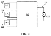
- the control 218 of the auxiliary actuator is obtained 220 next to the signals of one of two switch positions ("Open” and "Close") actuating switch 224 also have the signals two sensors 226 and 228 as input variables.
- the operation switch 224 is operated by the operator and serves to initiate both the opening and Closing movement of the folding roof as well as the coupling and uncoupling movement of the Locking device, i.e. the swiveling and sliding movements of the Locking hook.
- two actuation switches can be provided, one of which is the opening and closing movement of the folding roof and one of fully open folding roof the coupling and uncoupling movement of the Closing device initiates.
- the two sensors 226 and 228 are concerned in the case of the first embodiment of the closure device (shown in FIG the fig. 3 to 7) around the microswitches 148 and 140 8 described second embodiment of the
- the closure device is used as a sensor 228 instead of the microswitch 140 inductive sensor 216 used.
- the roof tip glider 116 and the Driving sliders 114 in the front guide rail section 26 and positively connected to one another by means of a locking block 164, in the Z direction is slidably received in the roof tip glider 116.
- the Roof cassette 12 is on the locking devices 14 on the B-pillars 20 of the Vehicle 10 fixed, the locking hook 36 in Locking position stops in its rear latching position 54.
- the backdrop body 80 is in its front end position and is in this in the Y direction Slidably mounted locking block 156, which by means of a compression spring 160 loaded ball 158 can be locked in its end positions, in a recess 162 Bearing plate 34 held.
- the control pin 82 is Control lever 84 in a holding area 206 of the control track 76 for the Pivoting movement of the locking hook 36 responsible shifting gate 78.
- Der Retaining lever 89 is by abutting its inclined surface 95 on the retaining bolt 87 pivoted counterclockwise so far that its projection 97 the bend 92 of the control lever 84 engages and this with reference to the Locking hook 36 sets.
- the locking hook 36 is ultimately in his Locked position blocked. So that the backdrop body 80 in its front End position must, of course, as described above Counter bearing or the side rail 28 are in the desired position, the feeler slide 120 is actuated and the locking tab 133 of the locking lever 130 disengaged with respect to that at the Underside of the link body 80 arranged leading edge.
- the folding roof 30 can be opened by the roof tip glider 116 in the opening direction 32 is moved behind.
- the sliding movement becomes the rooftop glider 116 impressed by the slider 114, which in turn by means of the known per se rigid cable 174 is moved over the electric motor 222, which in the Roof cassette 12 is added.
- Both the rooftop glider 116 and the Carriage gliders 114 eventually get from the front Guide rail section 26 in the guide rail section 22 of the Locking device 14, the roof tip glider 116 as soon as it is in its Stop position is reached, abuts a stop 168, which in the Guide rail section 22 is provided and a further displacement of the Rooftop glider 116 prevented to the rear (in the X direction) (see Fig. 7), wherein also as described above, the electrical microswitch 148 from the spring arm 144 is operated.
- the driving slider 114 now has its one shown in FIG. 7 Transfer position reached.
- the operator continues to operate the switch position "Opening" of the actuation switch 224, then at the control 218 applied signal "rooftop glider in stop position" of the microswitch 148 the Decoupling movement of the closure device initiated, namely preferably only after certain safety conditions have been met. For this can e.g. count that the vehicle may not be moved and / or that the Operator operates switch 224 during a predetermined actuation time must hold in the "Open" switch position.
- the entrainment slider 114 When the uncoupling process is initiated, the entrainment slider 114 first becomes from the electric motor 222 via the compression-resistant cable 174 with a force in the X direction applied so that an inclined surface 170 in the locking block 164th receiving recess 166 in the driving slider 114 a force in the Z direction exercises on the bolt 164, which is sufficient, the latter so far in the Z direction move the latch 164 out of engagement with respect to the recess 166 arrives in the driving glider 114 and with it the driving glider 114 opposite end into a recess 172 in the guide rail section 22 is pushed.
- the roof top glider 116 is thus positively in the Guide rail section held, and the driving slider 114 for another Displacement in the X direction is released, the roof tip glider 116 facing side of the driving slider 114 is designed so that a release of the Positive connection between the roof tip glider 116 and the Guide rail section 22 by moving the locking block 164 in Rooftop glider 116 in the ⁇ Z direction is excluded.
- the driving glider 114 comes by means of its Coupling surface 176 on the leading edge 108 of the in the front end position according to Fig.
- the Riegelstein 156 releases the positive connection of the link body 80 with the Bearing plate 34 and at the same time forms one between the link body 80 and the driving glider 114, which the link body 80 in the direction of which rear end position.
- the driving glider 114 moves the link body 80 in takes its rear end position in the X direction over the coupling surface 176, which abuts the contact surface (leading edge 108).
- the entrainment of the backdrop body 80 in the direction of its front end position (in the X direction) is carried out by means of the Positive connection between the driving glider 114 and the link body 80, which was effected via the brick 156.
- the locking block 156 can only in its end position shown in FIG. 7 be locked by means of the spring-loaded ball 158.
- the front detent position is 52 reached when the sliding block 70 is in the lowest point of the ramp-shaped Sliding area 208 of the control path is located and in a front stopping area 212 merges, in which it is guided essentially horizontally, so that the Bearing lever 58 no longer pivots.
- the microswitch 140 is actuated and delivers as Sensor 228 of controller 218 receives the input signal "locking hook in Locking position ".
- the controller 218 triggers the automatic closing movement of the locking hook 36 by the Electric motor 222 controls, which in turn the displacement of the link body 80 actuated towards its front end position.
- the take-along glider 114 the electric motor 222 continues to apply a force in the vomX direction, which has the consequence that the locking block 156 of an inclined surface 182 in the Recess 180 of the driving glider 114 in the ⁇ Y direction into the recess 162 in the bearing plate 34 is shifted and at the same time the driving slider 114 from Link body 80 is released.
- the locking block 156 is made by the compression spring 160 loaded ball 158 held in this position, and the automatic The closing device 14 is closed by switching off the Electric motor 222 ended.
- the electric motor 222 is reactivated and moves the slider 114 further forward into the transfer position, where it is connected by means of a coupling surface 184 comes to rest on the rooftop glider 116. It is about compression-resistant cable 174 on the rooftop glider 116 a force forward exercised, sufficient over an inclined surface 186 on a front of the Recess 172 in the guide rail section 22 the locking block 164 of the Rooftop glider 116 in the -Z direction out of the recess 172 and into the To push recess 166 of the driving slider 114 into it.
- FIGS. 3 to 7 shows an alternative embodiment of a closure device illustrates which differs from that shown in FIGS. 3 to 7 reproduced in essentially differs only in that on a holding lever accordingly the holding lever 89 of the first embodiment is omitted and a Locking hook 192 does not have a rear arm corresponding to rear arm 40 of the locking hook 36.
- the resilient bias of the Locking hook 192 in the direction of its locking position is by a tension spring 196 applied, which is between a bend 194 on Locking hook 192 and a retaining lug 198 extends to the bearing plate 34.
- a modified control lever 200 instead of the control pin 82 des Control lever 84 integrally formed on the control lever 200 Control flap 202, which interacts with the control path 76 to the To control pivoting movement of the locking hook 192.
- the fold 92 of the Control lever 200 is located, as is the control lever 84 of the first Embodiment of the closure device is the case, clockwise pretensioned from below on the locking hook 192, but the Biasing force in the second embodiment according to FIG. 8 from the tension spring 90 which, in contrast to the first embodiment, is located between the Bend 86 on the control lever 200 and the bend 194 on the locking hook 192 extends.
- the inductive sensor 216 used which is actuated by the bolt 46 of the counter bearing, when the bolt 46 is in a position within the receiving groove 48, in which he of the locking groove 42 of the in the front locking position 52nd located locking hook 192 can be locked. Whether the locking hook 192 is actually pivoted back into the locking position, is by the inductive sensor 216, which instead of the microswitch 140 as sensor 228 on the Controller 218 is connected, not detected. However, this should not be the case the closing movement of the locking hook 192 will not be on the Transfer counter bearing so that it does not reach the solilayer and the probe tip 124 of the principle also in the second embodiment of the closure device counter bearing detection device adopted unchanged or not is operated far enough in the X direction.
- the counter bearing detection device blocks the link body 80 when reached in the manner already described the warning position, whereupon the electric motor 222 is also blocked.
- This one recognizes the controller 218 and deactivates the electric motor 222 Situation "link body in warning position", which is equivalent to “counter bearing is not in the desired position ", is advantageously displayed to the operator, so that this by pressing the "Open” switch position of the switch again 224 decouples the locking device again from the counter-bearing to a new one Make coupling process.
Landscapes
- Engineering & Computer Science (AREA)
- Mechanical Engineering (AREA)
- Lock And Its Accessories (AREA)
- Fittings On The Vehicle Exterior For Carrying Loads, And Devices For Holding Or Mounting Articles (AREA)
Abstract
Description
- Fig. 1
- eine perspektivische Darstellung eines Fahrzeugs mit einem als Dachkassette ausgebildeten Dachteil, welches Teil eines Faltdachs ist und mittels einer Verschlussvorrichtung an einem an einer B-Säule des Fahrzeugs befestigten Gegenlager festgelegt ist, wobei das Faltdach sich in seiner geöffneten Position befindet;
- Fig. 2
- eine perspektivische Darstellung ähnlich der Fig. 1, wobei die Dachkassette mitsamt den verschiebbaren Teilen des Faltdachs in eine Ablageposition abgesenkt ist;
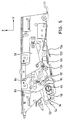
- Fig. 3
- eine perspektivische Darstellung der Verschlussvorrichtung, wobei sich ein Verriegelungshaken derselben in seiner hinteren Rastposition in Verriegelungsstellung befindet;
- Fig. 4
- eine Explosionsdarstellung der Verschlussvorrichtung der Fig. 3;
- Fig. 5
- eine Seitenansicht in Richtung auf eine Lagerplatte der Verschlussvorrichtung der Fig. 3;
- Fig. 6
- eine Seitenansicht in Richtung auf eine Führungsschiene der Verschlussvorrichtung der Fig. 3;
- Fig. 7
- einen schematischen Teilschnitt entlang der Linie VII-VII der Fig. 3, der in Prinzipdarstellung die Riegelsteinankopplungen eines motorisch verschiebbaren Mitnahmegleiters an einen die Bewegung des Verriegelungshakens der Verschlussvorrichtung steuernden Kulissenkörper sowie an einen Dachspitzengleiter des Faltdachs veranschaulicht;
- Fig. 8
- eine perspektivische Darstellung einer abgewandelten Ausführungsform einer Verschlussvorrichtung, wobei sich ein Verriegelungshaken derselben in seiner hinteren Rastposition in Verriegelungsstellung befindet; und
- Fig. 9
- ein Prinzipschaltbild einer Steuerung der Verschlussvorrichtung.
- 10
- Fahrzeug
- 12
- Dachkassette
- 14
- Verschlussvorrichtung
- 16
- Seitenteil
- 18
- Heckscheibe
- 20
- B-Säule
- 22
- Führungsschienenabschnitt
- 24
- Ausrichtleiste
- 26
- vorderer Führungsschienenabschitt
- 28
- Seitenholm
- 30
- Faltdach
- 32
- Öffnungs- bzw. Schließrichtung
- 34
- Lagerplatte
- 36
- Verriegelungshaken
- 38
- vorderer Arm (von 36)
- 40
- hinterer Arm (von 36)
- 42
- Verrieglungsnut
- 44
- Schwenkrichtung
- 46
- Bolzen
- 48
- Aufnahmenut
- 50
- Verschieberichtung
- 52
- vordere Rastposition
- 54
- hintere Rastposition
- 56
- Lagerstift
- 58
- Lagerhebel
- 59
- Lagerbügel
- 60
- Achse (von 58)
- 62
- Buchse (von 58)
- 64, 66
- Arm (von 58)
- 68
- Steuerstift
- 70
- Gleitstein
- 72
- Steuerbahn
- 74
- Schaltkulisse
- 76
- Steuerbahn
- 78
- Schaltkulisse
- 80
- Kulissenkörper
- 82
- Steuerbolzen
- 84
- Steuerhebel
- 85
- Ausnehmung (von 36)
- 86
- Abkantung (von 84 bzw. 200)
- 87
- Haltebolzen
- 88
- Vorsprung (von 89)
- 89
- Haltehebel
- 90
- Zugfeder
- 91
- Ansatzbolzen
- 92
- Abkantung (von 84 bzw. 200)
- 93
- erster Arm (von 89)
- 94
- zweiter Arm (von 89)
- 95
- Schrägfläche
- 97
- Vorsprung
- 98
- Rastbereich
- 99
- Schraube
- 100
- Ausrichtplatte
- 101, 102
- Gleitbahn
- 104
- Trennwand
- 106
- Durchbruch
- 108
- Anlaufkante
- 109
- Steg
- 110, 112
- Schenkel
- 111, 113
- Kammer
- 114
- Mitnahmegleiter
- 116
- Dachspitzengleiter
- 118
- Kabelkanal
- 119
- Oberseite
- 120
- Tastgleiter
- 122
- Zugfeder
- 124
- Tastspitze
- 125
- Vorderkante
- 126
- Ausrücker
- 128
- Ausrückarm
- 130
- Sperrhebel
- 131
- Achse
- 132
- Arm (von 130)
- 133
- Sperrnase
- 134, 136
- Federarm
- 138
- Kombifeder
- 140
- Mikroschalter
- 142, 144
- Federarm
- 146
- Enlagenfeder
- 148
- Mikroschalter
- 149
- Dachsitze
- 150
- Ausrichtfläche
- 152
- Ausrichtgabel
- 156
- Riegelstein
- 158
- Kugel
- 160
- Druckfeder
- 162
- Aussparung
- 164
- Riegelstein
- 166
- Aussparung
- 168
- Anschlag
- 170
- Schrägfläche
- 172
- Aussparung
- 174
- drucksteifes Kabel
- 176
- Koppelfläche
- 178
- Schrägfläche
- 180
- Aussparung
- 182
- Schrägfläche
- 184
- Koppelfläche
- 186
- Schrägfläche
- 188
- Abkantung
- 190
- Gleitfläche
- 192
- Verriegelungshaken
- 194
- Abkantung
- 196
- Zugfeder
- 198
- Haltenase
- 200
- Steuerhebel
- 202
- Steuerlappen
- 204, 206
- Haltebereich
- 208
- Verschiebebereich
- 210
- Schwenknocke
- 212
- Haltebereich
- 214
- Schrägfläche
- 216
- induktiver Sensor
- 218
- Steuerung
- 220
- Hilfskraft-Betätigungsvorrichtung
- 222
- Elektromotor
- 224
- Betätigungsschalter
- 226, 228
- Sensor
Claims (16)
- Verschlussvorrichtung zur lösbaren Festlegung eines Dachteils (Dachkassette 12) eines Fahrzeugs (10) an einem karosseriefesten Gegenlager, wobei die Verschlussvorrichtung einen in eine Freigabestellung bringbaren Verriegelungshaken (36, 192) zum Verriegeln des Gegenlagers wenigstens in einer vorderen (52) und einer hinteren (54) Rastposition des Verriegelungshakens (36, 192) sowie einen Sensor (216, 228, Mikroschalter 140) umfasst, mittels dem eine von einer Hilfskraft-Betätigungsvorrichtung (220) bewirkbare Zuziehbewegung des Verriegelungshakens (36, 192) in Richtung auf seine hintere Rastposition (54) aktivierbar ist, dadurch gekennzeichnet, dass der Verriegelungshaken (36, 192) in seiner vorderen Rastposition (52) von der Freigabestellung in eine Verriegelungsstellung bringbar ist, wobei der Sensor (Mikroschalter 140, 216, 228) in der vorderen Rastposition (52) des Verriegelungshakens (36, 192) bei verriegeltem Gegenlager betätigbar ist und an ihm ein Aktivierungssignal anliegt, welches in Signalverbindung mit einer Steuerung (218) steht, die ihrerseits die Zuziehbewegung des Verriegelungshakens (36, 192) nach Anliegen des Aktivierungssignals auslöst.
- Verschlussvorrichtung nach Anspruch 1, dadurch gekennzeichnet, dass die Verschlussvorrichtung ferner eine Lagerplatte (34) mit einem Aufnahmeorgan (Aufnahmenut 48) für das Gegenlager umfasst, wobei das Gegenlager mit Bezug auf das Aufnahmeorgan (Aufnahmenut 48) verriegelbar und im wesentlichen linear verschiebbar ist.
- Verschlussvorrichtung nach Anspruch 2, dadurch gekennzeichnet, dass der Verriegelungshaken (36, 192) im wesentlichen in Verschieberichtung (50) des Gegenlagers zwischen der vorderen (52) und der hinteren (54) Rastposition verschiebbar sowie im wesentlichen senkrecht hierzu zwischen der Verriegelungs- und der Freigabestellung schwenkbar ist.
- Verschlussvorrichtung nach einem der Ansprüche 1 bis 3, dadurch gekennzeichnet, dass die Betätigung des Sensors (228, Mikroschalter 140) durch Wechselwirkung desselben mit dem in seiner vorderen Rastposition (52) in Verriegelungsstellung befindlichen Verriegelungshaken (36) erfolgt.
- Verschlussvorrichtung nach Anspruch 4 rückbezogen auf Anspruch 3, dadurch gekennzeichnet, dass der Verriegelungshaken (36) über seinen Drehpunkt hinaus verlängert ist und einen hinteren Arm (40) aufweist, der die Betätigung des Sensors (228, Mikroschalter 140) bewirkt.
- Verschlussvorrichtung nach Anspruch 5, dadurch gekennzeichnet, dass der hintere Arm (40) des Verriegelungshakens (36) den Sensor (228, Mikroschalter 140) mittelbar über einen Federarm (136) einer Feder (Kombifeder 138) betätigt, wobei der Sensor (228, Mikroschalter 140) und die Feder (Kombifeder 138) an der Lagerplatte (34) festgelegt sind.
- Verschlussvorrichtung nach einem der Ansprüche 1 bis 3, dadurch gekennzeichnet, dass die Betätigung des Sensors (216, 228) durch Wechselwirkung desselben mit dem Gegenlager erfolgt, welches in der Verschlussvorrichtung bei in vorderer Rastposition (52) befindlichem Verriegelungshaken (192) von diesem verriegelt ist.
- Verschlussvorrichtung nach einem der vorhergehenden Ansprüche, dadurch gekennzeichnet, dass der Sensor (228) als mechanisch betätigbarer taktiler Sensor (Mikroschalter 140) ausgebildet ist.
- Verschlussvorrichtung nach einem der Ansprüche 1 bis 7, dadurch gekennzeichnet, dass der Sensor (228) als berührungslos arbeitender Näherungssensor (216) ausgebildet ist.
- Verschlussvorrichtung nach einem der vorhergehenden Ansprüche, dadurch gekennzeichnet, dass der Sensor (228, Mikroschalter 140) im wesentlichen in jeder Position des Verriegelungshakens (36) zwischen der vorderen (52) und der hinteren (54) Rastposition betätigbar ist.
- Verschlussvorrichtung nach einem der vorhergehenden Ansprüche, gekennzeichnet durch eine Gegenlagererkennungseinrichtung, mittels der bei Außersolllage des Gegenlagers die Zuziehbewegung des Verriegelungshakens (36, 192) vor Erreichen seiner hinteren Rastposition (54) blockierbar ist.
- Verschlussvorrichtung nach einem der Ansprüche 3 bis 11, dadurch gekennzeichnet, dass die Verschiebebewegung und die Schwenkbewegung des Verriegelungshakens (36, 192) von Schaltkulissen (74, 78) gesteuert werden, die in einem gemeinsamen Kulissenkörper (80) integriert sind, der in einem an der Verschlussvorrichtung festgelegten Führungsschienenabschnitt (22) verschiebbar aufgenommen ist.
- Verschlussvorrichtung nach Anspruch 12, dadurch gekennzeichnet, dass die Hilfskraft-Betätigungsvorrichtung (220) einen Elektromotor (222) umfasst, der die Verschiebung des Kulissenkörpers (80) bewirkt.
- Verschlussvorrichtung nach Anspruch 12 oder 13, dadurch gekennzeichnet, dass es sich bei dem Dachteil um eine Dachkassette (12) handelt, die Teil eines Falt- (30) oder Lamellendaches ist, wobei öffnungsfähige Teile des Falt- (30) oder Lamellendachs in dem Führungsschienenabschnitt (22) der Verschlussvorrichtung aufnehmbar und mit Bezug auf den Führungsschienenabschnitt (22) arretierbar sind.
- Verschlussvorrichtung nach Anspruch 14, dadurch gekennzeichnet, dass der Elektromotor (222) eine Verschiebung eines Dachspitzengleiters (116) bewirkt, der mit einem vorderen Ende des Falt- (30) oder Lamellendachs verbundenen ist und dessen Öffnungs- und Schließbewegung bewirkt, wobei der Dachspitzengleiter (116) in dem Führungsschienenabschnitt (22) aufnehmbar und in einer Halteposition arretierbar ist.
- Verschlussvorrichtung nach Anspruch 15, dadurch gekennzeichnet, dass der Dachspitzengleiter (116) in seiner Halteposition einen Sensor (226, Mikroschalter 148) betätigt, der in Signalverbindung mit der Steuerung (218) steht.
Applications Claiming Priority (2)
| Application Number | Priority Date | Filing Date | Title |
|---|---|---|---|
| DE1999127236 DE19927236C1 (de) | 1999-06-15 | 1999-06-15 | Verschlußvorrichtung |
| DE19927236 | 1999-06-15 |
Publications (3)
| Publication Number | Publication Date |
|---|---|
| EP1060926A2 true EP1060926A2 (de) | 2000-12-20 |
| EP1060926A3 EP1060926A3 (de) | 2001-10-31 |
| EP1060926B1 EP1060926B1 (de) | 2006-06-07 |
Family
ID=7911291
Family Applications (1)
| Application Number | Title | Priority Date | Filing Date |
|---|---|---|---|
| EP20000112526 Expired - Lifetime EP1060926B1 (de) | 1999-06-15 | 2000-06-13 | Verschlussvorrichtung |
Country Status (4)
| Country | Link |
|---|---|
| EP (1) | EP1060926B1 (de) |
| JP (1) | JP2001032595A (de) |
| DE (2) | DE19927236C1 (de) |
| ES (1) | ES2263413T3 (de) |
Cited By (2)
| Publication number | Priority date | Publication date | Assignee | Title |
|---|---|---|---|---|
| GB2385092A (en) * | 2002-02-07 | 2003-08-13 | Webasto Vehicle Sys Int Gmbh | Interlocking device for the folding roof of a motor vehicle having a covertible or soft top design |
| US12304288B2 (en) | 2023-06-12 | 2025-05-20 | Ford Global Technologies, Llc | Sealing system for vehicle closure system |
Families Citing this family (8)
| Publication number | Priority date | Publication date | Assignee | Title |
|---|---|---|---|---|
| DE10121858A1 (de) * | 2001-05-06 | 2002-11-14 | Cts Fahrzeug Dachsysteme Gmbh | Verriegelungseinrichtung für ein verstellbares Dachteil in einem Fahrzeugdach |
| DE10300882B4 (de) * | 2003-01-13 | 2005-07-21 | Dr.Ing.H.C. F. Porsche Ag | Verdeckverschluss eines Fahrzeugs |
| DE10352489B3 (de) * | 2003-11-07 | 2005-07-07 | Ise Industries Gmbh | Kraftunterstützter Verschluß für Verdecke, Klappen oder dergleichen an Fahrzeugen |
| DE102004005644A1 (de) * | 2004-02-04 | 2005-09-08 | Ise Industries Gmbh | Verschluss für Verdecke, insbesondere für einen Stoffhaltebügel eines Verdecks |
| DE102004017327B4 (de) * | 2004-04-06 | 2008-09-25 | Webasto Ag | Verschlußvorrichung zum lösbaren Festlegen eines Dachteils eines Fahrzeugs |
| DE102005001079B4 (de) * | 2005-01-08 | 2006-09-21 | Webasto Ag | Verriegelungsvorrichtung für ein Fahrzeugteil |
| DE102006041794A1 (de) * | 2006-09-06 | 2008-03-27 | Webasto Ag | Rolloanordnung für ein Kraftfahrzeug |
| DE102012108531B4 (de) | 2012-09-12 | 2019-01-24 | Webasto-Edscha Cabrio GmbH | Cabriolet-Verdeck mit Verschlusseinheit |
Citations (5)
| Publication number | Priority date | Publication date | Assignee | Title |
|---|---|---|---|---|
| DE1505721A1 (de) | 1966-04-16 | 1970-07-02 | Daimler Benz Ag | Vorrichtung zur Verriegelung eines Kraftfahrzeug-Klappverdecks |
| EP0492006A1 (de) | 1990-12-22 | 1992-07-01 | Design + Technik Gmbh | Vorrichtung zum Niederholen des freien Endes eines Fahrzeugverdecks oder dergleichen |
| DE4111646A1 (de) | 1991-04-10 | 1992-10-15 | Bayerische Motoren Werke Ag | Verriegelungseinrichtung, insbesondere fuer ein cabrio-faltverdeck |
| DE19634898A1 (de) | 1996-07-19 | 1998-01-22 | Kiekert Ag | Einrichtung zum Verschließen und zum Zuziehen sowie zum Öffnen der Heckraumklappe eines Kraftfahrzeuges |
| DE29703603U1 (de) | 1997-02-28 | 1998-06-25 | Wilhelm Karmann GmbH, 49084 Osnabrück | Verschlußvorrichtung für ein Cabriolet-Verdeck |
Family Cites Families (2)
| Publication number | Priority date | Publication date | Assignee | Title |
|---|---|---|---|---|
| JPH06104420B2 (ja) * | 1988-12-23 | 1994-12-21 | マツダ株式会社 | 自動車のキャンバストップ制御装置 |
| US5284378A (en) * | 1992-11-16 | 1994-02-08 | Wickes Manufacturing Company | Self-storing convertible top latch system |
-
1999
- 1999-06-15 DE DE1999127236 patent/DE19927236C1/de not_active Expired - Fee Related
-
2000
- 2000-06-13 DE DE50012886T patent/DE50012886D1/de not_active Expired - Fee Related
- 2000-06-13 ES ES00112526T patent/ES2263413T3/es not_active Expired - Lifetime
- 2000-06-13 EP EP20000112526 patent/EP1060926B1/de not_active Expired - Lifetime
- 2000-06-15 JP JP2000179575A patent/JP2001032595A/ja active Pending
Patent Citations (5)
| Publication number | Priority date | Publication date | Assignee | Title |
|---|---|---|---|---|
| DE1505721A1 (de) | 1966-04-16 | 1970-07-02 | Daimler Benz Ag | Vorrichtung zur Verriegelung eines Kraftfahrzeug-Klappverdecks |
| EP0492006A1 (de) | 1990-12-22 | 1992-07-01 | Design + Technik Gmbh | Vorrichtung zum Niederholen des freien Endes eines Fahrzeugverdecks oder dergleichen |
| DE4111646A1 (de) | 1991-04-10 | 1992-10-15 | Bayerische Motoren Werke Ag | Verriegelungseinrichtung, insbesondere fuer ein cabrio-faltverdeck |
| DE19634898A1 (de) | 1996-07-19 | 1998-01-22 | Kiekert Ag | Einrichtung zum Verschließen und zum Zuziehen sowie zum Öffnen der Heckraumklappe eines Kraftfahrzeuges |
| DE29703603U1 (de) | 1997-02-28 | 1998-06-25 | Wilhelm Karmann GmbH, 49084 Osnabrück | Verschlußvorrichtung für ein Cabriolet-Verdeck |
Cited By (4)
| Publication number | Priority date | Publication date | Assignee | Title |
|---|---|---|---|---|
| GB2385092A (en) * | 2002-02-07 | 2003-08-13 | Webasto Vehicle Sys Int Gmbh | Interlocking device for the folding roof of a motor vehicle having a covertible or soft top design |
| US6834907B2 (en) | 2002-02-07 | 2004-12-28 | Webasto Vehicle Systems International Gmbh | Interlocking device for the folding roof of a motor vehicle |
| GB2385092B (en) * | 2002-02-07 | 2005-09-21 | Webasto Vehicle Sys Int Gmbh | Interlocking device for the folding roof of a motor vehicle |
| US12304288B2 (en) | 2023-06-12 | 2025-05-20 | Ford Global Technologies, Llc | Sealing system for vehicle closure system |
Also Published As
| Publication number | Publication date |
|---|---|
| DE50012886D1 (de) | 2006-07-20 |
| EP1060926A3 (de) | 2001-10-31 |
| EP1060926B1 (de) | 2006-06-07 |
| JP2001032595A (ja) | 2001-02-06 |
| ES2263413T3 (es) | 2006-12-16 |
| DE19927236C1 (de) | 2000-10-12 |
Similar Documents
| Publication | Publication Date | Title |
|---|---|---|
| EP1060923B1 (de) | Fahrzeugdach | |
| EP1112881B1 (de) | Verriegelungsvorrichtung für ein Klappverdeck | |
| EP0727331B1 (de) | Fahrzeugdach mit zwei Deckelelementen | |
| DE19608916C1 (de) | Fahrzeugdach mit einer Folge von ausstellbaren Deckelelementen | |
| DE102006012062B4 (de) | Schließeinrichtung für einen Deckel eines Kraftwagens | |
| DE19513971C2 (de) | Fahrzeug-Sonnendach und Verfahren zur Steuerung eines solchen Daches | |
| DE19927236C1 (de) | Verschlußvorrichtung | |
| EP3550102B1 (de) | Baugruppe für eine gebäudetür mit einer dichteinheit und einer verriegelungseinrichtung | |
| WO2000079086A1 (de) | Sperrvorrichtung und damit versehene torantriebsvorrichtung für ein mittels eines motorantriebsaggregats antreibbares tor | |
| DE4321099A1 (de) | Belüftungseinrichtung für Fenster oder Türen | |
| DE19938378C2 (de) | Vorrichtung zum Öffnen und Verschließen einer Öffnung in einer Wandung mittels einer Schiebetür | |
| DE69901229T2 (de) | Kraftfahrzeugtürschloss | |
| DE4329580C1 (de) | Fahrzeugdach mit einer Folge von Lamellen | |
| DE19943713C1 (de) | In einem Führungsabschnitt verschiebbar aufgenommener Gleiter | |
| DE19951289A1 (de) | Sperrvorrichtung und damit versehene Torantriebsvorrichtung für ein mittels eines Motorantriebsaggregats antreibbares Tor | |
| DE19529702C1 (de) | Fahrzeugdach mit einer Folge von ausstellbaren Lamellen | |
| DE19927235C1 (de) | Verschlußvorrichtung | |
| DE202009012289U1 (de) | Elektronisches Verschlusssystem für Schränke mit einer im Schrankinneren angeordneten elektromotorisch gesteuerten Verriegelungsmechanik | |
| EP1767737A2 (de) | Torantrieb mit Aufschubsicherung | |
| DE102013212515B4 (de) | Türanlage | |
| DE102004036655A1 (de) | Vorrichtung zum automatischen Schließen einer Fahrzeugtür | |
| DE19529522C1 (de) | Fahrzeugdach mit einer Folge von ausstellbaren Lamellen | |
| DE102004005755B3 (de) | Öffnungsfähiges Fahrzeugdach | |
| DE102011084772B4 (de) | Antriebssystem für einen Deckel eines Kraftfahrzeug-Dachsystems | |
| EP2754801A2 (de) | Gegenkasten oder Einsteckschloss |
Legal Events
| Date | Code | Title | Description |
|---|---|---|---|
| PUAI | Public reference made under article 153(3) epc to a published international application that has entered the european phase |
Free format text: ORIGINAL CODE: 0009012 |
|
| AK | Designated contracting states |
Kind code of ref document: A2 Designated state(s): AT BE CH CY DE DK ES FI FR GB GR IE IT LI LU MC NL PT SE Kind code of ref document: A2 Designated state(s): DE ES FR IT |
|
| AX | Request for extension of the european patent |
Free format text: AL;LT;LV;MK;RO;SI |
|
| PUAL | Search report despatched |
Free format text: ORIGINAL CODE: 0009013 |
|
| AK | Designated contracting states |
Kind code of ref document: A3 Designated state(s): AT BE CH CY DE DK ES FI FR GB GR IE IT LI LU MC NL PT SE |
|
| AX | Request for extension of the european patent |
Free format text: AL;LT;LV;MK;RO;SI |
|
| 17P | Request for examination filed |
Effective date: 20020424 |
|
| AKX | Designation fees paid |
Free format text: DE ES FR IT |
|
| GRAP | Despatch of communication of intention to grant a patent |
Free format text: ORIGINAL CODE: EPIDOSNIGR1 |
|
| GRAS | Grant fee paid |
Free format text: ORIGINAL CODE: EPIDOSNIGR3 |
|
| GRAA | (expected) grant |
Free format text: ORIGINAL CODE: 0009210 |
|
| AK | Designated contracting states |
Kind code of ref document: B1 Designated state(s): DE ES FR IT |
|
| REF | Corresponds to: |
Ref document number: 50012886 Country of ref document: DE Date of ref document: 20060720 Kind code of ref document: P |
|
| RAP2 | Party data changed (patent owner data changed or rights of a patent transferred) |
Owner name: WEBASTO AG |
|
| REG | Reference to a national code |
Ref country code: ES Ref legal event code: FG2A Ref document number: 2263413 Country of ref document: ES Kind code of ref document: T3 |
|
| ET | Fr: translation filed | ||
| PLBE | No opposition filed within time limit |
Free format text: ORIGINAL CODE: 0009261 |
|
| STAA | Information on the status of an ep patent application or granted ep patent |
Free format text: STATUS: NO OPPOSITION FILED WITHIN TIME LIMIT |
|
| 26N | No opposition filed |
Effective date: 20070308 |
|
| PGFP | Annual fee paid to national office [announced via postgrant information from national office to epo] |
Ref country code: DE Payment date: 20090615 Year of fee payment: 10 |
|
| PGFP | Annual fee paid to national office [announced via postgrant information from national office to epo] |
Ref country code: FR Payment date: 20100706 Year of fee payment: 11 Ref country code: ES Payment date: 20100628 Year of fee payment: 11 |
|
| PGFP | Annual fee paid to national office [announced via postgrant information from national office to epo] |
Ref country code: IT Payment date: 20100626 Year of fee payment: 11 |
|
| PG25 | Lapsed in a contracting state [announced via postgrant information from national office to epo] |
Ref country code: DE Free format text: LAPSE BECAUSE OF NON-PAYMENT OF DUE FEES Effective date: 20110101 |
|
| PG25 | Lapsed in a contracting state [announced via postgrant information from national office to epo] |
Ref country code: IT Free format text: LAPSE BECAUSE OF NON-PAYMENT OF DUE FEES Effective date: 20110613 |
|
| REG | Reference to a national code |
Ref country code: FR Ref legal event code: ST Effective date: 20120229 |
|
| PG25 | Lapsed in a contracting state [announced via postgrant information from national office to epo] |
Ref country code: FR Free format text: LAPSE BECAUSE OF NON-PAYMENT OF DUE FEES Effective date: 20110630 |
|
| REG | Reference to a national code |
Ref country code: ES Ref legal event code: FD2A Effective date: 20121116 |
|
| PG25 | Lapsed in a contracting state [announced via postgrant information from national office to epo] |
Ref country code: ES Free format text: LAPSE BECAUSE OF NON-PAYMENT OF DUE FEES Effective date: 20110614 |