EP1060976A1 - Stossfänger mit bewegbarem Untersatz - Google Patents
Stossfänger mit bewegbarem Untersatz Download PDFInfo
- Publication number
- EP1060976A1 EP1060976A1 EP00401719A EP00401719A EP1060976A1 EP 1060976 A1 EP1060976 A1 EP 1060976A1 EP 00401719 A EP00401719 A EP 00401719A EP 00401719 A EP00401719 A EP 00401719A EP 1060976 A1 EP1060976 A1 EP 1060976A1
- Authority
- EP
- European Patent Office
- Prior art keywords
- flap
- vehicle
- shield
- shield according
- fact
- Prior art date
- Legal status (The legal status is an assumption and is not a legal conclusion. Google has not performed a legal analysis and makes no representation as to the accuracy of the status listed.)
- Granted
Links
Images



Classifications
-
- B—PERFORMING OPERATIONS; TRANSPORTING
- B62—LAND VEHICLES FOR TRAVELLING OTHERWISE THAN ON RAILS
- B62D—MOTOR VEHICLES; TRAILERS
- B62D35/00—Vehicle bodies characterised by streamlining
- B62D35/005—Front spoilers
-
- Y—GENERAL TAGGING OF NEW TECHNOLOGICAL DEVELOPMENTS; GENERAL TAGGING OF CROSS-SECTIONAL TECHNOLOGIES SPANNING OVER SEVERAL SECTIONS OF THE IPC; TECHNICAL SUBJECTS COVERED BY FORMER USPC CROSS-REFERENCE ART COLLECTIONS [XRACs] AND DIGESTS
- Y02—TECHNOLOGIES OR APPLICATIONS FOR MITIGATION OR ADAPTATION AGAINST CLIMATE CHANGE
- Y02T—CLIMATE CHANGE MITIGATION TECHNOLOGIES RELATED TO TRANSPORTATION
- Y02T10/00—Road transport of goods or passengers
- Y02T10/80—Technologies aiming to reduce greenhouse gasses emissions common to all road transportation technologies
- Y02T10/82—Elements for improving aerodynamics
Definitions
- the present invention relates to a bumper motor vehicle shield lower mobile.
- the shield extends over a height average which corresponds to a compromise between sufficient ground clearance and a certain limitation of air flow.
- French deflector FR-A-2 540 813 describes a deflector comprising a pivoting screen, provided with a spout on its leading edge, the incident air coming to press on this beak to cause the rotation of the screen.
- the invention achieves this by virtue of the fact that the shield includes a pressure above the flap.
- the presence of the pressure chamber above the flap in the shield according to the invention avoids having to make a flap having a spout on its leading edge, the tilting of the flap being partly due not negligible at the air pressure on the flap other than at its leading edge.
- the leading edge can thus be produced without a spout, unlike aforementioned front deflectors.
- the shield according to the invention can take two configurations, namely a so-called low speed configuration in which its movable flap is placed in position high, preferably at least partially retracted behind the shield, so that the lower edge of the shield is at the same height or even higher than the shields of traditional vehicles and a so-called high speed configuration in which the flap extends downwards, extending the shield so as to increase its surface useful and limit the air circulation under the vehicle.
- a so-called low speed configuration in which its movable flap is placed in position high, preferably at least partially retracted behind the shield, so that the lower edge of the shield is at the same height or even higher than the shields of traditional vehicles
- a so-called high speed configuration in which the flap extends downwards, extending the shield so as to increase its surface useful and limit the air circulation under the vehicle.
- the lift of the vehicle can be reduced at high speed, which improves its aerodynamic performance both in terms of its drag, which results in a reduction in engine consumption, as regards its lift, which leads to an improvement in the road behavior of the vehicle.
- the high ground clearance of the shield allows overcome common obstacles such as speed bumps, curbs and others frequent obstacles in city traffic or driving on roads not passable to the countryside.
- the shield according to the invention it can moreover be provided that in position high, the shield is at a height even higher than that of the shields traditional since the air screen function is useless as long as the vehicle is moving slowly.
- the shield comprises at least one air outlet opening on the pressure chamber.
- the flap is arranged so as to allow the creation of a depression below it when the vehicle is moving, in addition to the overpressure created by its upper side thanks to the pressure chamber.
- the flap may in particular have an inverted plane wing profile.
- the flap has a shaped leading edge to register in continuity with the lower edge of the shield when the vehicle is stationary, so as to extend the curve thereof.
- the leading edge of the flap advantageously consists of a piece added, which makes it easy to adapt to the aesthetics and style of vehicles.
- the flap may have a flexible rear part allowing a certain angular movement under the action of pressure differences above and below from it when the vehicle is moving.
- Such angular travel is for example between 5 and 10 °, being of preferably around 7 °.
- the aforementioned rear part is advantageously elastically deformable, this which allows the mud flap to be returned to its initial position when the vehicle is stationary.
- the flap is advantageously shaped in an upper open case, which gives it more rigidity.
- the flap is articulated around a transverse geometric axis on the shield.
- the shield it is advantageous for the shield to have a reinforcement counter blade extending between its attachment to the vehicle chassis and the articulation of the flap, so as to pass on the efforts of the vehicle chassis undergone by the flap in the low position.
- the flap is articulated directly on a rigid part of the vehicle, such as the engine cradle.
- the bib is then reinforced for example by ribs and constitutes a low support from the front of the vehicle in the event of an impact.
- Such a low support completes the bumper device to make it less aggressive in the event of an impact with a pedestrian.
- the flap is reinforced to constitute a low support.
- the flap can be connected to a return mechanism allowing it to return in the high position when the vehicle speed drops below a threshold speed predetermined.
- the flap can also be connected to a shock absorber which is used in particular to define a clear threshold between its high and low positions.
- the damper is calibrated to prevent movement of the mud flap as long as the pressure exerted on it by the pressure chamber has not lasted minus a predetermined time.
- the flap is removable.
- a manufacturer of such shields can offer its customers shields without bib for entry-level versions and shields fitted with mud flaps for higher range versions.
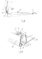
- the vehicle shown in Figure 1 has a body comprising in particular in the vicinity of the front axle 4, a cover 1, a front wing 2 and a front bumper 3.
- the shield of which only the skin is represented here, hides in its part upper a bumper device which will not be described.
- the lower part of the shield is provided with a movable flap 5 which is best seen in Figures 2 to 5.
- the flap 5 is composed of a bottom wall 5 a and a front wall 5 b of rounded shape, the height of which decreases from its central part in the direction of its two lateral ends directed towards the rear, which end substantially at the level of the bottom wall 5 a .
- This configuration of the flap makes it a box open at the top.
- the skin of the shield 3 has an opening 6 which serves as an air intake and allows the introduction of an air flow 7 behind the skin of the shield, above the flap 5 when the vehicle is in motion.
- the interior of the shield downstream of the opening 6 constitutes a pressure 8 which is closed lower by the flap 5 shaped in a housing.
- the flap is articulated in the example described at its rear end 9 around a transverse axis 10 perpendicular to the direction of movement of the vehicle.
- the front wall 5b of the flap has an upper edge 11 directed towards the front.
- the skin of the shield 3 ends at its lower part by a flange 13 directed towards the interior.
- the articulation 10 of the flap is provided with a device 14 integrated into the shield forming both a shock absorber and a mechanism for returning the flap to the high position.
- the depression created under the vehicle by the speed also tends to make rotate the flap.
- the damper 14 is calibrated so as to delay the descent of the flap, as seen in Figure 6.
- the delay d is due to the presence of the shock absorber, which thus filters brief overruns of the threshold speed Vd so as to retain only lasting overruns, so that the flap does not oscillate between its two positions when the vehicle speed is close to this threshold Vd.
- the rise threshold speed Vm is lower than the speed descent threshold Vd, which stabilizes the mud flap when the vehicle speed remains close to the speed which caused a change of position of the flap.
- the shield has internally a counter blade 15 which has the function of returning to the chassis of the vehicle, by through the attachment of the shield, the forces undergone by the articulation 10 of the flap, so as not to deform the shield when the flap is in the low position.
- a bumper comprising a skin 16 and a flap 17 separated by an air inlet 18.
- the skin 16 is reinforced by an energy absorption powder 19, as this is well known.
- the skin 16 and the beam 19 constitute a high support for the bumper.
- the flap 17 is reinforced by a cross member 20, which is less rigid than the energy absorption beam 19.
- the flap 17 constitutes a low support for the bumper.
- This low support completes the bumper to distribute the forces undergone by a pedestrian's leg in the event of an impact against the front of the vehicle.
- the flap For its reinforcement, the flap has longitudinal ribs 21 and it is fixed to the engine cradle 22 of the engine by means of a hinge 23.
- the flap is articulated by means of one or more axes.
- the rear of the flap a flexible part capable of deforming to allow a certain vertical travel of the front part of the mud flap when the vehicle is moving.
- FIG. 8 shows a flap 25 which comprises a flexible rear part 26 having a shape allowing a certain movement of the front part 27 of the flap.
- This flap 25 is shown in this figure in broken lines after pivoting down.
- the angular movement is approximately 7 °.
- the leading edge of the flap advantageously consists of a piece reported, as shown in Figure 9.
- This figure partially shows the front part of a flap comprising a bottom wall 32 and an upright 35 provided with openings 34.
- the upright 35 also includes vertical stiffening ribs 36.
- a part 31 intended to constitute the leading edge of the flap is attached on the amount 35.
- This part 31 has, at the rear, tabs 33 intended to snap in the aforementioned openings 34.
- the rear shield 44 has a rounded shape at the bottom, extending forward through a bottom wall 45 which is almost horizontal.
- the flap consists of a piece 46 which extends over almost the entire width of the vehicle and comprises a substantially planar upper face 47.
- the flap 46 is pivotally mounted around an axis 48, which allows it to take a high position called low speed position, shown in broken lines in Figure 10 and a low position called high speed position, shown in lines full.
- the upper face 47 of the flap is substantially parallel to the bottom wall 45 of the shield.
- the flap In the low position, the flap is inclined relative to the bottom wall 45 of the shield.
- the passage for the air flow from below the vehicle presents a decreasing cross section from the front to the rear of the vehicle.
- the bib and the wall 45 form a venturi which accelerates the air at the exit of the vehicle and reduces the drag of this last.
- the return of the flap to its high position is ensured by a return spring 50 whose stiffness is adjusted so that the change of position of the flap takes place at the desired vehicle travel speed.
- a stop mechanism (not shown) blocks the flap in the low position.
- a person skilled in the art will know how to arrange or arrange these stops so as to benefit from the care on the high ground of the vehicle when the flap is in the high position.
Landscapes
- Engineering & Computer Science (AREA)
- Chemical & Material Sciences (AREA)
- Combustion & Propulsion (AREA)
- Transportation (AREA)
- Mechanical Engineering (AREA)
- Body Structure For Vehicles (AREA)
Applications Claiming Priority (2)
| Application Number | Priority Date | Filing Date | Title |
|---|---|---|---|
| FR9907619A FR2795039B1 (fr) | 1999-06-16 | 1999-06-16 | Bouclier a bavette inferieure mobile |
| FR9907619 | 1999-06-16 |
Publications (2)
| Publication Number | Publication Date |
|---|---|
| EP1060976A1 true EP1060976A1 (de) | 2000-12-20 |
| EP1060976B1 EP1060976B1 (de) | 2003-12-10 |
Family
ID=9546870
Family Applications (1)
| Application Number | Title | Priority Date | Filing Date |
|---|---|---|---|
| EP00401719A Expired - Lifetime EP1060976B1 (de) | 1999-06-16 | 2000-06-16 | Stossfänger mit bewegbarem Untersatz |
Country Status (4)
| Country | Link |
|---|---|
| EP (1) | EP1060976B1 (de) |
| DE (1) | DE60007029T2 (de) |
| ES (1) | ES2209781T3 (de) |
| FR (1) | FR2795039B1 (de) |
Cited By (3)
| Publication number | Priority date | Publication date | Assignee | Title |
|---|---|---|---|---|
| FR2820390A1 (fr) * | 2001-02-07 | 2002-08-09 | Plastic Omnium Cie | Face avant technique de vehicule automobile avec poutre basse |
| WO2015124281A1 (en) * | 2014-02-20 | 2015-08-27 | Daimler Ag | Bumper assembly for a commercial vehicle |
| US20210300485A1 (en) * | 2020-03-27 | 2021-09-30 | Subaru Corporation | Airflow adjusting apparatus |
Families Citing this family (5)
| Publication number | Priority date | Publication date | Assignee | Title |
|---|---|---|---|---|
| DE102004032733B4 (de) * | 2004-07-07 | 2010-07-08 | Bayerische Motoren Werke Aktiengesellschaft | Heckspoilereinrichtung |
| FR2927303A1 (fr) | 2008-02-08 | 2009-08-14 | Peugeot Citroen Automobiles Sa | Dispositif pour reduire la trainee et/ou la portance d'un vehicule automobile et vehicule automobile equipe d'un tel dispositif |
| DE102009034906A1 (de) * | 2009-07-28 | 2011-02-03 | GM Global Technology Operations, Inc., Detroit | Vorderteil für eine Kraftfahrzeugkarosserie |
| FR2952343B1 (fr) | 2009-11-06 | 2011-12-09 | Peugeot Citroen Automobiles Sa | Systeme de deviation d'un flux d'air traversant pour un vehicule automobile. |
| CN104210557A (zh) * | 2014-08-30 | 2014-12-17 | 常州市万泰模具有限公司 | 分流式砂石挡 |
Citations (2)
| Publication number | Priority date | Publication date | Assignee | Title |
|---|---|---|---|---|
| FR2540813A1 (fr) | 1983-02-10 | 1984-08-17 | Equip Publicitaires Ste Nl | Perfectionnements aux deflecteurs du type " spoiler " pour vehicules automobiles |
| US4659130A (en) | 1982-12-10 | 1987-04-21 | Alfa Romeo Auto S.P.A. | Automatically positionable spoiler for a motor vehicle |
Family Cites Families (1)
| Publication number | Priority date | Publication date | Assignee | Title |
|---|---|---|---|---|
| DE3625814A1 (de) * | 1986-07-30 | 1988-02-18 | Bayerische Motoren Werke Ag | Kraftfahrzeug, insbesondere personenkraftwagen |
-
1999
- 1999-06-16 FR FR9907619A patent/FR2795039B1/fr not_active Expired - Fee Related
-
2000
- 2000-06-16 ES ES00401719T patent/ES2209781T3/es not_active Expired - Lifetime
- 2000-06-16 DE DE60007029T patent/DE60007029T2/de not_active Expired - Lifetime
- 2000-06-16 EP EP00401719A patent/EP1060976B1/de not_active Expired - Lifetime
Patent Citations (2)
| Publication number | Priority date | Publication date | Assignee | Title |
|---|---|---|---|---|
| US4659130A (en) | 1982-12-10 | 1987-04-21 | Alfa Romeo Auto S.P.A. | Automatically positionable spoiler for a motor vehicle |
| FR2540813A1 (fr) | 1983-02-10 | 1984-08-17 | Equip Publicitaires Ste Nl | Perfectionnements aux deflecteurs du type " spoiler " pour vehicules automobiles |
Cited By (5)
| Publication number | Priority date | Publication date | Assignee | Title |
|---|---|---|---|---|
| FR2820390A1 (fr) * | 2001-02-07 | 2002-08-09 | Plastic Omnium Cie | Face avant technique de vehicule automobile avec poutre basse |
| EP1231131A1 (de) * | 2001-02-07 | 2002-08-14 | Compagnie Plastic Omnium | Kraftfahrzeugfrontendmodul mit Verbindungselement zu einem unteren Querträger und Baugruppe aus Frontendmodul und seinem unteren Querträger |
| WO2015124281A1 (en) * | 2014-02-20 | 2015-08-27 | Daimler Ag | Bumper assembly for a commercial vehicle |
| US20210300485A1 (en) * | 2020-03-27 | 2021-09-30 | Subaru Corporation | Airflow adjusting apparatus |
| US11661122B2 (en) * | 2020-03-27 | 2023-05-30 | Subaru Corporation | Airflow adjusting apparatus |
Also Published As
| Publication number | Publication date |
|---|---|
| DE60007029D1 (de) | 2004-01-22 |
| EP1060976B1 (de) | 2003-12-10 |
| FR2795039B1 (fr) | 2001-08-10 |
| ES2209781T3 (es) | 2004-07-01 |
| FR2795039A1 (fr) | 2000-12-22 |
| DE60007029T2 (de) | 2004-09-16 |
Similar Documents
| Publication | Publication Date | Title |
|---|---|---|
| EP1405783B1 (de) | Stossfänger für ein Fahrzeug mit einem Spoiler, der zwischen drei stabilen Gleichgewichtspositionen verstellbar ist | |
| FR2962708A1 (fr) | Dispositif de guidage d'air pour un vehicule automobile | |
| WO2018109310A1 (fr) | Becquet pour véhicule automobile comprenant des écopes mobiles | |
| FR2780927A1 (fr) | Dispositif de fixation des crosses d'un pare-chocs sur une aile de carrosserie de vehicule | |
| WO2005087560A1 (fr) | Element de liaison de balai d’essuie-glace comportant un logement creux ouvert vers le haut | |
| EP2042388B1 (de) | Vorrichtung zum Schutz der Fußgänger und mit dieser Vorrichtung ausgerüstetes Fahrzeug | |
| EP1060976B1 (de) | Stossfänger mit bewegbarem Untersatz | |
| EP2882633B1 (de) | Deflektorvorrichtung und kraftfahrzeug mit vorderblende mit dieser deflektorvorrichtung | |
| FR2814962A1 (fr) | Perfectionnement pour dispositif de retenue d'une chaussure sur une planche de glisse sur neige du type surf | |
| WO2019063730A1 (fr) | Dispositif déflecteur de véhicule automobile | |
| FR3056502A1 (fr) | Retroviseur exterieur de vehicule automobile | |
| EP2651700B1 (de) | Vorderteil eines fahrzeuges, insbesondere eines kraftfahrzeuges, mit verbesserter sicherheit im falle eines fussgänger-aufpralls | |
| FR2913710A1 (fr) | Poignee eclairante pour vehicule automobile | |
| EP3060455B1 (de) | Kraftfahrzeugvorderstruktur mit einem unter dem stossfänger angeordneten beweglichen spoiler | |
| FR2963309A1 (fr) | Ecran aerodynamique fixe sous la partie arriere du soubassement d'un vehicule automobile et vehicule ainsi equipe. | |
| EP3812216B1 (de) | Einziehbare rückwärtsfahrkamera in einem beweglichen spoiler | |
| FR2943303A1 (fr) | Partie avant de vehicule automobile | |
| FR2540813A1 (fr) | Perfectionnements aux deflecteurs du type " spoiler " pour vehicules automobiles | |
| EP1043218B1 (de) | Aerodynamischer Windabweiser mit einstellbarer Neigung für Lastkraftwagen | |
| EP1893424B1 (de) | Boomerang-artiger trägerarm mit ansteigender erweiterung einer kante und entsprechendes fahrzeug | |
| FR2998221A1 (fr) | Vitre, notamment pare-brise de vehicule automobile | |
| FR3036714A1 (fr) | Dispositif de signalisation routiere horizontale deformable retractable | |
| EP0506542B1 (de) | Lamellenluftleitblech, insbesondere für Kraftfahrzeuge | |
| FR2706372A1 (fr) | Visière de protection, notamment pour véhicule automobile. | |
| WO2011018570A2 (fr) | Partie avant de vehicule automobile. |
Legal Events
| Date | Code | Title | Description |
|---|---|---|---|
| PUAI | Public reference made under article 153(3) epc to a published international application that has entered the european phase |
Free format text: ORIGINAL CODE: 0009012 |
|
| AK | Designated contracting states |
Kind code of ref document: A1 Designated state(s): DE ES FR GB IT |
|
| AX | Request for extension of the european patent |
Free format text: AL;LT;LV;MK;RO;SI |
|
| 17P | Request for examination filed |
Effective date: 20010301 |
|
| AKX | Designation fees paid |
Free format text: DE ES FR GB IT |
|
| RAP1 | Party data changed (applicant data changed or rights of an application transferred) |
Owner name: RENAULT S.A.S. Owner name: COMPAGNIE PLASTIC OMNIUM |
|
| 17Q | First examination report despatched |
Effective date: 20021030 |
|
| GRAH | Despatch of communication of intention to grant a patent |
Free format text: ORIGINAL CODE: EPIDOS IGRA |
|
| RTI1 | Title (correction) |
Free format text: MUD GUARD WITH MOVABLE LOWER SPOILER |
|
| GRAS | Grant fee paid |
Free format text: ORIGINAL CODE: EPIDOSNIGR3 |
|
| GRAA | (expected) grant |
Free format text: ORIGINAL CODE: 0009210 |
|
| RTI1 | Title (correction) |
Free format text: APRON WITH MOVABLE LOWER SPOILER |
|
| AK | Designated contracting states |
Kind code of ref document: B1 Designated state(s): DE ES FR GB IT |
|
| REG | Reference to a national code |
Ref country code: GB Ref legal event code: FG4D Free format text: NOT ENGLISH |
|
| REF | Corresponds to: |
Ref document number: 60007029 Country of ref document: DE Date of ref document: 20040122 Kind code of ref document: P |
|
| GBT | Gb: translation of ep patent filed (gb section 77(6)(a)/1977) |
Effective date: 20040310 |
|
| REG | Reference to a national code |
Ref country code: ES Ref legal event code: FG2A Ref document number: 2209781 Country of ref document: ES Kind code of ref document: T3 |
|
| PLBE | No opposition filed within time limit |
Free format text: ORIGINAL CODE: 0009261 |
|
| STAA | Information on the status of an ep patent application or granted ep patent |
Free format text: STATUS: NO OPPOSITION FILED WITHIN TIME LIMIT |
|
| 26N | No opposition filed |
Effective date: 20040913 |
|
| REG | Reference to a national code |
Ref country code: FR Ref legal event code: PLFP Year of fee payment: 17 |
|
| PGFP | Annual fee paid to national office [announced via postgrant information from national office to epo] |
Ref country code: GB Payment date: 20160621 Year of fee payment: 17 Ref country code: ES Payment date: 20160614 Year of fee payment: 17 Ref country code: DE Payment date: 20160621 Year of fee payment: 17 |
|
| PGFP | Annual fee paid to national office [announced via postgrant information from national office to epo] |
Ref country code: IT Payment date: 20160628 Year of fee payment: 17 |
|
| REG | Reference to a national code |
Ref country code: FR Ref legal event code: PLFP Year of fee payment: 18 |
|
| REG | Reference to a national code |
Ref country code: DE Ref legal event code: R119 Ref document number: 60007029 Country of ref document: DE |
|
| GBPC | Gb: european patent ceased through non-payment of renewal fee |
Effective date: 20170616 |
|
| PG25 | Lapsed in a contracting state [announced via postgrant information from national office to epo] |
Ref country code: GB Free format text: LAPSE BECAUSE OF NON-PAYMENT OF DUE FEES Effective date: 20170616 Ref country code: DE Free format text: LAPSE BECAUSE OF NON-PAYMENT OF DUE FEES Effective date: 20180103 |
|
| PG25 | Lapsed in a contracting state [announced via postgrant information from national office to epo] |
Ref country code: IT Free format text: LAPSE BECAUSE OF NON-PAYMENT OF DUE FEES Effective date: 20170616 |
|
| REG | Reference to a national code |
Ref country code: FR Ref legal event code: PLFP Year of fee payment: 19 |
|
| PGFP | Annual fee paid to national office [announced via postgrant information from national office to epo] |
Ref country code: FR Payment date: 20180628 Year of fee payment: 19 |
|
| REG | Reference to a national code |
Ref country code: ES Ref legal event code: FD2A Effective date: 20181108 |
|
| PG25 | Lapsed in a contracting state [announced via postgrant information from national office to epo] |
Ref country code: ES Free format text: LAPSE BECAUSE OF NON-PAYMENT OF DUE FEES Effective date: 20170617 |
|
| PG25 | Lapsed in a contracting state [announced via postgrant information from national office to epo] |
Ref country code: FR Free format text: LAPSE BECAUSE OF NON-PAYMENT OF DUE FEES Effective date: 20190630 |