EP1231131A1 - Kraftfahrzeugfrontendmodul mit Verbindungselement zu einem unteren Querträger und Baugruppe aus Frontendmodul und seinem unteren Querträger - Google Patents
Kraftfahrzeugfrontendmodul mit Verbindungselement zu einem unteren Querträger und Baugruppe aus Frontendmodul und seinem unteren Querträger Download PDFInfo
- Publication number
- EP1231131A1 EP1231131A1 EP02290305A EP02290305A EP1231131A1 EP 1231131 A1 EP1231131 A1 EP 1231131A1 EP 02290305 A EP02290305 A EP 02290305A EP 02290305 A EP02290305 A EP 02290305A EP 1231131 A1 EP1231131 A1 EP 1231131A1
- Authority
- EP
- European Patent Office
- Prior art keywords
- technical front
- low beam
- front panel
- rigid
- vehicle
- Prior art date
- Legal status (The legal status is an assumption and is not a legal conclusion. Google has not performed a legal analysis and makes no representation as to the accuracy of the status listed.)
- Granted
Links
Images



Classifications
-
- B—PERFORMING OPERATIONS; TRANSPORTING
- B62—LAND VEHICLES FOR TRAVELLING OTHERWISE THAN ON RAILS
- B62D—MOTOR VEHICLES; TRAILERS
- B62D35/00—Vehicle bodies characterised by streamlining
- B62D35/005—Front spoilers
-
- B—PERFORMING OPERATIONS; TRANSPORTING
- B62—LAND VEHICLES FOR TRAVELLING OTHERWISE THAN ON RAILS
- B62D—MOTOR VEHICLES; TRAILERS
- B62D25/00—Superstructure or monocoque structure sub-units; Parts or details thereof not otherwise provided for
- B62D25/08—Front or rear portions
- B62D25/082—Engine compartments
- B62D25/084—Radiator supports
-
- B—PERFORMING OPERATIONS; TRANSPORTING
- B62—LAND VEHICLES FOR TRAVELLING OTHERWISE THAN ON RAILS
- B62D—MOTOR VEHICLES; TRAILERS
- B62D35/00—Vehicle bodies characterised by streamlining
- B62D35/02—Streamlining the undersurfaces
-
- Y—GENERAL TAGGING OF NEW TECHNOLOGICAL DEVELOPMENTS; GENERAL TAGGING OF CROSS-SECTIONAL TECHNOLOGIES SPANNING OVER SEVERAL SECTIONS OF THE IPC; TECHNICAL SUBJECTS COVERED BY FORMER USPC CROSS-REFERENCE ART COLLECTIONS [XRACs] AND DIGESTS
- Y02—TECHNOLOGIES OR APPLICATIONS FOR MITIGATION OR ADAPTATION AGAINST CLIMATE CHANGE
- Y02T—CLIMATE CHANGE MITIGATION TECHNOLOGIES RELATED TO TRANSPORTATION
- Y02T10/00—Road transport of goods or passengers
- Y02T10/80—Technologies aiming to reduce greenhouse gasses emissions common to all road transportation technologies
- Y02T10/88—Optimized components or subsystems, e.g. lighting, actively controlled glasses
Definitions
- the present invention relates to a technical front panel of a motor vehicle provided with a means of connection to a low beam and an assembly consisting of a face before technique and its low beam.
- the low beam is preferably connected to structural elements of the vehicle. Its attachment to said structural elements can intervene either during shoeing, or shortly before mounting the bumper.
- the beam is directly secured to the vehicle structure and its positioning relative to the body is insufficiently precise to respect the usual assembly tolerances of visible bodywork elements.
- the beam thus fixed cannot be used as a reference for the positioning of a visible part, in particular in the vertical direction.
- a possibility of fixing the low beam consists of integrating it into the assembled bumper. If the bumper is correctly positioned in relation to other body parts, which is generally the case, we can then consider that the low beam is properly positioned, in Z and / or in Y.
- the weight of the low beam means strengthening the bumper and this results in additional cost as well as an unwanted increase in vehicle weight.
- the present invention aims to provide a solution for mounting the low beam on the vehicle, ensuring precise positioning of said low beam relative to the visible parts of the bodywork, in particular in the vertical direction.
- the subject of the present invention is a technical front face of a motor vehicle, which is characterized in that it comprises a rigid connecting means in Z, that is to say in the vertical direction, extending downward and intended to be secured to a beam low.
- the invention seeks to take advantage of the fact that the technical front face is correctly referenced in Z relative to the vehicle body, since it constitutes one of the supports. Consequently, thanks to the rigid Z connection means, the low beam is is also correctly referenced in Z.
- Another possibility resulting from the correct positioning of the low beam is use the latter as a support for components such as fog lights, providing on it arrangements for receiving these components.
- the technical front face has two vertical legs bordering a central part for receiving a cooling module. These legs can constitute, by a downward extension of each of them, the rigid connection means in Z of the technical front face according to the invention.
- the rigid connection means in Z serves as a single support for the beam low.
- the shocks undergone by the low beam are therefore taken up by this connecting means and it it is unnecessary to provide supports behind the low beam to ensure recovery efforts in the event of impacts, such as side members coming for example from the cradle engine.
- a first embodiment of the invention consists in interposing, between the low beam and the rigid connection means, a fusible zone which self-destructs as soon as the force to be transmitted becomes large enough to damage the technical front panel or its means of attachment to the vehicle.
- the rigid Z-shaped means connecting the low beam on the technical front panel is secured to the low beam by means of fixing fuses which have the same role as previously described, namely to avoid a recovery by the technical front of the efforts too high, in order to preserve the latter and its means of attachment to the vehicle.
- An additional advantage resulting from the integration of the low beam in the technical front end is that new functions, traditionally external to a technical front face, can be incorporated into the technical front face according to the invention.
- the air flow under the vehicle can be improved thanks to a low wall rigid vertical arranged transversely to the vehicle projecting from the underside of the low beam.
- a low wall advantageously replaces a fixed spoiler.
- the position of the wall in the longitudinal direction of the vehicle makes it possible to avoid sidewalk or parking ramp.
- a fixed spoiler With a fixed spoiler, the risk of deterioration by contact with a sidewalk or a parking ramp can only be resolved by using flexible materials, which makes such a fixed spoiler much more expensive than the low wall rigid vertical of the invention.
- the invention also relates to an assembly consisting of a front face technique as described above and by the low beam subject to its means of rigid Z connection.
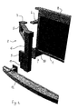
- the technical front face shown in FIGS. 1 and 2 is of the type consisting of three parts, namely a central part formed by a cooling module 1 and two side parts 2 which are fixed to the chassis of the vehicle and to which the 1 central cooling is connected to form the technical front panel in his outfit.
- each side part 2 includes a fixing lug upper 3 directed towards the rear and intended to be fixed to a lining support wing 4.
- each side part 2 is constituted by a frame 5, which is arranged to accommodate an optical unit (not shown), and a vertical leg 6 which borders a central space 7 of the technical front face, intended to accommodate the module cooling 1, visible in Figure 2.
- the vertical leg 6 can take different forms, in particular non- cylindrical with non-constant cross-section.
- Each vertical leg 6 extends from the upper edge of the front face technique, which here is an upper cross member 8 belonging to the module cooling down to the side members of the vehicle, i.e. lower than the location of a shock beam (not shown).
- the location of the impact beam is materialized by a fixing plate 9 integral with the leg 6, comprising a front face receiving said shock beam and a rear face to which the corresponding spar 10 of the vehicle chassis comes to stare.
- the fixing plate 9 is sandwiched between the beam impact and the side member 10.
- the technical front end is fixed to the vehicle by its upper fixing lugs 3, which are subject to the lining supports of wings 4, and by the fixing plates 9 of the impact beam, secured to the stringers 10.
- each vertical leg 6 located below the fixing plate 9 supports a second fixing plate 11, hereinafter designated lower plate, for a low beam 12 located under the impact beam and serving in particular, as is known, to deal with pedestrian impacts.
- Figure 3 differs from the previous only by the composition of the technical front panel, which no longer consists of three parts, but is presents in one piece, before its central part 1 'containing the elements of component of the cooling module described above, is its two side parts 2 'bordering the central part 1'.
- FIGS. 1 and 2 which are identical in FIG. 3 bear the same reference numbers.
- the base plate 11 is thus reinforced in order to be able to withstand the stresses arising from shocks.
- a fuse zone 13 is provided between the low beam 12 and its mounting plate 11.
- no fuse zone is provided but the beam base is connected to the technical front panel by a fuse fixing means.
Landscapes
- Engineering & Computer Science (AREA)
- Chemical & Material Sciences (AREA)
- Combustion & Propulsion (AREA)
- Transportation (AREA)
- Mechanical Engineering (AREA)
- Body Structure For Vehicles (AREA)
Applications Claiming Priority (2)
| Application Number | Priority Date | Filing Date | Title |
|---|---|---|---|
| FR0101650 | 2001-02-07 | ||
| FR0101650A FR2820390B1 (fr) | 2001-02-07 | 2001-02-07 | Face avant technique de vehicule automobile avec poutre basse |
Publications (2)
| Publication Number | Publication Date |
|---|---|
| EP1231131A1 true EP1231131A1 (de) | 2002-08-14 |
| EP1231131B1 EP1231131B1 (de) | 2009-01-14 |
Family
ID=8859725
Family Applications (1)
| Application Number | Title | Priority Date | Filing Date |
|---|---|---|---|
| EP02290305A Expired - Lifetime EP1231131B1 (de) | 2001-02-07 | 2002-02-07 | Kraftfahrzeugfrontendmodul mit Verbindungselement zu einem unteren Querträger und Baugruppe aus Frontendmodul und seinem unteren Querträger |
Country Status (4)
| Country | Link |
|---|---|
| EP (1) | EP1231131B1 (de) |
| DE (1) | DE60230828D1 (de) |
| ES (1) | ES2321063T3 (de) |
| FR (1) | FR2820390B1 (de) |
Cited By (1)
| Publication number | Priority date | Publication date | Assignee | Title |
|---|---|---|---|---|
| DE102004007571B4 (de) * | 2003-12-24 | 2017-12-21 | Volkswagen Ag | Vorderwagen für ein Fahrzeug, insbesondere für ein Kraftfahrzeug |
Families Citing this family (2)
| Publication number | Priority date | Publication date | Assignee | Title |
|---|---|---|---|---|
| FR2875472B1 (fr) * | 2004-09-20 | 2008-04-04 | Faurecia Bloc Avant | Face avant pour vehicule automobile et procede de montage correspondant |
| ATE510750T1 (de) * | 2007-09-21 | 2011-06-15 | Peguform Gmbh | Kraftfahrzeug-frontendmodul |
Citations (7)
| Publication number | Priority date | Publication date | Assignee | Title |
|---|---|---|---|---|
| DE4229945A1 (de) * | 1992-09-08 | 1994-03-10 | Audi Ag | Kraftfahrzeug |
| EP0908374A1 (de) * | 1997-10-09 | 1999-04-14 | Automobiles Peugeot | Vorrichtung zur Befestigung einer Forderfront an einem Vorderbau eines Kraftfahrzeuges |
| WO1999021748A1 (en) * | 1997-10-24 | 1999-05-06 | Decoma International Inc. | End module assembly for installation on a vehicle and method for making the same |
| FR2791628A1 (fr) * | 1999-03-29 | 2000-10-06 | Peguform France | Combinaison d'une peau de pare-chocs et d'un carenage sous moteur pour vehicule |
| EP1060976A1 (de) * | 1999-06-16 | 2000-12-20 | Compagnie Plastic Omnium | Stossfänger mit bewegbarem Untersatz |
| WO2001000478A1 (de) * | 1999-06-23 | 2001-01-04 | Dynamit Nobel Kunststoff Gmbh | Frontendmodul für ein kraftfahrzeug |
| DE10105562A1 (de) * | 2000-02-07 | 2001-08-09 | Faurecia Bloc Avant Nanterre | Vorderfront für Kraftfahrzeuge |
-
2001
- 2001-02-07 FR FR0101650A patent/FR2820390B1/fr not_active Expired - Fee Related
-
2002
- 2002-02-07 EP EP02290305A patent/EP1231131B1/de not_active Expired - Lifetime
- 2002-02-07 ES ES02290305T patent/ES2321063T3/es not_active Expired - Lifetime
- 2002-02-07 DE DE60230828T patent/DE60230828D1/de not_active Expired - Lifetime
Patent Citations (7)
| Publication number | Priority date | Publication date | Assignee | Title |
|---|---|---|---|---|
| DE4229945A1 (de) * | 1992-09-08 | 1994-03-10 | Audi Ag | Kraftfahrzeug |
| EP0908374A1 (de) * | 1997-10-09 | 1999-04-14 | Automobiles Peugeot | Vorrichtung zur Befestigung einer Forderfront an einem Vorderbau eines Kraftfahrzeuges |
| WO1999021748A1 (en) * | 1997-10-24 | 1999-05-06 | Decoma International Inc. | End module assembly for installation on a vehicle and method for making the same |
| FR2791628A1 (fr) * | 1999-03-29 | 2000-10-06 | Peguform France | Combinaison d'une peau de pare-chocs et d'un carenage sous moteur pour vehicule |
| EP1060976A1 (de) * | 1999-06-16 | 2000-12-20 | Compagnie Plastic Omnium | Stossfänger mit bewegbarem Untersatz |
| WO2001000478A1 (de) * | 1999-06-23 | 2001-01-04 | Dynamit Nobel Kunststoff Gmbh | Frontendmodul für ein kraftfahrzeug |
| DE10105562A1 (de) * | 2000-02-07 | 2001-08-09 | Faurecia Bloc Avant Nanterre | Vorderfront für Kraftfahrzeuge |
Cited By (1)
| Publication number | Priority date | Publication date | Assignee | Title |
|---|---|---|---|---|
| DE102004007571B4 (de) * | 2003-12-24 | 2017-12-21 | Volkswagen Ag | Vorderwagen für ein Fahrzeug, insbesondere für ein Kraftfahrzeug |
Also Published As
| Publication number | Publication date |
|---|---|
| DE60230828D1 (de) | 2009-03-05 |
| FR2820390A1 (fr) | 2002-08-09 |
| EP1231131B1 (de) | 2009-01-14 |
| FR2820390B1 (fr) | 2003-08-08 |
| ES2321063T3 (es) | 2009-06-02 |
Similar Documents
| Publication | Publication Date | Title |
|---|---|---|
| EP1067005B1 (de) | Anordnung zum Befestigen von Modulen auf einem Träger in einem Kraftfahrzeug | |
| FR2783796A1 (fr) | Facade avant composite metal/plastique renforcee surmoulee pour vehicule automobile | |
| EP1907264B1 (de) | Ein vorderes kraftfahrzeugfahrgestell stützende struktur mit verbindungsmitteln in form eines hohlkörpers eines mini-trägers mit seitengliedern und entsprechendes fahrzeug | |
| EP2744698B1 (de) | Kraftfahrzeugkarosserie mit einer versteifungsvorrichtung | |
| EP1419936A1 (de) | Unterer Stossbalken für den Zusammenstoss eines Fussgängers mit einem Kraftfahrzeug und Kraftfahrzeugstossstange mit einem solchen Stossbalken | |
| EP1231131B1 (de) | Kraftfahrzeugfrontendmodul mit Verbindungselement zu einem unteren Querträger und Baugruppe aus Frontendmodul und seinem unteren Querträger | |
| EP1916152B2 (de) | Vorderstruktur eines Kraftfahrzeugs und damit ausgestattetes Kraftfahrzeug | |
| EP1101691A1 (de) | Vorder- Viertel- Befestigung auf Querträger | |
| FR2816273A1 (fr) | Face avant de vehicule automobile comprenant une poutre pare-chocs | |
| EP1603787B1 (de) | Frontmodul eines fahrzeugs | |
| EP1693283B1 (de) | Vorderbau für ein Kraftfahrzeug | |
| FR2816272A1 (fr) | Face avant avec bouclier pour vehicule automobile | |
| EP4139143B1 (de) | Elektrisches oder hybridfahrzeug mit einer rechten verstärkung und einer linken verstärkung | |
| EP0348253B1 (de) | Frontaufbau eines Kraftfahrzeugs mit quereigebautem Motor | |
| EP1693284B1 (de) | Stirnwandanordnung für Kraftfahrzeug | |
| WO2006000722A1 (fr) | Bloc projecteur pour vehicule automobile | |
| EP2132055A2 (de) | Verfahren zur montage eines transversalen unterstrukturelements und einer technischen fronttafel | |
| EP1510445B1 (de) | Aufbaustruktur für ein Kraftfahrzeug | |
| FR2887217A1 (fr) | Structure de support d'un pavillon de vehicule automobile | |
| EP3974294B1 (de) | Verfahren zum zusammenbau eines elektro- oder hybridfahrzeugs | |
| EP2822840B1 (de) | Kraftfahrzeugkarosserie mit einem kabelverstärkten verkleidungsbereich | |
| EP2331388B1 (de) | Anordnung für die montage des frontendmoduls eines fahrzeugs | |
| FR3145140A1 (fr) | Longeronnet avant pour véhicule automobile comportant un renfort mécanique | |
| FR2789640A1 (fr) | Dispositif de fixation rapide pour feux arriere de vehicules routiers ou agricoles | |
| FR3162183A1 (fr) | Ensemble de parechocs pour une structure de châssis d’un véhicule automobile |
Legal Events
| Date | Code | Title | Description |
|---|---|---|---|
| PUAI | Public reference made under article 153(3) epc to a published international application that has entered the european phase |
Free format text: ORIGINAL CODE: 0009012 |
|
| AK | Designated contracting states |
Kind code of ref document: A1 Designated state(s): AT BE CH CY DE DK ES FI FR GB GR IE IT LI LU MC NL PT SE TR |
|
| AX | Request for extension of the european patent |
Free format text: AL;LT;LV;MK;RO;SI |
|
| RIN1 | Information on inventor provided before grant (corrected) |
Inventor name: DECKER, LAURENT Inventor name: BARBIER, PASCAL Inventor name: ROCHON, CYRILLE Inventor name: CHERON, HUGUES Inventor name: MALTESTE, STEPHANE |
|
| 17P | Request for examination filed |
Effective date: 20030211 |
|
| AKX | Designation fees paid |
Designated state(s): DE ES FR GB IT |
|
| 17Q | First examination report despatched |
Effective date: 20031124 |
|
| APBN | Date of receipt of notice of appeal recorded |
Free format text: ORIGINAL CODE: EPIDOSNNOA2E |
|
| APBR | Date of receipt of statement of grounds of appeal recorded |
Free format text: ORIGINAL CODE: EPIDOSNNOA3E |
|
| APBV | Interlocutory revision of appeal recorded |
Free format text: ORIGINAL CODE: EPIDOSNIRAPE |
|
| APBD | Information on interlocutory revision deleted |
Free format text: ORIGINAL CODE: EPIDOSDIRAPE |
|
| APBN | Date of receipt of notice of appeal recorded |
Free format text: ORIGINAL CODE: EPIDOSNNOA2E |
|
| APBR | Date of receipt of statement of grounds of appeal recorded |
Free format text: ORIGINAL CODE: EPIDOSNNOA3E |
|
| APBV | Interlocutory revision of appeal recorded |
Free format text: ORIGINAL CODE: EPIDOSNIRAPE |
|
| APBD | Information on interlocutory revision deleted |
Free format text: ORIGINAL CODE: EPIDOSDIRAPE |
|
| APBK | Appeal reference recorded |
Free format text: ORIGINAL CODE: EPIDOSNREFNE |
|
| APAV | Appeal reference deleted |
Free format text: ORIGINAL CODE: EPIDOSDREFNE |
|
| APBK | Appeal reference recorded |
Free format text: ORIGINAL CODE: EPIDOSNREFNE |
|
| APAF | Appeal reference modified |
Free format text: ORIGINAL CODE: EPIDOSCREFNE |
|
| APBT | Appeal procedure closed |
Free format text: ORIGINAL CODE: EPIDOSNNOA9E |
|
| GRAP | Despatch of communication of intention to grant a patent |
Free format text: ORIGINAL CODE: EPIDOSNIGR1 |
|
| GRAC | Information related to communication of intention to grant a patent modified |
Free format text: ORIGINAL CODE: EPIDOSCIGR1 |
|
| GRAS | Grant fee paid |
Free format text: ORIGINAL CODE: EPIDOSNIGR3 |
|
| GRAA | (expected) grant |
Free format text: ORIGINAL CODE: 0009210 |
|
| AK | Designated contracting states |
Kind code of ref document: B1 Designated state(s): DE ES FR GB IT |
|
| REG | Reference to a national code |
Ref country code: GB Ref legal event code: FG4D Free format text: NOT ENGLISH |
|
| REF | Corresponds to: |
Ref document number: 60230828 Country of ref document: DE Date of ref document: 20090305 Kind code of ref document: P |
|
| REG | Reference to a national code |
Ref country code: ES Ref legal event code: FG2A Ref document number: 2321063 Country of ref document: ES Kind code of ref document: T3 |
|
| PLBE | No opposition filed within time limit |
Free format text: ORIGINAL CODE: 0009261 |
|
| STAA | Information on the status of an ep patent application or granted ep patent |
Free format text: STATUS: NO OPPOSITION FILED WITHIN TIME LIMIT |
|
| 26N | No opposition filed |
Effective date: 20091015 |
|
| PGFP | Annual fee paid to national office [announced via postgrant information from national office to epo] |
Ref country code: IT Payment date: 20110228 Year of fee payment: 10 |
|
| PG25 | Lapsed in a contracting state [announced via postgrant information from national office to epo] |
Ref country code: IT Free format text: LAPSE BECAUSE OF NON-PAYMENT OF DUE FEES Effective date: 20120207 |
|
| PGFP | Annual fee paid to national office [announced via postgrant information from national office to epo] |
Ref country code: ES Payment date: 20150326 Year of fee payment: 14 |
|
| REG | Reference to a national code |
Ref country code: FR Ref legal event code: PLFP Year of fee payment: 15 |
|
| REG | Reference to a national code |
Ref country code: FR Ref legal event code: PLFP Year of fee payment: 16 |
|
| REG | Reference to a national code |
Ref country code: FR Ref legal event code: PLFP Year of fee payment: 17 |
|
| PG25 | Lapsed in a contracting state [announced via postgrant information from national office to epo] |
Ref country code: ES Free format text: LAPSE BECAUSE OF NON-PAYMENT OF DUE FEES Effective date: 20160208 |
|
| REG | Reference to a national code |
Ref country code: ES Ref legal event code: FD2A Effective date: 20181205 |
|
| PGFP | Annual fee paid to national office [announced via postgrant information from national office to epo] |
Ref country code: GB Payment date: 20190218 Year of fee payment: 18 Ref country code: DE Payment date: 20190219 Year of fee payment: 18 |
|
| PGFP | Annual fee paid to national office [announced via postgrant information from national office to epo] |
Ref country code: FR Payment date: 20190225 Year of fee payment: 18 |
|
| REG | Reference to a national code |
Ref country code: DE Ref legal event code: R119 Ref document number: 60230828 Country of ref document: DE |
|
| GBPC | Gb: european patent ceased through non-payment of renewal fee |
Effective date: 20200207 |
|
| PG25 | Lapsed in a contracting state [announced via postgrant information from national office to epo] |
Ref country code: DE Free format text: LAPSE BECAUSE OF NON-PAYMENT OF DUE FEES Effective date: 20200901 Ref country code: FR Free format text: LAPSE BECAUSE OF NON-PAYMENT OF DUE FEES Effective date: 20200229 Ref country code: GB Free format text: LAPSE BECAUSE OF NON-PAYMENT OF DUE FEES Effective date: 20200207 |