EP1061748A2 - Videoobjektsegmentierung unter Verwendung von Aktivkonturmodellisierung mit globaler Relaxation - Google Patents
Videoobjektsegmentierung unter Verwendung von Aktivkonturmodellisierung mit globaler Relaxation Download PDFInfo
- Publication number
- EP1061748A2 EP1061748A2 EP00201976A EP00201976A EP1061748A2 EP 1061748 A2 EP1061748 A2 EP 1061748A2 EP 00201976 A EP00201976 A EP 00201976A EP 00201976 A EP00201976 A EP 00201976A EP 1061748 A2 EP1061748 A2 EP 1061748A2
- Authority
- EP
- European Patent Office
- Prior art keywords
- data points
- contour
- data
- image
- points
- Prior art date
- Legal status (The legal status is an assumption and is not a legal conclusion. Google has not performed a legal analysis and makes no representation as to the accuracy of the status listed.)
- Withdrawn
Links
Images



Classifications
-
- G—PHYSICS
- G06—COMPUTING OR CALCULATING; COUNTING
- G06T—IMAGE DATA PROCESSING OR GENERATION, IN GENERAL
- G06T9/00—Image coding
- G06T9/001—Model-based coding, e.g. wire frame
-
- G—PHYSICS
- G06—COMPUTING OR CALCULATING; COUNTING
- G06T—IMAGE DATA PROCESSING OR GENERATION, IN GENERAL
- G06T7/00—Image analysis
- G06T7/20—Analysis of motion
- G06T7/254—Analysis of motion involving subtraction of images
-
- G—PHYSICS
- G06—COMPUTING OR CALCULATING; COUNTING
- G06T—IMAGE DATA PROCESSING OR GENERATION, IN GENERAL
- G06T9/00—Image coding
- G06T9/20—Contour coding, e.g. using detection of edges
-
- G—PHYSICS
- G06—COMPUTING OR CALCULATING; COUNTING
- G06V—IMAGE OR VIDEO RECOGNITION OR UNDERSTANDING
- G06V10/00—Arrangements for image or video recognition or understanding
- G06V10/20—Image preprocessing
- G06V10/24—Aligning, centring, orientation detection or correction of the image
-
- G—PHYSICS
- G06—COMPUTING OR CALCULATING; COUNTING
- G06V—IMAGE OR VIDEO RECOGNITION OR UNDERSTANDING
- G06V10/00—Arrangements for image or video recognition or understanding
- G06V10/20—Image preprocessing
- G06V10/26—Segmentation of patterns in the image field; Cutting or merging of image elements to establish the pattern region, e.g. clustering-based techniques; Detection of occlusion
- G06V10/267—Segmentation of patterns in the image field; Cutting or merging of image elements to establish the pattern region, e.g. clustering-based techniques; Detection of occlusion by performing operations on regions, e.g. growing, shrinking or watersheds
-
- G—PHYSICS
- G06—COMPUTING OR CALCULATING; COUNTING
- G06V—IMAGE OR VIDEO RECOGNITION OR UNDERSTANDING
- G06V10/00—Arrangements for image or video recognition or understanding
- G06V10/20—Image preprocessing
- G06V10/28—Quantising the image, e.g. histogram thresholding for discrimination between background and foreground patterns
-
- G—PHYSICS
- G06—COMPUTING OR CALCULATING; COUNTING
- G06V—IMAGE OR VIDEO RECOGNITION OR UNDERSTANDING
- G06V10/00—Arrangements for image or video recognition or understanding
- G06V10/20—Image preprocessing
- G06V10/34—Smoothing or thinning of the pattern; Morphological operations; Skeletonisation
-
- G—PHYSICS
- G06—COMPUTING OR CALCULATING; COUNTING
- G06V—IMAGE OR VIDEO RECOGNITION OR UNDERSTANDING
- G06V10/00—Arrangements for image or video recognition or understanding
- G06V10/40—Extraction of image or video features
- G06V10/56—Extraction of image or video features relating to colour
-
- G—PHYSICS
- G06—COMPUTING OR CALCULATING; COUNTING
- G06V—IMAGE OR VIDEO RECOGNITION OR UNDERSTANDING
- G06V10/00—Arrangements for image or video recognition or understanding
- G06V10/70—Arrangements for image or video recognition or understanding using pattern recognition or machine learning
- G06V10/74—Image or video pattern matching; Proximity measures in feature spaces
- G06V10/75—Organisation of the matching processes, e.g. simultaneous or sequential comparisons of image or video features; Coarse-fine approaches, e.g. multi-scale approaches; using context analysis; Selection of dictionaries
- G06V10/755—Deformable models or variational models, e.g. snakes or active contours
-
- G—PHYSICS
- G06—COMPUTING OR CALCULATING; COUNTING
- G06V—IMAGE OR VIDEO RECOGNITION OR UNDERSTANDING
- G06V10/00—Arrangements for image or video recognition or understanding
- G06V10/40—Extraction of image or video features
- G06V10/62—Extraction of image or video features relating to a temporal dimension, e.g. time-based feature extraction; Pattern tracking
Definitions
- This invention relates to object segmentation and tracking within a sequence of image frames, and more particularly to object segmentation using an active contour model having global relaxation to maintain an optimal contour edge of an image object being tracked.
- active contour models also known as snakes
- snakes have been used for adjusting image features, in particular image object boundaries.
- active contour models involve overlaying an elastic curve onto an image.
- the curve i.e., snake
- An energy minimizing function is used which adapts the curve to image features such as lines and edges.
- the function is guided by external constraint forces and image forces. The best fit is achieved by minimizing a total energy computation of the curve.
- the energy computation is derived from (i) energy terms for internal tension (stretching) and stiffness (bending), and (ii) potential terms derived from image features (edges; corners).
- a pressure force also has been used to allow closed contours to inflate.
- the adjustment of the snake to the object feature is strongly influenced by the weighting parameters ⁇ , ⁇ , ⁇ , and ⁇ .
- Difficulties in applying conventional active contour models include: (i) being attracted to spurious local features (i.e., spurious edge points); and (ii) not being able to easily choose a reliable set of weighting parameters. Conventionally, iterations are applied to get the entire contour to converge to an optimal path.
- a new approach to contour modelling is an aspect of this invention. Such approach is described below in the summary of invention.
- Adaptive resonance theory is a system for self-organizing stable pattern recognition codes in real-time data in response to arbitrary sequences of input patterns. (See “Adaptive Pattern Classification and Universal Recoding: II ...,” by Stephen Grossberg, Biological Cybernetics 23, pp. 187-202 (1976)). It is based on the problem of discovering, learning and recognizing invariant properties of a data set, and is somewhat analogous to the human processes of perception and cognition. The invariant properties, called recognition codes, emerge in human perception through an individual's interaction with the environment. When these recognition codes emerge spontaneously, as in human perception, the process is said to be self-organizing.
- Adaptive Resonance Theory - 1 ('ART 1') networks implement a set of differential equations responsive to arbitrary sequences of binary input patterns.
- Adaptive Resonance Theory - 2 ('ART 2') networks self-organize stable recognition categories in response to arbitrary sequences of not only binary, but also analog (gray-scale, continuous-valued) input patterns. See “ART 2: Self-Organization of Stable Category Recognition Codes for Analog Input Patterns," by Gail A. Carpenter and Stephen Grossberg.
- a modified ART-2 network is implemented to achieve an inventive clustering and pattern recognition system for image object tracking.
- a system for image object tracking and segmentation includes (i) a modified adaptive resonance theory - 2 (M-ART2) model for detecting changes of scenes, (ii) a two-dimensional correlative autopredictive search (2D CAPS) method for object tracking, and (iii) an active contour model with global relaxation for defining optimal image object boundaries.
- M-ART2 modified adaptive resonance theory - 2
- 2D CAPS two-dimensional correlative autopredictive search
- a given image frame is processed within an M-ART2 model to determine whether there has been a change in scene in comparison to a prior image frame.
- the M-ART2 MODEL processes the data points of an image frame.
- a data point corresponds to a pixel which is coded using RGB, YUV or another known or standard color coding scheme.
- Each data point is an input vector.
- the input vectors are grouped into clusters.
- a given cluster has a corresponding centroid value, referred to herein as a prototype vector.
- the prototype vector corresponds to a weighted centroid (color) for such cluster.
- the input vectors are allocated into clusters as based upon a minimum distance measure, (e.g., minimal distance from the cluster's prototype vector).
- the final prototype vectors for a given image frame are used as the initial prototype vectors for the next image frame. If the number of vectors (or pixels) in the clusters have changed by more than a predetermined amount, then a scene change is considered to have occurred. Specifically, the rate of cluster change is tracked from image frame to image frame. If the rate exceeds a prescribed value, then a scene change has occurred.
- a correlative auto-predictive search model is used to track an image object.
- the model receives an image object as an input template.
- Such input template is the image object of the prior image frame.
- the image object is found by detecting and modelling the object boundary using an edge energy model and an active contour model, either automatically or with user intervention.
- the image object may have moved or disappeared in the transition from the prior image frame to the current frame.
- the input template is compared to windows of the current image frame (i.e., the search area). The location(s) where the template has the highest correlation coefficient with the underlying window is selected as a match for the template.
- the edge energy of the image object is derived.
- an image is decomposed by filtering the image with a quadrature mirror filter (QMF) pair which brings out the image details, while simultaneously smoothing the image.
- the horizontal and vertical detail are gradients of the image along x and y axes.
- the magnitude of the image gradients is taken as an edge potential energy at each level of decomposition, then summed with a set of weighting parameters to derive the edge potential energy for a color component.
- a weighted average of the edge potential energy for each color component is summed to achieved the total edge potential energy for the image.
- the total edge potential energy is an array having a potential energy value for each pixel.
- the total edge potential energy is input to the active contour model for use in object segmentation.
- the image processed to derive edge potential energy is the entire image frame.
- the image for which edge potential energy is derived is the image area which includes the image object found using the CAPS model.
- the image area also is the entire image frame.
- the active contour model receives as inputs a set of data points along the image object being tracked.
- the initial edge points for the initial frame are selected manually by an operator.
- an automated process is performed to derive such edge points and input them to the processing models of this invention.
- the set of edge points is the boundary of the template match areas of the image frame. Such boundary is determined during processing within the CAPS model.
- the active contour model also receives the derived edge potential energy for the object boundary (i.e., edge).
- the received set of edge points corresponds to a current edge.
- the current edge is adjusted by the active contour model to achieve a more accurate image object boundary.
- For each data point among the set of current data points several alternative candidate data points are selected. In one embodiment M candidate points are selected from the area surrounding the current data point. The number and manner of selecting candidate points, however, may vary. Between the current points and the alternative points there are (M+1) N potential contours, where N is the number of sampled points along the image object's current boundary. Only one contour is to be selected as the modelled contour which is to be output as the image object boundary.
- a solution is achieved by comparing energy differences along a travel path.
- the selected contour is built in steps. The process starts from any of the current data points and its corresponding candidate points.
- An optimal path is selected starting from the current data point and starting from each one of its candidate points for a total of M+1 optimal paths.
- the path may advance to one of M+1 points, (i.e., a neighboring current edge point or one of its M alternative candidate points).
- An energy difference is calculated for the M candidate points at each step along each path.
- One advantage of the invention is that processing time and storage space is substantially reduced compared to a brute force method in which an energy calculation is derived for each of the (M+1) N possible contours.
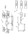
- Fig. 1 shows a system 10 for image object segmentation and tracking according to one embodiment of the invention.
- System 10 includes a user interface 11, a modified adaptive resonance theory -2 (M-ART2) subsystem 12, a correlative auto-predictive search (CAPS) subsystem 14, an edge energy derivation subsystem 16 and an active contour modelling subsystem 18.
- the M-ART2 subsystem 12 serves to detect scene changes in a sequence of image frames.
- the CAPS subsystem 14 serves to identify an object in a given image frame.
- the CAPS subsystem also serves to track the object among a sequence of input image frames. A motion vector of the tracked object is maintained.
- the edge energy subsystem 16 serves to calculate the edge energy for an image object to be modelled.
- the active contour modelling subsystem 18 serves to segment an image object and accurately model an edge boundary of the image object being tracked.
- a host computer system for embodiments of the invention typically includes a display monitor, a keyboard, a pointing/clicking device, one or more processors or multiprocessors, random access memory (RAM), a non-volatile storage device such as a hard disk drive, and other devices such as a communication or network interface (e.g., modem; ethernet adapter), a transportable storage media drive, such as a floppy disk drive, CD-ROM drive, zip drive, bernoulli drive or other magnetic, optical or other storage media.
- RAM random access memory
- non-volatile storage device such as a hard disk drive
- other devices such as a communication or network interface (e.g., modem; ethernet adapter), a transportable storage media drive, such as a floppy disk drive, CD-ROM drive, zip drive, bernoulli drive or other magnetic, optical or other storage media.
- the various components interface and exchange data and commands through one or more busses.
- the computer system receives information by entry through the keyboard, pointing/clicking device, a network interface or another input device or input port.
- the computer system may be any of the types well known in the art, such as a mainframe computer, minicomputer, or microcomputer.
- To speed up computations, (e.g., convolutions, correlations) parallel processing may be implemented.
- Fig. 2 shows a system flow chart of a method 20 for tracking and segmenting an image object according to an embodiment of this invention.
- Input to the method at steps 22 and 24 are initial edge points and an initial image frame.
- the initial edge points are selected manually by an operator using a conventional video editing application interface.
- the edge points are derived automatically and fed into a method embodiment of this invention.
- the initial image frame is processed at step 26 using a modified applied resonance theory -2 (M-ART2) process to define clusters of image pixels.
- M-ART2 modified applied resonance theory -2
- the M-ART2 process is described below in a separate section.
- the edge energy of the input edge boundary is derived.
- an active contour model is applied to segment the edge boundary and accurately model the object boundary.
- the active contour model is described below in a separate section.
- the modelled image boundary is output. In some embodiments the output is written to a buffer, a file, and/or to a display.
- Iterative processing then is performed for subsequent image frames.
- each image frame is processed.
- image frames are periodically or aperiodically sampled.
- the next image frame to be processed is input to the method implementation 20.
- the M-ART2 method is performed to identify whether there has been a scene change. If a scene change is detected at step 44, then the method 20 is complete, or is re-initialized to track another image object. If a scene change has not occurred, then the image object is identified from the image frame using a two-dimensional correlative auto-predictive search (2D-CAPS) process at step 46.
- 2D-CAPS two-dimensional correlative auto-predictive search
- the tracking method 20 terminates or re-initializes for tracking another object. If the object is identified, then the edge energy for the object boundary is derived at step 50. Then at step 52 an active contour model is applied to segment the image boundary and accurately model the object boundary. At step 54 the modelled image boundary is output. As described above for the initial image frame, in some embodiments the output is written to a buffer, a file, and/or to a video screen. The process then repeats steps 40-54 for another image frame. As a result, an image object is segmented and tracked over many image frames.
- the modified adaptive resonance theory - 2 (“modified ART-2") subsystem 12 performs pattern learning and recognition on a sequence of input image frames.
- the M-ART2 subsystem 12 processes a current image frame 60 grouping the image frame contents into clusters 66.
- the image frame 60 is formed by an array of image pixels P.
- the image pixels are arranged into y rows and x columns.
- the image pixels are color image pixels coded according to a standard red, green, blue coding scheme (e.g., NTSC), a standard yellow, magenta, cyan and black coding scheme (YMCK), a standard luminosity, chrominance, brightness coding scheme (e.g., YUV) or some other color coding scheme.
- a standard red, green, blue coding scheme e.g., NTSC
- YMCK yellow, magenta, cyan and black coding scheme
- a standard luminosity, chrominance, brightness coding scheme e.g., YUV
- Each image frame is a set of data points.
- Each pixel is a data point.
- a data point is referred to herein as an input vector.
- Input vector P ij corresponds to pixel P (x i ,y j ) which for an RGB coding scheme has a value (R,G,B).
- the M-ART2 subsystem 12 processes a sequence
- Each cluster 66 is a learned or a recognized pattern.
- a first set of input data i.e., an initial image frame
- the patterns are learned.
- subsequent sets of data points e.g., subsequent images in a sequence of image frames
- the patterns previously learned may be used.
- data points for a current set of data points (image frame) are tested to try and recognize the prior patterns in the new set of data points.
- the process for analyzing the subsequent sets of data points is a recognition process. During the recognition process, the previous learned patterns also are updated and modified based upon the new data.
- a flow chart of the M-ART2 process 26/42 for pattern learning and recognizing commences at step 76. If the current image frame is an initial image frame, then at step 78 various parameters are reset. Further, if the current image frame is an initial image frame then there are no clusters that have been started.
- the current image frame 60 is processed in an iterative manner (step 80).
- step 82 an initial set of prototype vectors for this processing iteration of the current image frame is obtained.
- the prototype vector is a weighted centroid value based upon a history of input vectors allocated to the corresponding cluster.
- the process for allocating input vectors into clusters is performed for each input vector (step 84). Such process is based upon a minimum distance measure. In various embodiments an euclidean distance, an absolute distance or some other distance measure is used. In one embodiment the euclidean distance is used. An input vector is allocated to a cluster to which it has a minimal euclidean distance with the cluster's prototype vector. At step 86, the prototype vector closest to the input vector is found. As a self-organizing control for allocating data into clusters, a vigilance parameter, also referred to herein as a vigilance value, is used. A vigilance test is performed at step 88.
- a new cluster is defined at step 90.
- the input vector is assigned to such new cluster and becomes the initial prototype vector for such new cluster. If the minimum euclidean distance is less than the vigilance value, then the input vector is assigned to the cluster corresponding to the closest prototype vector at step 92. Thus, an input vector is allocated to a pre-existing cluster or a new cluster.
- the first input vector will define an initial prototype vector for a first cluster.
- the minimum distance between the next input vector and the prototype vectors will be to the first prototype vector (since at this point in the example there is only one prototype vector). If such minimum distance exceeds the vigilance value, then the second input vector becomes an initial prototype vector for a second cluster. If, however, such minimum distance is within the vigilance value distance, then the second input vector is allocated to the first cluster.
- the prototype vector for such first cluster is modified at step 94.
- the influence of the new input vector in the cluster has a weighted influence on the prototype vector of the cluster.
- the weight is proportional to the number of input vectors in the cluster, and thus, corresponds to a statistical centroid.
- This process is used for allocating each input vector of the current image frame. Once all the input vectors have been allocated in a given iteration, testing is performed to determine whether another iteration is needed and whether outlier clusters are present.
- one or more initial clusters are defined as above.
- An iterative process is used, however, to achieve a self-stabilizing quality to the clusters. Specifically, once the entire data set has been processed, allocating the input vectors into clusters, another iteration of allocating the input vectors into clusters is performed. Prior to performing another iteration, however, the clusters are analyzed for quantity in an outlier test (see step 96). According to such test, any cluster having less than a prescribed threshold number of input vector members is discarded. More specifically the prototype vector is discarded and thus not used in finding a minimum distance to input vectors during a subsequent iteration. The input vectors in the discarded cluster are considered to be outliers (e.g., noise).
- outliers e.g., noise
- a data set including 30,000 data values including 30,000 data values.
- a first cluster has 20,000 members
- a second cluster has 8,000 members
- a third cluster has 1985 members
- a fourth cluster has 15 members.
- the prescribed threshold value is 64. Because cluster 4 has less than 64 input vector members, it is discarded. It is expected that many of the input vectors in this fourth cluster will be allocated into another cluster during a subsequent reiteration. Note that this is an example, and that the threshold value may be prescribed as a matter of design, or based upon empirical analysis.
- the prototype vectors from the remaining clusters of the prior iteration are retained (step 82 of next iteration).
- the prototype vectors from the first three clusters are retained, while the prototype vector from the fourth cluster is discarded.
- Each input vector then is re-allocated to a cluster during this subsequent iteration by determining the prototype vector to which it has a minimum euclidean distance. If such minimum distance is less than the vigilance value, then the input vector is allocated to the cluster corresponding to that prototype vector. If such minimum distance exceeds the vigilance value, then the input vector defines a prototype vector for a new cluster. According to various embodiments, either the same or a different vigilance value is used during the subsequent iterations.
- the prototype vector i.e., weighted centroid
- the prototype vector i.e., weighted centroid
- the number of input vectors in the cluster is not reset, but remains at its last count from the prior iteration.
- the weighting influence of the current input vector is less during the subsequent iteration than during the prior iteration.
- any cluster having fewer than a prescribed threshold number of input vector members is discarded (step 96).
- the clusters then are tested for convergence (step 98) to see if the number of input vector members in each cluster has significantly changed. If the number has not changed significantly, then the iterative process is complete. In this sense, the process is self-stabilizing. If a cluster was discarded for such iteration, such discarded cluster is considered to be an outlier and the members are considered as noise.
- the number of cluster members is considered to change significantly if it has changed by more than a prescribed number of data points or prescribed percentage, whichever is larger. Such number and percentage are defined empirically. If the number of members has changed significantly then a new iteration is performed (step 80). In the new iteration, the remaining (e.g., non-discarded) prototype vectors from the immediately prior iteration are used as the initial prototype vectors for each remaining cluster (step 82). The iterations continue until, either the number of members in each cluster is not changed significantly (convergence test at step 98), or a prescribed maximum number of iterations has occurred. Such maximum number of iterations is determined as a matter of design or empirically.
- the prototype vectors correspond to the final prototype vectors from the preceding image frame processed among the sequence of image frames being processed.
- Each input vector in such current image frame is allocated to a cluster by determining the prototype vector to which it has a minimum euclidean distance (step 86). If such minimum distance is less than the vigilance value (step 88), then the input vector is allocated to the cluster corresponding to that prototype vector (step 92). If such minimum distance exceeds the vigilance value, then the input vector defines a prototype vector for a new cluster (step 90). A new cluster corresponds to a new prototype pattern.
- either the same or a different vigilance value is used for the subsequent image frames in the sequence relative to that used for an initial image frame.
- the vigilance value is increased for the subsequent data sets, relative to that for the initial data set.
- the prototype vector i.e., centroid
- the number of input vectors in the cluster is held over from the processing of the prior image frame.
- the prototype vector is a weighted centroid based upon multiple iterations of multiple image frames in a sequence of image frames.
- step 96 the clusters are analyzed for quantity in the outlier test. Any cluster having less than a prescribed threshold number of input vector members is discarded as described above for the initial data set. For the subsequent iteration the prototype vectors from the remaining clusters of the first iteration are retained. Each input vector then is re-allocated to a cluster during the subsequent iterations in the same manner as described above.
- the starting prototype vectors for allocating input vectors of a current data set are the final prototype vectors obtained during processing of the immediately prior data set. Further the count of the number of input vectors in a clusters is held over from prior iterations and prior image frames.
- New clusters defined as the sequence of data clusters continue correspond to new prototype patterns. New prototype patterns may occur in an image sequence, for example, due to an image object insertion, deletion or change.
- a scene change is determined by tracking a cluster change ratio from image frame to image frame. Specifically, after the iterative processing of input vectors for a current image frame is complete, the cluster rate of change for that image frame is derived. Cluster rate of change is derived in a preferred embodiment using the following equation: where,
- N k f-1 is simply zero.
- a scene change is identified at step 44 (see Fig. 3) when the cluster change ratio for an image frame f exceeds a prescribed value, (e.g., 5%-10%).
- the prescribed value is determined empirically or be design and may exceed the example values of 5%-10%.
- the method 20 terminates, or is restarted (at step 22) with the current image frame f set to be an initial frame.
- Image frame f then is re-processed as the current frame. Since it is an initial frame, parameters are reset at step 78. Specifically, the prototype vectors are discarded. Thus at step 82 there are no prototype vectors.
- the CAPS process is executed for image frames following an initial image frame.
- the object to be tracked has been defined during processing of the initial image frame.
- the object location is updated (by the CAPS process) during processing of subsequent image frames.
- the initial object or the updated object from the prior frame serves as a template for locating the object in the current image frame.
- the object being tracked serves as a template 108 while the current image frame serves as a search area 110.
- the template 108 is overlaid onto a window 112 within the search area 110.
- a motion vector is maintained which identifies the change in location of the object from one frame to the next. In some embodiments the motion vector derived from the previous frame is used to select a starting window 112.
- the template 108 data points are compared to the window's 112 data points to determine if the data points correlate to a desired degree. If they do, then a match for the template has been found.
- a template formed by 'k' rows of 'p' data points may be placed over ( m-k+1) * (n-p+1 ) potential windows 112.
- an effective step size is derived from the template.
- a step size along a first axis 114 is derived and a step size along a second axis 116 is derived.
- the template 108 is moved along either or both of the first axis 114 and second axis 116 by the corresponding first axis step size or second axis step size.
- the template 108 is compared to the various windows 112 of the search area 110 at the step size increments during a fast search process.
- the comparison is a correlation function of the template 108 and the window 112 and results in a correlation coefficient.
- Any window 112 in which the correlation coefficient with the template 108 is found to exceed a specific value is a local match for the template.
- the specific value is the cut value times a threshold value.
- a full search then is performed in the vicinity of any location which is a local match.
- a full search of such vicinity encompasses performing a correlation between the template and every potential search area window between the local match location window and the windows at the prior and next step in each of the horizontal and vertical axes. For example, if the horizontal step size is 3 pixels and the vertical step size is 4 pixels, then correlations are performed for windows ⁇ 1 pixel and ⁇ 2 pixels along the horizontal axis and ⁇ 1 pixel, ⁇ 2 pixels and ⁇ 3 pixels along the vertical axis. In addition correlations are performed for windows off the axes within the area delineated by the step sizes.
- the template 108 itself is analyzed. Referring to Fig. 6, at a first step 120 the template 108 is padded with additional data points to achieve a padded template.
- a padded template For circular padding, multiple copies of the template 108 are used to increase the template size. The number of copies may vary for differing embodiments. In a preferred embodiment there are at least 9 full copies of the template in the circularly padded template.
- a padded template is achieved by linear padding.
- data points are added in which each data point has a common value. The common value is a padding constant. In one embodiment the padding constant may be 0 or another fixed value. In a preferred embodiment the padding constant is derived from the data values of the various data points which make up the template 108.
- an average data value is derived for all the temple 108 data points using any of various averaging techniques.
- This average value serves as the padding constant.
- the added data points are pixels and the padding constant is a pixel intensity and/or color.
- the center window of the padded template formed by linear padding also is formed by the original template 108.
- the template 108 is correlated to various windows of the padded template. Because the center of the padded template equals the original template 108, it is known that the correlation between the template 108 and the center window is 1.0. Thus, that correlation need not be calculated. It is already known. For a two dimensional analysis, a correlation between the original template 108 and windows of the padded template are derived for windows along either of such axes 114, 116 moving in either direction away from the center window.
- the step size for selecting adjacent window to evaluate is one data point. Consider for example a template which is 40 pixels by 60 pixels and a padded template which is 120 pixels by 180 pixels. The step size is one pixel.
- step 122 a correlation is performed between the template and the select windows. As the selected window changes along the first axis 114 in the first direction, the resulting correlation coefficient is likely to decrease below 1.0. Eventually there will be a window where the correlation coefficient falls to a prescribed cut-off value. Such cut-off value may vary for differing embodiment, but preferably is less than a threshold value which identifies an estimated match between a window and the template. A window will be found in the padded template in each direction along axis 114 where the cut-off criteria is met.
- correlations are performed for windows along the axis 114 away from the center window in each direction until a window is identified in such direction where the correlation coefficient intersects the cut-off value.
- the first axis step size is derived from the width along the first axis 114 between windows which have a correlation to the template 108 equal to or less than the prescribed cut-off value.
- the step size along the first axis 114 is a fraction of the width. In a preferred embodiment, one-half the width is taken as the step size for the given axis. In other embodiments, the step size is taken as the entire width or some other fraction of the width.
- steps 126 and 128 the correlations are repeated along the second axis 116 in two opposing directions to find a width along the second axis 116.
- a cut-off point found in each direction from the center window along the second axis 116.
- the distance between those two windows in data points is the width along the second axis.
- a fraction of this distance is taken as the step size for the corresponding axis (e.g., first axis, or horizontal, step size; second axis, or vertical, step size).
- one-half the width is taken as the step size.
- the step size is taken as the entire width or some other fraction of the width.
- the step size along the second axis 116 is derived in the same manner as the step size along the first axis 114.
- the step sizes are referred to herein as correlative auto-predictive search ('CAPS') step sizes.
- a fast search is performed comparing the template 108 to the search area 110. It is a fast search in the sense that not every potential window of the search area is compared to the template.
- the search area 110 is shown as an array of data points 74, 75 such as image pixels points.
- the two CAPS step sizes are used for selecting windows from the search area 110 to be compared to the template.
- the data points in the search area 110 about which the template is centered during successive steps are designated with an open circle and part number 75. Other data pints in the points which are not center points are designated as a data point 74.
- the template 108 (see Fig. 5) is overlaid to a starting window 112 of the search area 110.
- the starting window can be any window of the search area.
- the starting window 112 is selected by predicting the object location with the motion vector, derived for the previous frame.
- a linear prediction calculation is implemented, although other more complex prediction algorithms also may be used.
- a correlation is performed between the template 108 and the starting window and every +/- x-th window along the first axis 114, where x is the first axis step size.
- the template is shifted along the horizontal axis 114 by x data points at a time. More specifically, a center point 77 of the template 108 coincides with a given pixel 75 for a given iteration. The template then is moved to center over another data point 74 that is x points away from the given pixel 75 along the horizontal axis 114. The template 108 is moved in each direction along the axis 114 using the first step size of x.
- a correlation is performed at each step.
- step 140 the shifting along the first axis 114 and testing of windows is performed for a template center point repositioned over every y-th row of data points. Specifically, once the initial row of the search area has been tested, the template 108 is moved along the second axis 116 to another row that is y data points away, where y is the second axis step size. This next row then is tested by shifting along the first axis 114 using the first axis step size. A correlation is performed at each iteration. Then another row is tested which is y data points away along the second axis 116.
- the template is shifted by the second step size along the second axis 116 and by the first step size along the first axis 114 to select windows to be tested during the fast search.
- the window location for any correlation which resulted in a correlation coefficient which is greater than or equal to the product of the cut value times a predetermined threshold value is considered a local match.
- the cut value is the same for each axis. Where the cut value used along one axis differs from the cut value used along the other axis, either cut value may be used. Alternatively, an average of the cut values may be used.
- the threshold value is a predetermined value and signifies the minimum correlation coefficient acceptable to designate a window as being a match for the template. Typical values are 0.8 and 0.9.
- the specific value may vary based upon the search area or type of date. The specific value may be determined empirically for different types of data or search area characteristics.
- a local full search is performed about each of the local matches. For a given window of the search area 110 which is a local match, the windows which are within a 2-dimensional area bounded by the step sizes (for the respective axes) are tested by a local full search. Note that the windows which are exactly a step size away along either axis 114, 116 were already tested during the fast search. To do the local full search we test all the intermediary windows in the area between the local match and the windows plus or minus one step size away along either axis 114, 116.
- the windows having a center point which are +/- 0, 1, 2, ..., x-1 data points away from the locally matched window along the first axis, and +/- 0, 1, 2, ..., y-1 data points away from the locally matched window along the second axis are tested during the full search.
- the local match need not be recorrelated.
- the window corresponding to the local match has a center data point 146.
- the template is moved at a step interval of one data point in either direction along either axis up to but not including the data point which in one step size away.
- the windows tested during the local full search will have a center data point 148.
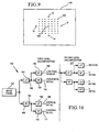
- Fig. 9 shows all the center points 148 for a given local full search as black dots for an implementation in which the first axis step size is four and the second axis step size is four.
- Fig. 9 shows the nearby center points from the fast search as open dots 75.
- a correlation is performed between the template 108 and each window in the vicinity of the local match.
- the vicinity shown in Fig. 9 in which the step is four there are 48 additional windows tested. Any of the additional 48 windows or the local match which has a correlation coefficient which equals or exceeds the threshold value is a match of the template.
- the windows where the correlation coefficient exceeds the threshold value only the window or windows having the highest correlation coefficient(s) are selected as matched. For example, one or more windows may have the same correlation coefficient which is highest.
- the windows corresponding to the top 'n' correlation coefficients may be selected, where each window correlation coefficient also exceeds the threshold value.
- the corresponding window in the search area is the object being tracked.
- the relative position of the object within the search area 110 for the current image frame is compared to the relative position of the object in the search area for the prior image frame.
- the motion vector is derived/updated from the relative positions to define the movement of the object.
- the vector is a linear vector derived from respective mid-points of the object from the two image frames.
- a more complex vector analysis is performed to identify rotation or other two-dimensional or three-dimensional motion of the object being tracked.
- the area of the image frame corresponding to the template match is output to the edge energy modelling subsystem 16, where the edge potential energy of the object boundary is derived.
- a set of data points along the periphery of the template match is sampled to serve as an estimate of the current image object boundary. Such estimate is input to the active contour modelling subsystem 18.
- the correlation coefficient for a correlation between two data sets 'a' and 'b' is defined below.
- the data set 'a' is the template 108.
- the data set 'b' is a window of the padded template (or of a rotational offset of the padded template) for the process of finding the CAPS step sizes.
- the data set 'b' is a window of the search area 110 (or of a rotational offset of the search area) for the process of identifying candidate locations, potential template matches or template matches.
- Each of data sets 'a' and 'b' may be a matrix, image or another set of data points.
- edge energy is generated at steps 28 and 50. More particularly, it is edge potential energy which is derived.
- Various measures of potential energy may be implemented.
- a multiple level wavelet detection algorithm is used to extract high frequency components of an image. The high frequency details are analyzed to identify image object edges.
- Haar wavelet detection is used.
- the input to be processed to derive edge potential energy is an image.
- the image is the entire image frame.
- the image is an image object (e.g., the template match area found by the CAPS subsystem 14).
- the derived edge potential energy is an array of potential energy for each data point (pixel) of the image.
- the input image is decomposed by filtering the image with a quadrature mirror filter (QMF) pair which brings out the image details, while simultaneously smoothing the image.
- the QMF pair includes a high pass filter for bringing out the image details, and a low pass filter for smoothing the image.
- a multiple level QMF decomposition 150 of an image frame 152 is shown.
- the image frame 152 is passed through a low pass filter 154 and a high pass filter 156 to obtain a low pass component 158 and a high pass component 160. These components, in turn, are filtered.
- the low pass component 158 is passed through a low pass filter 162 and a high pass filter 164.
- the output of low pass filter 162 is lowpass residue 166.
- the output of high pass filter 164 is the horizontal detail 165 of the image frame 152.
- the high pass component 160 is passed through a low pass filter 168 and a high pass filter 170.
- the output of the low pass filter 168 is the vertical detail 169 of the image frame 152.
- the output of the high pass filter 170 is the diagonal detail 171 of the image frame 152.
- the low pass residue 166 and the three detailing images 165, 169, 171 are the first level QMF decomposition of the image frame 152.
- a second level QMF decomposition 172 also is performed in which the low pass residue 166 is input similarly through two stages of low pass and high pass filters to achieve a second-level, low-pass residue and three detailing images (horizontal detail, vertical detail and diagonal detail).
- the same filters may be used in the second level decomposition as were used in the first level decomposition.
- the low pass residue 166 is merely input to filters 154, 156 instead of the image frame 152.
- the high pass filtering function is a wavelet transformation ( ⁇ ), while the low pass filtering function is a scaling function ( ⁇ ) corresponding with the wavelet.
- the scaling function causes smoothing, while the three wavelets bring out the image details.
- Two dimensional wavelets are defined as tensor products of the one-dimensional wavelets.
- scaling may be varied from one level of decomposition to another, in one embodiment such scaling is not varied.
- a first level QMF decomposition is performed.
- the low pass residue 166 of the first level decomposition is analyzed without further downsampling.
- additional levels of decomposition may be obtained by passing the low pass residue of the prior level through a two stage filtering process (similar to that for the prior levels).
- the low pass residue For any given level of decomposition there are four images: the low pass residue, the vertical detail, the horizontal detail and the diagonal detail.
- the horizontal and vertical detail are gradients of the image along x and y axes. The magnitude of the image is taken at every level of decomposition.
- the diagonal details have been omitted in one embodiment, because they did not contribute significantly.
- up to five levels of decomposition are used for each color component of the image frame, in which the low pass residue from the prior stage is input to the filters 154, 156 to generate image details and residue for the current stage.
- the integration of the multiple levels and multiple channel (color component) data is guided by their principle component.
- the ratio of multiple-level edge gradients is selected as 1:2:4:8:16 for the five levels of decomposition. With respect to the color components (Y, Cr, Cb), edge gradient ratios of 1:1:1 are used.
- EPE edge potential energy
- the overall edge potential energy for the entire frame, inclusive of all color components is the weighted sum of the energy from the different color components.
- R,G and B color components or those of another color component model may be used.
- the weighting factor may vary depending on the color components model being used.
- the total edge potential energy is an array having an energy value for each pixel of the image processed.
- the edge potential energy is input to the active contour model for use in object segmentation.
- the edge energy is input to the CAPS process.
- the edge energy is being used to predict where the object being tracked is located in a current image frame.
- the "Generate Edge Energy" step 50 is executed prior to the CAPS step 46 (see Fig. 2).
- the edge potential energy is derived before or after the CAPS model executes.
- a predicted location for the image object may be derived with the edge potential energy as an input to the CAPS subsystem 14.
- the image being processed for edge potential energy is the template matched portion of the image frame.
- the image boundary i.e., edge
- the active contour modelling subsystem 18 performs such segmentation.
- an active contour model is applied to segment the image object boundary.
- Input to the active contour model is the derived total edge potential energy and a current image object boundary.
- the total edge potential energy is derived at step 50 (see Fig. 2).
- the current image object boundary is the boundary input to the system at step 22 (see Fig. 2).
- the set of data points for the current image object boundary are used by the active contour model at step 30 (see Fig. 2).
- the current image object boundary is derived by the CAPS subsystem 14, as described above.
- the set of data points for the current image object boundary are used by the active contour model at step 52 (see Fig. 2).
- a flow chart 192 of the active contour model includes a first step 194 at which edge points are received by the active contour modelling subsystem 18.
- the number of input edge points may vary.
- the edge points which are too close together are eliminated, (i.e., less than a first threshold distance apart). In one embodiment points are considered too close together when they are less than 2.5 pixels apart. In other embodiments the distance may be smaller or larger.
- additional points are added by interpolation where the adjacent points are too far apart, (i.e., greater than a second threshold distance apart). In one embodiment points are considered too far apart together when they are greater than 6.0 pixels apart. In other embodiments the distance may be smaller or larger than 6.0 while being larger than the first threshold distance.
- the active contour modelling subsystem 18 performs global relaxation on the N current edge points. To do so, for each current edge point, M candidate points are selected from a box around the current edge point. In one embodiment M equals 4, although in various embodiments the number of candidate points may vary. In one embodiment a 5x5 box is used. However, the size of the box may vary. A larger box leads to a more flexible contour, but more computation time.
- the shape of the box may be square, rectangular or another shape.
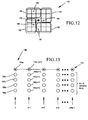
- a 5x5 box 174 of pixels surrounding the current edge point 176 is divided into four regions 178, 180, 182, 184. Within each region there are 6 pixels. One of those 6 pixels is selected in each region to be a candidate pixel ('point') which may potentially replace the current edge point 176 as an object boundary edge point. Thus, 4 candidate points 186-189 are selected for each current edge point 176. In alternative embodiments a different number of candidate points, or another method of selecting candidate points, may be used.
- the candidate point is the pixel among the 6 potential points which has the highest edge potential energy.
- M e.g., four
- N e.g., 5 N
- a travel algorithm is applied to the current edge points with the alternative candidate points to select an optimal contour path.
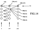
- Fig. 13 shows a travel path diagram for the possible contours.
- M+1 e.g., 5 points in each column.
- the five points correspond to a current edge point 176 and four candidate edge points 186, 189 for such current edge point 176.
- the number of points in each row corresponds to N.
- a starting location 190 on the current contour is selected.
- a distance value e.g., in pixels
- a first segment of the path is constructed by advancing to one of the M+1 points in the adjacent column s+1.
- One choice is to step to point 176(s+1).
- Another choice is to step to candidate point 186(s+1).
- the others choices include 187(s+1), 188(s+1) and 189(s+1). Only one choice is selected.
- the selected point is preserved along with a distance of how far such point is from the current point in column s+1.
- Respective paths starting from point 187s, 188s and 189s, respectively are constructed in the same manner.
- the M+1 resulting paths then are compared to see which one is the most optimal path, (e.g., most difference in energy relative tot he current contour 173).
- the terms d i 0 and d i 1 correspond to tension in the contour.
- the term d i 2 corresponds to stiffness for keeping the shape of the modelled contour similar to the current contour.
- the term d i 3 corresponds to pressure to keep the candidate contour close to the current contour.
- the optimal contour is the one having the optimal ⁇ E. In one embodiment this is the maximum ⁇ E. In other embodiments negative TEPE is used instead, so optimum becomes the minimum ⁇ E.
- the optimal contour is a polygon.
- the points identified at step 202 selected from the travel algorithm may or may not be on the actual smooth object boundary.
- fine tuning is performed at step 204.
- Each segment of the optimal contour includes the points selected using the travel algorithm as end points, along with the pixels in between.
- the pixels in between although not part of the travel problem are part of the input image being processed.
- the pixel along the segment having the highest edge potential energy is selected as the most reliable point of such group for being on the actual object boundary.
- a most reliable point is selected for each segment of the polygon (i.e., optimal contour path output from the travel algorithm). Points then are selected to be filled in between the most reliable points using the criteria: (i) a new point should be 8 connected to a previously selected boundary point, and (ii) the distance of the new boundary point to the next boundary point should be less than the distance from the previous boundary point to the next boundary point.
- the active contour process is repeated with the object boundary of the prior iteration being the current edge points.
- Global relaxation then is performed again at step 200 to select alternative candidate points for the current edge points.
- the travel algorithm is reapplied at step 202 , followed by fine tuning at step 204.
- an iteration count is tested to determine if a maximum number of iterations have been executed. If a maximum number of iterations has occurred, then the edge points making up the fine tuned boundary are the image object boundary points output at step 54 (see Fig. 2). If not, then at step 208 the contour is checked to see if it has changed from the prior iteration. If it has not changed then the edge points making up the fine tuned boundary are the image object boundary points. If the contour has changed, then the process is repeated commencing at step 200 with the global relaxation process.
- Exemplary implementations of the object segmentation methods include, but are not limited to video encoding, video editing and computer vision.
- the segmentation and modelling may be performed in the context of MPEG-4 video encoding and content based video editing in which video objects from different video clips are grouped together to form a new video sequence.
- the segmentation and modelling may be performed with limited user assistance to track a target (e.g., military or surveillance context). Once the target is locked with user assistance, the tracking and segmentation methods automatically provide information to follow the target.
- a target e.g., military or surveillance context
Landscapes
- Engineering & Computer Science (AREA)
- Theoretical Computer Science (AREA)
- Multimedia (AREA)
- Physics & Mathematics (AREA)
- General Physics & Mathematics (AREA)
- Computer Vision & Pattern Recognition (AREA)
- Software Systems (AREA)
- Artificial Intelligence (AREA)
- Health & Medical Sciences (AREA)
- Computing Systems (AREA)
- Databases & Information Systems (AREA)
- Evolutionary Computation (AREA)
- General Health & Medical Sciences (AREA)
- Medical Informatics (AREA)
- Image Analysis (AREA)
- Image Processing (AREA)
Applications Claiming Priority (2)
| Application Number | Priority Date | Filing Date | Title |
|---|---|---|---|
| US09/323,501 US6546117B1 (en) | 1999-06-10 | 1999-06-10 | Video object segmentation using active contour modelling with global relaxation |
| US323501 | 1999-06-10 |
Publications (2)
| Publication Number | Publication Date |
|---|---|
| EP1061748A2 true EP1061748A2 (de) | 2000-12-20 |
| EP1061748A3 EP1061748A3 (de) | 2003-03-26 |
Family
ID=23259467
Family Applications (1)
| Application Number | Title | Priority Date | Filing Date |
|---|---|---|---|
| EP00201976A Withdrawn EP1061748A3 (de) | 1999-06-10 | 2000-06-05 | Videoobjektsegmentierung unter Verwendung von Aktivkonturmodellisierung mit globaler Relaxation |
Country Status (3)
| Country | Link |
|---|---|
| US (3) | US6546117B1 (de) |
| EP (1) | EP1061748A3 (de) |
| JP (1) | JP2001034771A (de) |
Cited By (6)
| Publication number | Priority date | Publication date | Assignee | Title |
|---|---|---|---|---|
| AU769886B2 (en) * | 2000-03-01 | 2004-02-05 | Canon Kabushiki Kaisha | Segmenting an image |
| WO2004044830A1 (en) | 2002-11-12 | 2004-05-27 | Nokia Corporation | Region-of-interest tracking method and device for wavelet-based video coding |
| FR2896605A1 (fr) * | 2006-01-24 | 2007-07-27 | Survision Soc Par Actions Simp | Procede et systeme d'identification et de poursuite automatique d'un objet dans un film pour la videosurveillance et le controle d'acces |
| GB2485359A (en) * | 2010-11-10 | 2012-05-16 | J T Consultancy Ltd | A Simulator Including A Controller And A Means For 3-Dimensional Position Recognition Using Correlation |
| CN103136759A (zh) * | 2013-03-26 | 2013-06-05 | 长春工业大学 | 基于仿生优化脑白质mri图像分割的方法 |
| CN120783136A (zh) * | 2025-09-05 | 2025-10-14 | 湖南大学 | 一种鲁棒高精度的机器人手术视觉任务执行方法 |
Families Citing this family (133)
| Publication number | Priority date | Publication date | Assignee | Title |
|---|---|---|---|---|
| US6993186B1 (en) | 1997-12-29 | 2006-01-31 | Glickman Jeff B | Energy minimization for classification, pattern recognition, sensor fusion, data compression, network reconstruction and signal processing |
| US6546117B1 (en) * | 1999-06-10 | 2003-04-08 | University Of Washington | Video object segmentation using active contour modelling with global relaxation |
| WO2000042772A1 (en) * | 1999-01-15 | 2000-07-20 | Koninklijke Philips Electronics N.V. | Coding and noise filtering an image sequence |
| JP4224882B2 (ja) * | 1999-02-09 | 2009-02-18 | ソニー株式会社 | データ処理装置およびデータ処理方法 |
| JP2000339450A (ja) * | 1999-05-26 | 2000-12-08 | Sony Corp | 画像処理方法及び画像処理装置 |
| JP2001188910A (ja) * | 1999-10-22 | 2001-07-10 | Toshiba Corp | 画像の輪郭抽出方法、画像からの物体抽出方法およびこの物体抽出方法を用いた画像伝送システム |
| US7027650B2 (en) * | 1999-12-10 | 2006-04-11 | Christian Williame | Dynamic computing imagery, especially for visceral osteopathy and for articular kinetics |
| JP4633992B2 (ja) * | 2000-04-11 | 2011-02-16 | エヌエックスピー ビー ヴィ | データサンプルと別のデータサンプルの補間との間の類似度を決定する方法 |
| US20030079184A1 (en) * | 2000-05-05 | 2003-04-24 | International Business Machines Corporation | Dynamic image storage using domain-specific compression |
| US6721453B1 (en) * | 2000-07-10 | 2004-04-13 | The Board Of Trustees Of The University Of Illinois | Method and apparatus for processing an image of an agricultural field |
| JP4564634B2 (ja) * | 2000-08-14 | 2010-10-20 | キヤノン株式会社 | 画像処理方法及び装置並びに記憶媒体 |
| US20020061062A1 (en) * | 2000-11-22 | 2002-05-23 | O'brien Royal | Filtering system and method for digital interactive streams |
| US6785419B1 (en) * | 2000-12-22 | 2004-08-31 | Microsoft Corporation | System and method to facilitate pattern recognition by deformable matching |
| US6937760B2 (en) * | 2000-12-28 | 2005-08-30 | University Of Washington | Interactive frame segmentation with dynamic programming |
| DE10111661A1 (de) * | 2001-03-09 | 2002-09-12 | Philips Corp Intellectual Pty | Verfahren zum Segmentieren einer in einem Objekt enthaltenen dreidimensionalen Struktur, insbesondere für die medizinische Bildanalyse |
| JP2002288653A (ja) * | 2001-03-23 | 2002-10-04 | Minolta Co Ltd | 画像処理装置,方法,プログラム及び記録媒体 |
| US8666172B2 (en) * | 2001-03-29 | 2014-03-04 | Intel Corporation | Providing multiple symmetrical filters |
| US7190832B2 (en) * | 2001-07-17 | 2007-03-13 | Amnis Corporation | Computational methods for the segmentation of images of objects from background in a flow imaging instrument |
| JP2003153269A (ja) * | 2001-11-08 | 2003-05-23 | Mitsubishi Electric Corp | 動きベクトル検出装置、それを複数用いた動きベクトル検出システムおよび動きベクトル検出方法 |
| US6891549B2 (en) * | 2002-01-11 | 2005-05-10 | Applied Materials, Inc. | System and method for edge enhancement of images |
| CA2436400A1 (en) * | 2002-07-30 | 2004-01-30 | Abel G. Wolman | Geometrization for pattern recognition, data analysis, data merging, and multiple criteria decision making |
| GB0221144D0 (en) * | 2002-09-12 | 2002-10-23 | Snell & Wilcox Ltd | Image processing using vectors |
| US7477781B1 (en) * | 2002-10-10 | 2009-01-13 | Dalsa Corporation | Method and apparatus for adaptive pixel correction of multi-color matrix |
| US7057664B2 (en) * | 2002-10-18 | 2006-06-06 | Broadcom Corporation | Method and system for converting interlaced formatted video to progressive scan video using a color edge detection scheme |
| JP4196845B2 (ja) * | 2003-03-31 | 2008-12-17 | セイコーエプソン株式会社 | 画像処理装置 |
| US20040233233A1 (en) * | 2003-05-21 | 2004-11-25 | Salkind Carole T. | System and method for embedding interactive items in video and playing same in an interactive environment |
| US7606417B2 (en) | 2004-08-16 | 2009-10-20 | Fotonation Vision Limited | Foreground/background segmentation in digital images with differential exposure calculations |
| US7680342B2 (en) * | 2004-08-16 | 2010-03-16 | Fotonation Vision Limited | Indoor/outdoor classification in digital images |
| US7551785B2 (en) * | 2003-07-03 | 2009-06-23 | Canadian Space Agency | Method and system for compressing a continuous data flow in real-time using cluster successive approximation multi-stage vector quantization (SAMVQ) |
| JP2005045404A (ja) * | 2003-07-24 | 2005-02-17 | Ricoh Co Ltd | 画像処理装置、画像処理方法およびプログラム |
| KR100575733B1 (ko) * | 2003-08-26 | 2006-05-03 | 엘지전자 주식회사 | 압축 동영상의 움직임 객체 분할 방법 |
| EP1530156B1 (de) | 2003-11-07 | 2012-03-14 | Mitsubishi Electric Information Technology Centre Europe B.V. | Erfassung visueller Objekte |
| US7430329B1 (en) * | 2003-11-26 | 2008-09-30 | Vidiator Enterprises, Inc. | Human visual system (HVS)-based pre-filtering of video data |
| FR2864300A1 (fr) * | 2003-12-22 | 2005-06-24 | France Telecom | Procede de localisation et de segmentation floue d'une personne dans une image video |
| US7809061B1 (en) | 2004-01-22 | 2010-10-05 | Vidiator Enterprises Inc. | Method and system for hierarchical data reuse to improve efficiency in the encoding of unique multiple video streams |
| US20050185836A1 (en) * | 2004-02-24 | 2005-08-25 | Wei-Feng Huang | Image data processing in color spaces |
| US7447358B2 (en) * | 2004-03-31 | 2008-11-04 | Intel Corporation | Image segmentation using branch and bound analysis |
| US7636489B2 (en) * | 2004-04-16 | 2009-12-22 | Apple Inc. | Blur computation algorithm |
| US7457435B2 (en) | 2004-11-17 | 2008-11-25 | Euclid Discoveries, Llc | Apparatus and method for processing video data |
| WO2010042486A1 (en) * | 2008-10-07 | 2010-04-15 | Euclid Discoveries, Llc | Feature-based video compression |
| US7457472B2 (en) * | 2005-03-31 | 2008-11-25 | Euclid Discoveries, Llc | Apparatus and method for processing video data |
| US7508990B2 (en) * | 2004-07-30 | 2009-03-24 | Euclid Discoveries, Llc | Apparatus and method for processing video data |
| US7436981B2 (en) * | 2005-01-28 | 2008-10-14 | Euclid Discoveries, Llc | Apparatus and method for processing video data |
| US9578345B2 (en) | 2005-03-31 | 2017-02-21 | Euclid Discoveries, Llc | Model-based video encoding and decoding |
| US8902971B2 (en) | 2004-07-30 | 2014-12-02 | Euclid Discoveries, Llc | Video compression repository and model reuse |
| US7158680B2 (en) * | 2004-07-30 | 2007-01-02 | Euclid Discoveries, Llc | Apparatus and method for processing video data |
| US9743078B2 (en) | 2004-07-30 | 2017-08-22 | Euclid Discoveries, Llc | Standards-compliant model-based video encoding and decoding |
| US9532069B2 (en) | 2004-07-30 | 2016-12-27 | Euclid Discoveries, Llc | Video compression repository and model reuse |
| KR101278224B1 (ko) * | 2004-09-21 | 2013-06-24 | 유클리드 디스커버리스, 엘엘씨 | 비디오 데이터를 처리하기 위한 장치 및 방법 |
| JP2006115078A (ja) * | 2004-10-13 | 2006-04-27 | Matsushita Electric Ind Co Ltd | 画像データの信号処理装置及びその方法 |
| ATE534276T1 (de) * | 2005-01-10 | 2011-12-15 | Syngenta Participations Ag | Gerät zur bestimmung der gleichförmigkeit einer saatgutcharge |
| US7715589B2 (en) * | 2005-03-07 | 2010-05-11 | Massachusetts Institute Of Technology | Occluding contour detection and storage for digital photography |
| WO2006106919A1 (ja) * | 2005-03-31 | 2006-10-12 | Nikon Corporation | 画像処理方法 |
| WO2006120840A1 (ja) * | 2005-05-12 | 2006-11-16 | Nec Corporation | 映像コミュニケーションシステム、端末、および画像変換装置 |
| JP2007004709A (ja) * | 2005-06-27 | 2007-01-11 | Toshiba Corp | 対象パターン検出方法及びその装置 |
| US7805005B2 (en) * | 2005-08-02 | 2010-09-28 | The United States Of America As Represented By The Secretary Of The Army | Efficient imagery exploitation employing wavelet-based feature indices |
| EP1938274A2 (de) | 2005-09-12 | 2008-07-02 | D.V.P. Technologies Ltd. | Verarbeitung medizinischer bilder |
| US7787678B2 (en) * | 2005-10-07 | 2010-08-31 | Siemens Corporation | Devices, systems, and methods for processing images |
| GB2431787B (en) * | 2005-10-31 | 2009-07-01 | Hewlett Packard Development Co | A method of tracking an object in a video stream |
| US7706610B2 (en) * | 2005-11-29 | 2010-04-27 | Microsoft Corporation | Segmentation of objects by minimizing global-local variational energy |
| US7692696B2 (en) * | 2005-12-27 | 2010-04-06 | Fotonation Vision Limited | Digital image acquisition system with portrait mode |
| KR100698845B1 (ko) * | 2005-12-28 | 2007-03-22 | 삼성전자주식회사 | 인물 외형 추출 알고리즘을 이용한 영상 편집 방법 및 그장치 |
| US7869043B2 (en) * | 2006-01-06 | 2011-01-11 | Sparta, Inc. | Automated passive skin detection system through spectral measurement |
| IES20060559A2 (en) * | 2006-02-14 | 2006-11-01 | Fotonation Vision Ltd | Automatic detection and correction of non-red flash eye defects |
| US7469071B2 (en) * | 2006-02-14 | 2008-12-23 | Fotonation Vision Limited | Image blurring |
| IES20060564A2 (en) * | 2006-05-03 | 2006-11-01 | Fotonation Vision Ltd | Improved foreground / background separation |
| KR100847136B1 (ko) * | 2006-08-14 | 2008-07-18 | 한국전자통신연구원 | 어깨 윤곽선 추출 방법, 이를 이용한 로봇 깨움 방법 및이를 위한 장치 |
| US8139115B2 (en) | 2006-10-30 | 2012-03-20 | International Business Machines Corporation | Method and apparatus for managing parking lots |
| US8094958B2 (en) * | 2006-11-09 | 2012-01-10 | Electronics And Telecommunications Research Institute | Apparatus and method for sharpening blurred enlarged image |
| US20080144935A1 (en) * | 2006-11-30 | 2008-06-19 | Chav Ramnada | Method for segmentation of digital images |
| US8004536B2 (en) * | 2006-12-01 | 2011-08-23 | Adobe Systems Incorporated | Coherent image selection and modification |
| US8175409B1 (en) | 2006-12-01 | 2012-05-08 | Adobe Systems Incorporated | Coherent image selection and modification |
| US8213500B2 (en) * | 2006-12-21 | 2012-07-03 | Sharp Laboratories Of America, Inc. | Methods and systems for processing film grain noise |
| US7742652B2 (en) * | 2006-12-21 | 2010-06-22 | Sharp Laboratories Of America, Inc. | Methods and systems for image noise processing |
| CN102685441A (zh) * | 2007-01-23 | 2012-09-19 | 欧几里得发现有限责任公司 | 用于提供个人视频服务的系统和方法 |
| EP2130381A2 (de) * | 2007-01-23 | 2009-12-09 | Euclid Discoveries, LLC | Computergestütztes verfahren und vorrichtung zur verarbeitung von bilddaten |
| CN101622874A (zh) | 2007-01-23 | 2010-01-06 | 欧几里得发现有限责任公司 | 对象存档系统和方法 |
| US7924316B2 (en) * | 2007-03-14 | 2011-04-12 | Aptina Imaging Corporation | Image feature identification and motion compensation apparatus, systems, and methods |
| US8027513B2 (en) * | 2007-03-23 | 2011-09-27 | Technion Research And Development Foundation Ltd. | Bitmap tracker for visual tracking under very general conditions |
| US7920746B2 (en) * | 2007-04-23 | 2011-04-05 | Aptina Imaging Corporation | Compressed domain image summation apparatus, systems, and methods |
| US8253799B2 (en) * | 2007-07-27 | 2012-08-28 | Sportvision, Inc. | Detecting an object in an image using camera registration data indexed to location or camera sensors |
| JP4881272B2 (ja) * | 2007-10-03 | 2012-02-22 | 日本放送協会 | 顔画像検出装置、顔画像検出方法、及び顔画像検出プログラム |
| KR101401184B1 (ko) * | 2008-02-01 | 2014-05-30 | 고려대학교 산학협력단 | 동영상의 객체 경계 추정 방법 |
| US8233676B2 (en) * | 2008-03-07 | 2012-07-31 | The Chinese University Of Hong Kong | Real-time body segmentation system |
| US8175379B2 (en) | 2008-08-22 | 2012-05-08 | Adobe Systems Incorporated | Automatic video image segmentation |
| US9633275B2 (en) * | 2008-09-11 | 2017-04-25 | Wesley Kenneth Cobb | Pixel-level based micro-feature extraction |
| US9355469B2 (en) | 2009-01-09 | 2016-05-31 | Adobe Systems Incorporated | Mode-based graphical editing |
| TWI430653B (zh) * | 2009-03-13 | 2014-03-11 | 華碩電腦股份有限公司 | 影像處理裝置及影像處理方法 |
| TWI390961B (zh) * | 2009-03-13 | 2013-03-21 | Asustek Comp Inc | 影像處理裝置及影像處理方法 |
| US8253802B1 (en) * | 2009-09-01 | 2012-08-28 | Sandia Corporation | Technique for identifying, tracing, or tracking objects in image data |
| US20110075935A1 (en) * | 2009-09-25 | 2011-03-31 | Sony Corporation | Method to measure local image similarity based on the l1 distance measure |
| US8290253B1 (en) | 2009-10-30 | 2012-10-16 | Adobe Systems Incorporated | Method and apparatus for applying Gaussian Mixture Models to local image patches using an adaptive color lookup table |
| US8520975B2 (en) | 2009-10-30 | 2013-08-27 | Adobe Systems Incorporated | Methods and apparatus for chatter reduction in video object segmentation using optical flow assisted gaussholding |
| US8781160B2 (en) * | 2009-12-31 | 2014-07-15 | Indian Institute Of Technology Bombay | Image object tracking and segmentation using active contours |
| US9285983B2 (en) * | 2010-06-14 | 2016-03-15 | Amx Llc | Gesture recognition using neural networks |
| JP5700968B2 (ja) * | 2010-07-16 | 2015-04-15 | キヤノン株式会社 | 画像処理装置、画像処理方法、およびプログラム |
| US20130188878A1 (en) * | 2010-07-20 | 2013-07-25 | Lockheed Martin Corporation | Image analysis systems having image sharpening capabilities and methods using same |
| US20120044988A1 (en) * | 2010-08-18 | 2012-02-23 | Sony Corporation | Fast algorithm adaptive interpolation filter (aif) |
| JP5658945B2 (ja) * | 2010-08-24 | 2015-01-28 | オリンパス株式会社 | 画像処理装置、画像処理装置の作動方法、および画像処理プログラム |
| JP5620194B2 (ja) * | 2010-08-24 | 2014-11-05 | オリンパス株式会社 | 画像処理装置、画像処理方法、および画像処理プログラム |
| CN102129691B (zh) * | 2011-03-22 | 2014-06-18 | 北京航空航天大学 | 一种采用Snake轮廓模型的视频对象跟踪分割方法 |
| US8571325B1 (en) * | 2011-03-31 | 2013-10-29 | Raytheon Company | Detection of targets from hyperspectral imagery |
| US9031354B2 (en) | 2011-03-31 | 2015-05-12 | Raytheon Company | System and method for post-detection artifact reduction and removal from images |
| US9064308B2 (en) | 2011-04-13 | 2015-06-23 | Raytheon Company | System and method for residual analysis of images |
| US9854970B2 (en) | 2012-02-21 | 2018-01-02 | Massachusetts Eye & Ear Infirmary | Calculating conjunctival redness |
| US8805115B2 (en) | 2012-11-02 | 2014-08-12 | Raytheon Company | Correction of variable offsets relying upon scene |
| US9244159B1 (en) * | 2013-01-31 | 2016-01-26 | The Boeing Company | Distinguishing between maritime targets and clutter in range-doppler maps |
| WO2014165787A1 (en) * | 2013-04-05 | 2014-10-09 | Old Dominion University Research Foundation | System and method for detection of structures |
| USD752222S1 (en) | 2013-05-14 | 2016-03-22 | Laboratoires Bodycad Inc. | Femoral prosthesis |
| USD702349S1 (en) | 2013-05-14 | 2014-04-08 | Laboratories Bodycad Inc. | Tibial prosthesis |
| GB2523330A (en) | 2014-02-20 | 2015-08-26 | Nokia Technologies Oy | Method, apparatus and computer program product for segmentation of objects in media content |
| US9621917B2 (en) | 2014-03-10 | 2017-04-11 | Euclid Discoveries, Llc | Continuous block tracking for temporal prediction in video encoding |
| US10097851B2 (en) | 2014-03-10 | 2018-10-09 | Euclid Discoveries, Llc | Perceptual optimization for model-based video encoding |
| US10091507B2 (en) | 2014-03-10 | 2018-10-02 | Euclid Discoveries, Llc | Perceptual optimization for model-based video encoding |
| JP2017514658A (ja) | 2014-05-02 | 2017-06-08 | マサチューセッツ アイ アンド イヤー インファーマリー | 角膜蛍光染色の等級付け |
| CN105809630B (zh) * | 2014-12-30 | 2019-03-12 | 展讯通信(天津)有限公司 | 一种图像噪声过滤方法及系统 |
| JP6199461B1 (ja) * | 2016-09-13 | 2017-09-20 | ヤフー株式会社 | 情報処理装置、情報処理方法、およびプログラム |
| USD808524S1 (en) | 2016-11-29 | 2018-01-23 | Laboratoires Bodycad Inc. | Femoral implant |
| KR102814912B1 (ko) * | 2016-12-15 | 2025-05-30 | 삼성전자주식회사 | 뉴럴 네트워크의 학습 방법 및 뉴럴 네트워크를 이용한 인식 방법, 및 그 장치 |
| US10846829B1 (en) * | 2018-01-30 | 2020-11-24 | Ambarella International Lp | Image sharpening with edge direction based undershoot and overshoot reduction |
| US11562505B2 (en) | 2018-03-25 | 2023-01-24 | Cognex Corporation | System and method for representing and displaying color accuracy in pattern matching by a vision system |
| TWI677233B (zh) * | 2018-08-02 | 2019-11-11 | 瑞昱半導體股份有限公司 | 決定濾波器係數的方法 |
| US11067448B2 (en) | 2018-10-05 | 2021-07-20 | Parsons Corporation | Spectral object detection |
| US11388432B2 (en) * | 2018-12-10 | 2022-07-12 | Qualcomm Incorporated | Motion estimation through input perturbation |
| WO2020194663A1 (ja) * | 2019-03-28 | 2020-10-01 | オリンパス株式会社 | トラッキング装置、学習済モデル、内視鏡システム及びトラッキング方法 |
| JP7105370B2 (ja) | 2019-03-28 | 2022-07-22 | オリンパス株式会社 | トラッキング装置、学習済モデル、内視鏡システム及びトラッキング方法 |
| US11451721B2 (en) | 2019-09-03 | 2022-09-20 | Soul Vision Creations Private Limited | Interactive augmented reality (AR) based video creation from existing video |
| CN113254718B (zh) * | 2020-02-13 | 2023-08-29 | 南京大学 | 一种图数据上的语义关联搜索的查询松弛方法 |
| CN112755533B (zh) * | 2021-02-02 | 2022-12-13 | 腾讯科技(深圳)有限公司 | 虚拟载具涂装方法、装置、设备及存储介质 |
| EP4427458A4 (de) * | 2021-11-04 | 2025-11-19 | Op Solutions Llc | Systeme und verfahren zur objekt- und ereignisdetektion und merkmalsbasierten ratenverzerrungsoptimierung zur videocodierung |
| US11566185B1 (en) | 2022-05-26 | 2023-01-31 | Saudi Arabian Oil Company | Methods and catalysts for cracking hydrocarbon oil |
| CN115061377B (zh) * | 2022-08-18 | 2022-12-13 | 北京大熊座科技有限公司 | 一种基于过滤器数据模型的干式喷房维护方法及装置 |
| CN117745622B (zh) * | 2024-02-21 | 2024-05-07 | 深圳市盘古环保科技有限公司 | 一种垃圾渗滤液膜浓缩液催化氧化装置 |
Citations (1)
| Publication number | Priority date | Publication date | Assignee | Title |
|---|---|---|---|---|
| JPH096969A (ja) * | 1995-06-21 | 1997-01-10 | Meidensha Corp | 輪郭抽出方法 |
Family Cites Families (24)
| Publication number | Priority date | Publication date | Assignee | Title |
|---|---|---|---|---|
| DE3686051T2 (de) | 1985-11-27 | 1992-12-17 | Univ Boston | Mustererkennungssystem. |
| US4819077A (en) * | 1986-05-14 | 1989-04-04 | Kabushiki Kaisha Toshiba | Color image processing system |
| US5133021A (en) | 1987-06-19 | 1992-07-21 | Boston University | System for self-organization of stable category recognition codes for analog input patterns |
| IT1232109B (it) * | 1989-06-21 | 1992-01-23 | Cselt Centro Studi Lab Telecom | Procedimento e dispositivo di riconoscimento del contorno di immagini in movimento |
| US5142592A (en) * | 1990-12-17 | 1992-08-25 | Moler Keith E | Method and apparatus for detection of parallel edges in image processing |
| US5157738A (en) | 1990-12-18 | 1992-10-20 | Trustees Of Boston University | Rapid category learning and recognition system |
| US5239591A (en) * | 1991-07-03 | 1993-08-24 | U.S. Philips Corp. | Contour extraction in multi-phase, multi-slice cardiac mri studies by propagation of seed contours between images |
| US5335298A (en) * | 1991-08-19 | 1994-08-02 | The United States Of America As Represented By The Secretary Of The Army | Automated extraction of airport runway patterns from radar imagery |
| US5446804A (en) * | 1994-04-14 | 1995-08-29 | Hewlett-Packard Company | Magnifying digital image using edge mapping |
| IL114838A0 (en) * | 1995-08-04 | 1996-11-14 | Spiegel Ehud | Apparatus and method for object tracking |
| US5933546A (en) | 1996-05-06 | 1999-08-03 | Nec Research Institute, Inc. | Method and apparatus for multi-resolution image searching |
| US6859548B2 (en) * | 1996-09-25 | 2005-02-22 | Kabushiki Kaisha Toshiba | Ultrasonic picture processing method and ultrasonic picture processing apparatus |
| JP2830871B2 (ja) * | 1996-11-18 | 1998-12-02 | 日本電気株式会社 | 画像の色補正装置及び色補正プログラムを記録した記録媒体 |
| JPH10222663A (ja) * | 1997-01-31 | 1998-08-21 | Yamaha Motor Co Ltd | 画像認識システム及び装置 |
| US5949914A (en) * | 1997-03-17 | 1999-09-07 | Space Imaging Lp | Enhancing the resolution of multi-spectral image data with panchromatic image data using super resolution pan-sharpening |
| US5959693A (en) * | 1997-05-07 | 1999-09-28 | General Instrument Corporation | Pixel adaptive noise reduction filter for digital video |
| US5999651A (en) * | 1997-06-06 | 1999-12-07 | Matsushita Electric Industrial Co., Ltd. | Apparatus and method for tracking deformable objects |
| US6195445B1 (en) * | 1997-06-30 | 2001-02-27 | Siemens Corporate Research, Inc. | Motion compensation of an image sequence using optimal polyline tracking |
| US6078680A (en) * | 1997-07-25 | 2000-06-20 | Arch Development Corporation | Method, apparatus, and storage medium for detection of nodules in biological tissue using wavelet snakes to characterize features in radiographic images |
| US5995164A (en) * | 1997-09-29 | 1999-11-30 | Zilog, Incorporated | Reduction of color transition distortions in NTSC/PAL encoder |
| US6201543B1 (en) * | 1997-12-17 | 2001-03-13 | Siemens Corporate Research, Inc. | Framework for segmentation of cylindrical structures using two dimensional hybrid models |
| US6346124B1 (en) * | 1998-08-25 | 2002-02-12 | University Of Florida | Autonomous boundary detection system for echocardiographic images |
| US6546117B1 (en) * | 1999-06-10 | 2003-04-08 | University Of Washington | Video object segmentation using active contour modelling with global relaxation |
| US6480615B1 (en) * | 1999-06-15 | 2002-11-12 | University Of Washington | Motion estimation within a sequence of data frames using optical flow with adaptive gradients |
-
1999
- 1999-06-10 US US09/323,501 patent/US6546117B1/en not_active Expired - Lifetime
- 1999-08-30 US US09/386,538 patent/US6535632B1/en not_active Expired - Lifetime
-
2000
- 2000-06-05 EP EP00201976A patent/EP1061748A3/de not_active Withdrawn
- 2000-06-09 JP JP2000173843A patent/JP2001034771A/ja not_active Withdrawn
- 2000-08-28 US US09/649,694 patent/US6912310B1/en not_active Expired - Lifetime
Patent Citations (1)
| Publication number | Priority date | Publication date | Assignee | Title |
|---|---|---|---|---|
| JPH096969A (ja) * | 1995-06-21 | 1997-01-10 | Meidensha Corp | 輪郭抽出方法 |
Non-Patent Citations (1)
| Title |
|---|
| SINCLAIR M.: "Comparison of performance of modern heuristic for combinatorial optimization on real data", COMPUTERS & OPERATIONS RESEARCH, vol. 20, no. 7, September 1993 (1993-09-01), XP009089360 * |
Cited By (11)
| Publication number | Priority date | Publication date | Assignee | Title |
|---|---|---|---|---|
| AU769886B2 (en) * | 2000-03-01 | 2004-02-05 | Canon Kabushiki Kaisha | Segmenting an image |
| WO2004044830A1 (en) | 2002-11-12 | 2004-05-27 | Nokia Corporation | Region-of-interest tracking method and device for wavelet-based video coding |
| EP1570413A4 (de) * | 2002-11-12 | 2010-03-24 | Nokia Corp | Region-of-interest-trackingverfahren und -vorrichtung zur wavelet-basierenden video-kodierung |
| EP2405382A1 (de) * | 2002-11-12 | 2012-01-11 | Nokia Corporation | Region-of-interest-trackingverfahren und -vorrichtung zur wavelet-basierenden Video-kodierung |
| FR2896605A1 (fr) * | 2006-01-24 | 2007-07-27 | Survision Soc Par Actions Simp | Procede et systeme d'identification et de poursuite automatique d'un objet dans un film pour la videosurveillance et le controle d'acces |
| GB2485359A (en) * | 2010-11-10 | 2012-05-16 | J T Consultancy Ltd | A Simulator Including A Controller And A Means For 3-Dimensional Position Recognition Using Correlation |
| GB2485471A (en) * | 2010-11-10 | 2012-05-16 | J T Consultancy Ltd | A Simulator Including A Controller And A Means For 3-Dimensional Position Recognition Using Correlation |
| GB2485359B (en) * | 2010-11-10 | 2012-10-31 | J T Consultancy Ltd | A simulator including a method and apparatus for determining the co-ordinates of an object in two dimensions |
| GB2485471B (en) * | 2010-11-10 | 2016-10-12 | J T Consultancy Ltd | A simulator including a method and apparatus for determining the co-ordinates of an object in two dimensions |
| CN103136759A (zh) * | 2013-03-26 | 2013-06-05 | 长春工业大学 | 基于仿生优化脑白质mri图像分割的方法 |
| CN120783136A (zh) * | 2025-09-05 | 2025-10-14 | 湖南大学 | 一种鲁棒高精度的机器人手术视觉任务执行方法 |
Also Published As
| Publication number | Publication date |
|---|---|
| JP2001034771A (ja) | 2001-02-09 |
| US6546117B1 (en) | 2003-04-08 |
| EP1061748A3 (de) | 2003-03-26 |
| US6912310B1 (en) | 2005-06-28 |
| US6535632B1 (en) | 2003-03-18 |
Similar Documents
| Publication | Publication Date | Title |
|---|---|---|
| US6546117B1 (en) | Video object segmentation using active contour modelling with global relaxation | |
| US6480615B1 (en) | Motion estimation within a sequence of data frames using optical flow with adaptive gradients | |
| EP1112661B1 (de) | Verfolgung semantischer objekte in vektorbildsequenzen | |
| CN101971190B (zh) | 实时身体分割系统 | |
| US5933524A (en) | Method for segmentation of digital color images | |
| US7881531B2 (en) | Error propogation and variable-bandwidth mean shift for feature space analysis | |
| EP1296279A2 (de) | Verfahren und Rechnerprogrammprodukt zur Lagebestimmung von Gesichtsmerkmalen | |
| CN120014525B (zh) | 基于深度学习的自适应场景分析与目标生成方法及系统 | |
| CN112329784A (zh) | 一种基于时空感知及多峰响应的相关滤波跟踪方法 | |
| WO2006083567A1 (en) | Apparatus and method for processing video data | |
| CN112598708A (zh) | 一种基于四特征融合和权重系数的高光谱目标跟踪方法 | |
| US20050138023A1 (en) | Methods and apparatus for extraction and tracking of objects from multi-dimensional sequence data | |
| EP1449167A1 (de) | Methode und system zur wahrscheinlichkeitsbasierten clusterberechnung für die bildanalyse | |
| CN120259926B (zh) | 针对遮挡目标的无人机智能识别方法及系统 | |
| CN121258970A (zh) | 一种图像处理的皮革表面缺陷识别方法及系统 | |
| Tang et al. | General scheme of region competition based on scale space | |
| Mohanty et al. | A survey on moving object detection using background subtraction methods in video | |
| CN120913029B (zh) | 图像预训练模型的训练方法、系统及存储介质 | |
| Abdullah-Al-Wadud et al. | Skin segmentation using color distance map and water-flow property | |
| Sheta et al. | Metaheuristic search algorithms for oil spill detection using sar images | |
| Karungaru et al. | Face recognition in colour images using neural networks and genetic algorithms | |
| Ramaraj et al. | Design and implementations of color pixel based image segmentation using enhanced data clustering algorithms to applying on tiger image dataset | |
| Ghamisi | A novel method for segmentation of remote sensing images based on hybrid GA-PSO | |
| Dana | Texture Segmentation | |
| Toyama et al. | A new fitness function for shape detection using genetic algorithm |
Legal Events
| Date | Code | Title | Description |
|---|---|---|---|
| PUAI | Public reference made under article 153(3) epc to a published international application that has entered the european phase |
Free format text: ORIGINAL CODE: 0009012 |
|
| AK | Designated contracting states |
Kind code of ref document: A2 Designated state(s): AT BE CH CY DE DK ES FI FR GB GR IE IT LI LU MC NL PT SE |
|
| AX | Request for extension of the european patent |
Free format text: AL;LT;LV;MK;RO;SI |
|
| PUAL | Search report despatched |
Free format text: ORIGINAL CODE: 0009013 |
|
| AK | Designated contracting states |
Kind code of ref document: A3 Designated state(s): AT BE CH CY DE DK ES FI FR GB GR IE IT LI LU MC NL PT SE Designated state(s): AT BE CH CY DE DK ES FI FR GB GR IE IT LI LU MC NL PT SE |
|
| AX | Request for extension of the european patent |
Extension state: AL LT LV MK RO SI |
|
| RIC1 | Information provided on ipc code assigned before grant |
Ipc: 7G 06T 5/00 B Ipc: 7H 04N 7/26 A |
|
| 17P | Request for examination filed |
Effective date: 20030904 |
|
| AKX | Designation fees paid |
Designated state(s): DE ES FR GB IT NL |
|
| 17Q | First examination report despatched |
Effective date: 20071119 |
|
| STAA | Information on the status of an ep patent application or granted ep patent |
Free format text: STATUS: THE APPLICATION IS DEEMED TO BE WITHDRAWN |
|
| 18D | Application deemed to be withdrawn |
Effective date: 20080103 |