EP1061788A2 - Gehäuse einer Anlage mit Kühlluftführung - Google Patents
Gehäuse einer Anlage mit Kühlluftführung Download PDFInfo
- Publication number
- EP1061788A2 EP1061788A2 EP00440165A EP00440165A EP1061788A2 EP 1061788 A2 EP1061788 A2 EP 1061788A2 EP 00440165 A EP00440165 A EP 00440165A EP 00440165 A EP00440165 A EP 00440165A EP 1061788 A2 EP1061788 A2 EP 1061788A2
- Authority
- EP
- European Patent Office
- Prior art keywords
- arrangement
- air
- equipment
- housing
- exterior
- Prior art date
- Legal status (The legal status is an assumption and is not a legal conclusion. Google has not performed a legal analysis and makes no representation as to the accuracy of the status listed.)
- Granted
Links
- 238000001816 cooling Methods 0.000 title abstract description 8
- 238000009413 insulation Methods 0.000 claims description 2
- 238000010438 heat treatment Methods 0.000 abstract description 4
- 230000007613 environmental effect Effects 0.000 abstract description 2
- 239000012212 insulator Substances 0.000 abstract description 2
- 230000000694 effects Effects 0.000 description 2
- 230000003068 static effect Effects 0.000 description 2
- 239000002918 waste heat Substances 0.000 description 2
- 239000000428 dust Substances 0.000 description 1
- 239000000284 extract Substances 0.000 description 1
- 238000013021 overheating Methods 0.000 description 1
- 238000013022 venting Methods 0.000 description 1
Images


Classifications
-
- H—ELECTRICITY
- H05—ELECTRIC TECHNIQUES NOT OTHERWISE PROVIDED FOR
- H05K—PRINTED CIRCUITS; CASINGS OR CONSTRUCTIONAL DETAILS OF ELECTRIC APPARATUS; MANUFACTURE OF ASSEMBLAGES OF ELECTRICAL COMPONENTS
- H05K7/00—Constructional details common to different types of electric apparatus
- H05K7/20—Modifications to facilitate cooling, ventilating, or heating
- H05K7/20536—Modifications to facilitate cooling, ventilating, or heating for racks or cabinets of standardised dimensions, e.g. electronic racks for aircraft or telecommunication equipment
- H05K7/206—Air circulating in closed loop within cabinets wherein heat is removed through air-to-air heat-exchanger
-
- H—ELECTRICITY
- H02—GENERATION; CONVERSION OR DISTRIBUTION OF ELECTRIC POWER
- H02B—BOARDS, SUBSTATIONS OR SWITCHING ARRANGEMENTS FOR THE SUPPLY OR DISTRIBUTION OF ELECTRIC POWER
- H02B1/00—Frameworks, boards, panels, desks, casings; Details of substations or switching arrangements
- H02B1/56—Cooling; Ventilation
- H02B1/565—Cooling; Ventilation for cabinets
Definitions
- This invention relates to arrangements for cooling equipment housings, and is adapted for use with electronic or telecommunication equipment housings exposed to an outdoor environment.
- the equipment is housed in a double skin housing.
- the inner shell is sealed while the outer shell includes convection cooling vents.
- a fan forced heat exchanger transfers heat from the sealed inner shell.
- an equipment housing arrangement including:
- the arrangement includes second air impeller means to force air across the exterior section of the heat exchanger means.
- the exterior section of the heat exchange means is housed in an exterior duct having input and output vents.
- the direction of the output of the second air impeller is substantially transverse to the direction of flow through the output vent.
- an acoustic baffle is provided at the output vent.
- the fans are run at above normal speed to increase the cooling effect, the noise abatement means ensuring that the fan noise does not exceed the permitted noise levels.
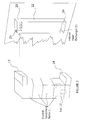
- Figure 1 is an external view of a sealed housing 1.
- the housing has a sealed door (not shown) to provide access to the equipment.
- a pair of exterior heat exchanger elements 2 are affixed to a wall of the housing 1.
- the heat exchangers include cooling fins or ribs 4.
- the fins are enclosed by a cowling arrangement.
- a fan 3 may also be provided to blow air through the cowling to remove heat from the fins.
- Figure 2 shows a partly exploded view of a plurality of equipment racks enclosed in cowlings to form a column of ducted equipment racks 11 through which air can be circulated by Fans 12.
- Extensions 13 and 14 of the equipment ducting are arranged to interface with an interior heat exchanger element 21 having a plurality of fins or ribs 25 enclosed in ducting 22 and having openings 23 and 24 to interface with the ducting extensions 13 and 14 respectively.
- the equipment in each equipment rack may include a plurality of circuit boards arranged in spaced apart parallel vertical planes.
- the air from the fans can pass over the surface of the circuit boards to remove heat from the circuit boards.
- the heated air then passes through extension 13 to interior heat exchanger 21 via vent 23 where the heat is transferred to the Fins 25.
- the air is then circulated back to the intake of the Fans 12 via opening 24 and extension 14.
- the interior heat exchanger element 21 is aligned with a corresponding exterior heat exchanger element 2 shown in Figure 1. Thus the heat from Fins 25 of the interior heat exchanger is transferred to the fins 4 of the exterior heat exchanger 4 by conduction through the walls of the housing 1.
- the fins 4 may be cooled by natural connection.
- the fins 4 are enclosed in a cowling 6, and cooled by Fan 3.
- an acoustic baffle 10, Figure 3 is fitted to the output vent 7 of the exterior heat exchanger.
- the direction of the output 8 from the fan 3 is preferably directed transverse to the output 9 from vent 7 to reduce the noise radiated in the direction 9.
- the thermostat 30 located in the equipment housing preferably in the equipment ducting, is used to switch off the exterior fan 3 when the equipment temperature is below a predetermined threshold.
- This condition will generally prevail at nighttime as the solar heating load of about 1200w/m2 is removed ( ⁇ 1600 w total).
- the equipment is each column may, for example, generate 300w, so the demands on the system are lessened, and unforced convection may be adequate to cool the exterior part of the heat exchanger. With the exterior fan turned off, the equipment can satisfy the stricter nighttime noise limit.
- the equipment cowling has a much smaller unsupported span than the inner shell of the prior art, there is less secondary noise generated by reverberation.
- Another advantage of the present invention is that the air between the outer housing and the equipment cowling is static because the outer housing is not vented. This static air forms a thermal insulator to partially isolate the equipment from the solar heating effect.
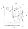
- the roof of the cabinet serves as the top of the equipment ducting.
- the air blown over the equipment is then blown against the roof of the cabinet. This air is at the highest temperature as it has just been blown over the equipment.
- the roof is designed as a double layer with an air cavity between the upper and lower levels. The cavity is vented to the atmosphere.
- the air from the external heat exchanger section is ducted into the roof cavity. Effectively, the inner roof layer becomes a part of the heat exchanger.
- the top of the equipment ducting is formed by part of the inner roof layer indicated at 43.
- the outer heat exchanger ducting is connected to the outer roof layer instead of being vented to the atmosphere. This makes the cavity between the inner and outer roof layers effectively part of the outer heat exchanger cooling air path 41.
- fan 3 forces air over the external heat exchanger fins and this air is then forced into the roof cavity and vented through venting slots 44.
- One or more transverse baffles 45 may depend from the outer layer into the cavity to cause the flow to be biased towards the inner layer.
- the fans 12, 13 are placed above the equipment racks so their output is directed against the region 40 of the inner roof layer.
- the turbulence created by the forced air discharge against region 43 may facilitate the transfer of heat from the air to the inner layer in the inner heat exchange air flow circuit 42.
- the outer heat exchange air flow path 41 extracts heat from the outer exchanger fins so the hottest air leaves the top of the exchanger fins and then passes over the region 43.
Landscapes
- Engineering & Computer Science (AREA)
- Power Engineering (AREA)
- Aviation & Aerospace Engineering (AREA)
- Physics & Mathematics (AREA)
- Thermal Sciences (AREA)
- Microelectronics & Electronic Packaging (AREA)
- Cooling Or The Like Of Electrical Apparatus (AREA)
- Patch Boards (AREA)
Applications Claiming Priority (4)
| Application Number | Priority Date | Filing Date | Title |
|---|---|---|---|
| AUPP749899 | 1999-06-16 | ||
| AUPP749899 | 1999-06-16 | ||
| AU3531400 | 2000-05-08 | ||
| AU35314/00A AU766013B2 (en) | 1999-06-16 | 2000-05-08 | Ducted cooling equipment housing |
Publications (3)
| Publication Number | Publication Date |
|---|---|
| EP1061788A2 true EP1061788A2 (de) | 2000-12-20 |
| EP1061788A3 EP1061788A3 (de) | 2001-09-12 |
| EP1061788B1 EP1061788B1 (de) | 2004-01-28 |
Family
ID=25623216
Family Applications (1)
| Application Number | Title | Priority Date | Filing Date |
|---|---|---|---|
| EP20000440165 Expired - Lifetime EP1061788B1 (de) | 1999-06-16 | 2000-05-30 | Gehäuse einer Anlage mit Kühlluftführung |
Country Status (3)
| Country | Link |
|---|---|
| EP (1) | EP1061788B1 (de) |
| DE (1) | DE60007924T2 (de) |
| ES (1) | ES2213559T3 (de) |
Cited By (5)
| Publication number | Priority date | Publication date | Assignee | Title |
|---|---|---|---|---|
| AU767843B2 (en) * | 2000-11-28 | 2003-11-27 | Samsung Electronics Co., Ltd. | System and method for temperature management in an electronic enclosure |
| GB2411050A (en) * | 2004-02-16 | 2005-08-17 | E2V Tech Uk Ltd | Electrical apparatus cooling system |
| CN112652984A (zh) * | 2020-12-15 | 2021-04-13 | 新沂市五联电气科技有限公司 | 一种配电柜监测终端及配电柜 |
| CN112736735A (zh) * | 2021-01-12 | 2021-04-30 | 国网上海市电力公司 | 一种配电站智能散热方法及系统 |
| CN113423238A (zh) * | 2021-05-19 | 2021-09-21 | 中国五冶集团有限公司 | 一种建筑电气施工安全防护装置 |
Families Citing this family (1)
| Publication number | Priority date | Publication date | Assignee | Title |
|---|---|---|---|---|
| CN111740327A (zh) * | 2020-07-04 | 2020-10-02 | 华翔翔能科技股份有限公司 | 一种智能箱式变电站组网装置 |
Family Cites Families (6)
| Publication number | Priority date | Publication date | Assignee | Title |
|---|---|---|---|---|
| DE2231469A1 (de) * | 1972-06-27 | 1974-03-07 | Siemens Ag | Waermeaustauscher fuer einen elektronikschrank |
| DE2622470A1 (de) * | 1976-05-20 | 1977-12-08 | Bosch Gmbh Robert | Gehaeuse fuer eine elektronische steuerung mit waermeaustauscher |
| DE2744664C2 (de) * | 1977-10-04 | 1988-01-21 | Leopold 6831 Reilingen Weinlich | Staubdicht abgeschlossenes Gehäuse zur Aufnahme wärmeabgebender elektrischer Einrichtungen |
| DE2844672A1 (de) * | 1978-10-13 | 1980-04-24 | Georg Prof Seewang | Gehaeuse fuer elektronische geraete |
| DE3717540A1 (de) * | 1987-05-25 | 1988-12-15 | Autz & Herrmann Maschf | An einer wand oder tuer eines schaltschrankes anzuordnender waermetauscher |
| GB2277767B (en) * | 1993-05-06 | 1996-07-10 | Nokia Telecommunications Oy | Telecommunications base stations |
-
2000
- 2000-05-30 DE DE2000607924 patent/DE60007924T2/de not_active Expired - Lifetime
- 2000-05-30 ES ES00440165T patent/ES2213559T3/es not_active Expired - Lifetime
- 2000-05-30 EP EP20000440165 patent/EP1061788B1/de not_active Expired - Lifetime
Cited By (7)
| Publication number | Priority date | Publication date | Assignee | Title |
|---|---|---|---|---|
| AU767843B2 (en) * | 2000-11-28 | 2003-11-27 | Samsung Electronics Co., Ltd. | System and method for temperature management in an electronic enclosure |
| GB2411050A (en) * | 2004-02-16 | 2005-08-17 | E2V Tech Uk Ltd | Electrical apparatus cooling system |
| US7729115B2 (en) | 2004-02-16 | 2010-06-01 | E2V Technologies (Uk) Limited | Electrical apparatus and cooling system |
| CN112652984A (zh) * | 2020-12-15 | 2021-04-13 | 新沂市五联电气科技有限公司 | 一种配电柜监测终端及配电柜 |
| CN112652984B (zh) * | 2020-12-15 | 2021-12-31 | 新沂市五联电气科技有限公司 | 一种具有配电柜监测终端的配电柜 |
| CN112736735A (zh) * | 2021-01-12 | 2021-04-30 | 国网上海市电力公司 | 一种配电站智能散热方法及系统 |
| CN113423238A (zh) * | 2021-05-19 | 2021-09-21 | 中国五冶集团有限公司 | 一种建筑电气施工安全防护装置 |
Also Published As
| Publication number | Publication date |
|---|---|
| EP1061788A3 (de) | 2001-09-12 |
| ES2213559T3 (es) | 2004-09-01 |
| DE60007924D1 (de) | 2004-03-04 |
| EP1061788B1 (de) | 2004-01-28 |
| DE60007924T2 (de) | 2004-07-29 |
Similar Documents
| Publication | Publication Date | Title |
|---|---|---|
| US5040095A (en) | Thermally controlled equipment cabinet | |
| CN1074962C (zh) | 焊接电源壳体 | |
| EP0103412B1 (de) | Steuergerät für Umsetzer und dergleichen | |
| JP3348552B2 (ja) | 電子機器の冷却装置 | |
| KR20000000118U (ko) | 통신장비 함체용 방열 및 발열 장치 | |
| US20090296321A1 (en) | Electrical cabinet with two cooling channels | |
| US6504714B1 (en) | Multi-level thermal management system and method | |
| CN208061081U (zh) | 一种防尘计算机机箱 | |
| CN215582079U (zh) | 散热机箱 | |
| JP2001267774A (ja) | 機器収納用筐体 | |
| EP1061788B1 (de) | Gehäuse einer Anlage mit Kühlluftführung | |
| CN220287613U (zh) | 电控盒组件、室外机及空调器 | |
| CN217009984U (zh) | 一种具有散热除湿功能的控制柜 | |
| AU766013B2 (en) | Ducted cooling equipment housing | |
| JP2004044962A (ja) | 冷却装置 | |
| WO2002037919A1 (en) | Climate control of an outdoor cabinet | |
| AU626026B2 (en) | Cooling of electronic equipment cabinets | |
| CN216752636U (zh) | 一种高效散热的服务器机柜 | |
| US6075697A (en) | Use of pressurized enclosure for impingement cooling of electronic component | |
| CN114465100A (zh) | 一种防尘散热配电箱 | |
| JPH0590776A (ja) | プリント板ユニツト | |
| JP2008091606A (ja) | 電気電子機器収納用キャビネット | |
| CN224054546U (zh) | 一种高效散热电器盒及包含其的油烟机 | |
| KR200261557Y1 (ko) | 통신장비용 냉각장치 | |
| CN223168571U (zh) | 逆变器散热结构和逆变器 |
Legal Events
| Date | Code | Title | Description |
|---|---|---|---|
| PUAI | Public reference made under article 153(3) epc to a published international application that has entered the european phase |
Free format text: ORIGINAL CODE: 0009012 |
|
| AK | Designated contracting states |
Kind code of ref document: A2 Designated state(s): AT BE CH CY DE DK ES FI FR GB GR IE IT LI LU MC NL PT SE Kind code of ref document: A2 Designated state(s): DE ES FR GB IT |
|
| AX | Request for extension of the european patent |
Free format text: AL;LT;LV;MK;RO;SI |
|
| PUAL | Search report despatched |
Free format text: ORIGINAL CODE: 0009013 |
|
| AK | Designated contracting states |
Kind code of ref document: A3 Designated state(s): AT BE CH CY DE DK ES FI FR GB GR IE IT LI LU MC NL PT SE |
|
| AX | Request for extension of the european patent |
Free format text: AL;LT;LV;MK;RO;SI |
|
| RIC1 | Information provided on ipc code assigned before grant |
Free format text: 7H 05K 7/20 A, 7H 02B 1/56 B |
|
| 17P | Request for examination filed |
Effective date: 20011013 |
|
| AKX | Designation fees paid |
Free format text: DE ES FR GB IT |
|
| 17Q | First examination report despatched |
Effective date: 20021003 |
|
| GRAP | Despatch of communication of intention to grant a patent |
Free format text: ORIGINAL CODE: EPIDOSNIGR1 |
|
| GRAS | Grant fee paid |
Free format text: ORIGINAL CODE: EPIDOSNIGR3 |
|
| GRAA | (expected) grant |
Free format text: ORIGINAL CODE: 0009210 |
|
| AK | Designated contracting states |
Kind code of ref document: B1 Designated state(s): DE ES FR GB IT |
|
| REG | Reference to a national code |
Ref country code: GB Ref legal event code: FG4D |
|
| REF | Corresponds to: |
Ref document number: 60007924 Country of ref document: DE Date of ref document: 20040304 Kind code of ref document: P |
|
| REG | Reference to a national code |
Ref country code: ES Ref legal event code: FG2A Ref document number: 2213559 Country of ref document: ES Kind code of ref document: T3 |
|
| ET | Fr: translation filed | ||
| PLBE | No opposition filed within time limit |
Free format text: ORIGINAL CODE: 0009261 |
|
| STAA | Information on the status of an ep patent application or granted ep patent |
Free format text: STATUS: NO OPPOSITION FILED WITHIN TIME LIMIT |
|
| 26N | No opposition filed |
Effective date: 20041029 |
|
| REG | Reference to a national code |
Ref country code: GB Ref legal event code: 732E Free format text: REGISTERED BETWEEN 20131114 AND 20131120 |
|
| REG | Reference to a national code |
Ref country code: FR Ref legal event code: GC Effective date: 20140717 |
|
| REG | Reference to a national code |
Ref country code: FR Ref legal event code: RG Effective date: 20141016 |
|
| REG | Reference to a national code |
Ref country code: FR Ref legal event code: PLFP Year of fee payment: 16 |
|
| REG | Reference to a national code |
Ref country code: FR Ref legal event code: PLFP Year of fee payment: 17 |
|
| PGFP | Annual fee paid to national office [announced via postgrant information from national office to epo] |
Ref country code: DE Payment date: 20160520 Year of fee payment: 17 Ref country code: GB Payment date: 20160520 Year of fee payment: 17 Ref country code: ES Payment date: 20160512 Year of fee payment: 17 |
|
| PGFP | Annual fee paid to national office [announced via postgrant information from national office to epo] |
Ref country code: IT Payment date: 20160524 Year of fee payment: 17 Ref country code: FR Payment date: 20160520 Year of fee payment: 17 |
|
| REG | Reference to a national code |
Ref country code: DE Ref legal event code: R119 Ref document number: 60007924 Country of ref document: DE |
|
| GBPC | Gb: european patent ceased through non-payment of renewal fee |
Effective date: 20170530 |
|
| REG | Reference to a national code |
Ref country code: FR Ref legal event code: ST Effective date: 20180131 |
|
| PG25 | Lapsed in a contracting state [announced via postgrant information from national office to epo] |
Ref country code: GB Free format text: LAPSE BECAUSE OF NON-PAYMENT OF DUE FEES Effective date: 20170530 Ref country code: DE Free format text: LAPSE BECAUSE OF NON-PAYMENT OF DUE FEES Effective date: 20171201 |
|
| PG25 | Lapsed in a contracting state [announced via postgrant information from national office to epo] |
Ref country code: FR Free format text: LAPSE BECAUSE OF NON-PAYMENT OF DUE FEES Effective date: 20170531 Ref country code: IT Free format text: LAPSE BECAUSE OF NON-PAYMENT OF DUE FEES Effective date: 20170530 |
|
| REG | Reference to a national code |
Ref country code: ES Ref legal event code: FD2A Effective date: 20180704 |
|
| PG25 | Lapsed in a contracting state [announced via postgrant information from national office to epo] |
Ref country code: ES Free format text: LAPSE BECAUSE OF NON-PAYMENT OF DUE FEES Effective date: 20170531 |