EP1061984B1 - Dispositif de respiration tracheale - Google Patents
Dispositif de respiration tracheale Download PDFInfo
- Publication number
- EP1061984B1 EP1061984B1 EP99939165A EP99939165A EP1061984B1 EP 1061984 B1 EP1061984 B1 EP 1061984B1 EP 99939165 A EP99939165 A EP 99939165A EP 99939165 A EP99939165 A EP 99939165A EP 1061984 B1 EP1061984 B1 EP 1061984B1
- Authority
- EP
- European Patent Office
- Prior art keywords
- fold
- tracheal
- ventilating device
- cuff
- balloon
- Prior art date
- Legal status (The legal status is an assumption and is not a legal conclusion. Google has not performed a legal analysis and makes no representation as to the accuracy of the status listed.)
- Expired - Lifetime
Links
- 230000029058 respiratory gaseous exchange Effects 0.000 title abstract 2
- 210000003437 trachea Anatomy 0.000 claims abstract description 51
- 230000028327 secretion Effects 0.000 claims abstract description 45
- 239000000463 material Substances 0.000 claims abstract description 25
- 239000011888 foil Substances 0.000 claims abstract description 13
- 210000004704 glottis Anatomy 0.000 claims abstract description 10
- 229920001684 low density polyethylene Polymers 0.000 claims description 6
- 239000004702 low-density polyethylene Substances 0.000 claims description 6
- 210000004877 mucosa Anatomy 0.000 claims description 3
- -1 polyethylene Polymers 0.000 claims description 3
- 239000004814 polyurethane Substances 0.000 claims description 3
- 239000004800 polyvinyl chloride Substances 0.000 claims description 3
- 239000000314 lubricant Substances 0.000 claims 2
- 239000004698 Polyethylene Substances 0.000 claims 1
- 229920000573 polyethylene Polymers 0.000 claims 1
- 208000015181 infectious disease Diseases 0.000 abstract description 3
- 230000000241 respiratory effect Effects 0.000 abstract description 2
- 238000009423 ventilation Methods 0.000 description 30
- 210000000867 larynx Anatomy 0.000 description 15
- 210000003238 esophagus Anatomy 0.000 description 9
- 230000002496 gastric effect Effects 0.000 description 9
- 238000007789 sealing Methods 0.000 description 9
- 239000007788 liquid Substances 0.000 description 8
- 210000001260 vocal cord Anatomy 0.000 description 8
- 230000015572 biosynthetic process Effects 0.000 description 7
- 210000003800 pharynx Anatomy 0.000 description 6
- 210000001519 tissue Anatomy 0.000 description 6
- 206010035664 Pneumonia Diseases 0.000 description 5
- 230000007774 longterm Effects 0.000 description 5
- 210000004072 lung Anatomy 0.000 description 5
- 210000004400 mucous membrane Anatomy 0.000 description 5
- 238000002627 tracheal intubation Methods 0.000 description 5
- 238000004026 adhesive bonding Methods 0.000 description 4
- 238000013461 design Methods 0.000 description 4
- 230000007246 mechanism Effects 0.000 description 4
- 244000052769 pathogen Species 0.000 description 4
- 230000001717 pathogenic effect Effects 0.000 description 4
- 229920000139 polyethylene terephthalate Polymers 0.000 description 4
- 239000005020 polyethylene terephthalate Substances 0.000 description 4
- 230000002792 vascular Effects 0.000 description 4
- 238000003466 welding Methods 0.000 description 4
- 230000037303 wrinkles Effects 0.000 description 4
- 239000000853 adhesive Substances 0.000 description 3
- 210000003484 anatomy Anatomy 0.000 description 3
- 210000003685 cricoid cartilage Anatomy 0.000 description 3
- 239000012530 fluid Substances 0.000 description 3
- 239000000523 sample Substances 0.000 description 3
- 208000032843 Hemorrhage Diseases 0.000 description 2
- 230000001070 adhesive effect Effects 0.000 description 2
- 230000000903 blocking effect Effects 0.000 description 2
- 210000002409 epiglottis Anatomy 0.000 description 2
- 230000005764 inhibitory process Effects 0.000 description 2
- MJIHNNLFOKEZEW-UHFFFAOYSA-N lansoprazole Chemical compound CC1=C(OCC(F)(F)F)C=CN=C1CS(=O)C1=NC2=CC=CC=C2N1 MJIHNNLFOKEZEW-UHFFFAOYSA-N 0.000 description 2
- 230000003902 lesion Effects 0.000 description 2
- 230000010412 perfusion Effects 0.000 description 2
- 238000003825 pressing Methods 0.000 description 2
- 238000012549 training Methods 0.000 description 2
- 208000012287 Prolapse Diseases 0.000 description 1
- 238000009825 accumulation Methods 0.000 description 1
- 239000012790 adhesive layer Substances 0.000 description 1
- 230000002411 adverse Effects 0.000 description 1
- 230000003444 anaesthetic effect Effects 0.000 description 1
- 238000004873 anchoring Methods 0.000 description 1
- 244000052616 bacterial pathogen Species 0.000 description 1
- 238000001266 bandaging Methods 0.000 description 1
- 230000008901 benefit Effects 0.000 description 1
- 230000000740 bleeding effect Effects 0.000 description 1
- 230000036772 blood pressure Effects 0.000 description 1
- 230000036770 blood supply Effects 0.000 description 1
- 230000008859 change Effects 0.000 description 1
- 239000003795 chemical substances by application Substances 0.000 description 1
- 230000001055 chewing effect Effects 0.000 description 1
- 238000010276 construction Methods 0.000 description 1
- 230000007123 defense Effects 0.000 description 1
- 230000008260 defense mechanism Effects 0.000 description 1
- 230000001419 dependent effect Effects 0.000 description 1
- 238000011161 development Methods 0.000 description 1
- 238000006073 displacement reaction Methods 0.000 description 1
- 230000000694 effects Effects 0.000 description 1
- 210000000981 epithelium Anatomy 0.000 description 1
- 230000005284 excitation Effects 0.000 description 1
- 239000004744 fabric Substances 0.000 description 1
- 238000001727 in vivo Methods 0.000 description 1
- 230000002757 inflammatory effect Effects 0.000 description 1
- 230000002401 inhibitory effect Effects 0.000 description 1
- 230000001788 irregular Effects 0.000 description 1
- 238000012423 maintenance Methods 0.000 description 1
- 230000035699 permeability Effects 0.000 description 1
- 229920000915 polyvinyl chloride Polymers 0.000 description 1
- 230000002265 prevention Effects 0.000 description 1
- 238000012545 processing Methods 0.000 description 1
- 230000009467 reduction Effects 0.000 description 1
- 230000001105 regulatory effect Effects 0.000 description 1
- 230000000630 rising effect Effects 0.000 description 1
- 230000006641 stabilisation Effects 0.000 description 1
- 238000011105 stabilization Methods 0.000 description 1
- 230000000087 stabilizing effect Effects 0.000 description 1
- 229910052623 talc Inorganic materials 0.000 description 1
- 235000012222 talc Nutrition 0.000 description 1
- 239000000454 talc Substances 0.000 description 1
- 230000000472 traumatic effect Effects 0.000 description 1
- 210000005239 tubule Anatomy 0.000 description 1
- 238000011144 upstream manufacturing Methods 0.000 description 1
- XLYOFNOQVPJJNP-UHFFFAOYSA-N water Substances O XLYOFNOQVPJJNP-UHFFFAOYSA-N 0.000 description 1
- 230000037373 wrinkle formation Effects 0.000 description 1
Images




Classifications
-
- A—HUMAN NECESSITIES
- A61—MEDICAL OR VETERINARY SCIENCE; HYGIENE
- A61M—DEVICES FOR INTRODUCING MEDIA INTO, OR ONTO, THE BODY; DEVICES FOR TRANSDUCING BODY MEDIA OR FOR TAKING MEDIA FROM THE BODY; DEVICES FOR PRODUCING OR ENDING SLEEP OR STUPOR
- A61M16/00—Devices for influencing the respiratory system of patients by gas treatment, e.g. ventilators; Tracheal tubes
- A61M16/04—Tracheal tubes
-
- A—HUMAN NECESSITIES
- A61—MEDICAL OR VETERINARY SCIENCE; HYGIENE
- A61M—DEVICES FOR INTRODUCING MEDIA INTO, OR ONTO, THE BODY; DEVICES FOR TRANSDUCING BODY MEDIA OR FOR TAKING MEDIA FROM THE BODY; DEVICES FOR PRODUCING OR ENDING SLEEP OR STUPOR
- A61M16/00—Devices for influencing the respiratory system of patients by gas treatment, e.g. ventilators; Tracheal tubes
- A61M16/04—Tracheal tubes
- A61M16/0402—Special features for tracheal tubes not otherwise provided for
- A61M16/042—Special features for tracheal tubes not otherwise provided for with separate conduits for in-and expiration gas, e.g. for limited dead volume
-
- A—HUMAN NECESSITIES
- A61—MEDICAL OR VETERINARY SCIENCE; HYGIENE
- A61M—DEVICES FOR INTRODUCING MEDIA INTO, OR ONTO, THE BODY; DEVICES FOR TRANSDUCING BODY MEDIA OR FOR TAKING MEDIA FROM THE BODY; DEVICES FOR PRODUCING OR ENDING SLEEP OR STUPOR
- A61M16/00—Devices for influencing the respiratory system of patients by gas treatment, e.g. ventilators; Tracheal tubes
- A61M16/04—Tracheal tubes
- A61M16/0434—Cuffs
- A61M16/0436—Special fillings therefor
- A61M16/0438—Liquid-filled
-
- A—HUMAN NECESSITIES
- A61—MEDICAL OR VETERINARY SCIENCE; HYGIENE
- A61M—DEVICES FOR INTRODUCING MEDIA INTO, OR ONTO, THE BODY; DEVICES FOR TRANSDUCING BODY MEDIA OR FOR TAKING MEDIA FROM THE BODY; DEVICES FOR PRODUCING OR ENDING SLEEP OR STUPOR
- A61M16/00—Devices for influencing the respiratory system of patients by gas treatment, e.g. ventilators; Tracheal tubes
- A61M16/04—Tracheal tubes
- A61M16/0434—Cuffs
- A61M16/0443—Special cuff-wall materials
-
- A—HUMAN NECESSITIES
- A61—MEDICAL OR VETERINARY SCIENCE; HYGIENE
- A61M—DEVICES FOR INTRODUCING MEDIA INTO, OR ONTO, THE BODY; DEVICES FOR TRANSDUCING BODY MEDIA OR FOR TAKING MEDIA FROM THE BODY; DEVICES FOR PRODUCING OR ENDING SLEEP OR STUPOR
- A61M16/00—Devices for influencing the respiratory system of patients by gas treatment, e.g. ventilators; Tracheal tubes
- A61M16/04—Tracheal tubes
- A61M16/0434—Cuffs
- A61M16/0445—Special cuff forms, e.g. undulated
-
- A—HUMAN NECESSITIES
- A61—MEDICAL OR VETERINARY SCIENCE; HYGIENE
- A61M—DEVICES FOR INTRODUCING MEDIA INTO, OR ONTO, THE BODY; DEVICES FOR TRANSDUCING BODY MEDIA OR FOR TAKING MEDIA FROM THE BODY; DEVICES FOR PRODUCING OR ENDING SLEEP OR STUPOR
- A61M16/00—Devices for influencing the respiratory system of patients by gas treatment, e.g. ventilators; Tracheal tubes
- A61M16/04—Tracheal tubes
- A61M16/0434—Cuffs
- A61M16/0454—Redundant cuffs
- A61M16/0456—Redundant cuffs one cuff within another
-
- A—HUMAN NECESSITIES
- A61—MEDICAL OR VETERINARY SCIENCE; HYGIENE
- A61M—DEVICES FOR INTRODUCING MEDIA INTO, OR ONTO, THE BODY; DEVICES FOR TRANSDUCING BODY MEDIA OR FOR TAKING MEDIA FROM THE BODY; DEVICES FOR PRODUCING OR ENDING SLEEP OR STUPOR
- A61M16/00—Devices for influencing the respiratory system of patients by gas treatment, e.g. ventilators; Tracheal tubes
- A61M16/04—Tracheal tubes
- A61M16/0434—Cuffs
- A61M16/0454—Redundant cuffs
- A61M16/0459—Redundant cuffs one cuff behind another
-
- A—HUMAN NECESSITIES
- A61—MEDICAL OR VETERINARY SCIENCE; HYGIENE
- A61M—DEVICES FOR INTRODUCING MEDIA INTO, OR ONTO, THE BODY; DEVICES FOR TRANSDUCING BODY MEDIA OR FOR TAKING MEDIA FROM THE BODY; DEVICES FOR PRODUCING OR ENDING SLEEP OR STUPOR
- A61M16/00—Devices for influencing the respiratory system of patients by gas treatment, e.g. ventilators; Tracheal tubes
- A61M16/04—Tracheal tubes
- A61M16/0402—Special features for tracheal tubes not otherwise provided for
- A61M16/0415—Special features for tracheal tubes not otherwise provided for with access means to the stomach
Definitions
- the invention relates to a tracheal ventilation device, in particular Tracheal tube or tracheal cannula that connects the trachea to a patient's ventilation closed as tightly as possible, with one blocking the trachea below the glottis Cuff bladder through which a ventilation cannula is passed, the cuff bladder in the filled, freely unfoldable state is larger than in the filled Condition placed in the trachea, and consists of flexible soft film material, , the cuff bladder can be applied to the trachea by drapery.
- a tracheal ventilation device in particular Tracheal tube or tracheal cannula that connects the trachea to a patient's ventilation closed as tightly as possible, with one blocking the trachea below the glottis Cuff bladder through which a ventilation cannula is passed, the cuff bladder in the filled, freely unfoldable state is larger than in the filled Condition placed in the trachea, and consists of flexible soft film material, , the
- a tracheal ventilator proposed in US-A-3,766,927 Genus has a cuff bladder, which is larger than the trachea and from the inside applying pressure to the trachea.
- the foil material of the cuff bladder has a thickness of 0.0254 mm, alternatively a thickness of 0.0762 mm is also proposed becomes.
- US-A-3 610 247 discloses a tracheal ventilator, which is of the Structure corresponds to the device disclosed in US-A-3,766,927.
- she has a cuff bladder made of preferably semi-permeable material, which at its Can deliver an anesthetic to the wall of the trachea.
- Wall thicknesses of the film are given as examples of 0.05, 0.07 and 0.1 mm theoretically, films thinner than 0.05 mm can also be used.
- Regarding the Seal shows this device a behavior similar to US-A-3,766,927.
- the cuff bladder expands when inflated it is elastic and lies close to the wall without folds the trachea. If the filling pressure of the cuff bladder exceeds the blood pressure of the Mucous membrane supplying the vascular bed, so serious structural Lesions of the epithelium may result. Especially in long-term incubated patients should the filling pressure in the cuff bladder at the lowest possible, the mucosal perfusion non-impairing level. However, the filling pressure chosen too low, this can lead to leakage of bacterially populated pharynx the cuff bladder and thus for colonization and infection of the lung tissue to lead.
- the invention has for its object a tracheal ventilation device to improve the genre mentioned in such a way that a patient with it can be intubated for as long as possible at low pressures, the risk of infection should be low.
- a generic Tracheal ventilation device which is characterized in that the Wall thickness of the film is less than or equal to 0.02 mm and the cuff bubble is designed such that the fold eyelet that arises at the dead end of a fold has a small diameter that allows the free flow of the secretion through counteracts the wrinkle eyelet.
- the flow of secretions can be controlled by the specific training of Influence cuff folding in the area of a fold eyelet, i.e. on the fold base. While it was previously assumed in the prior art that cuff bubbles with drapery because of the low filling pressure not sufficiently close to the Trachea may be present, the invention provides a way to inhibit the Secretion flow in the area of a fold eyelet. Form when blocking the cuff at the deep end of the fold, at the base of the fold, fold eyelets, which one such have a small diameter that the flow of secretion is slowed down or ideally comes to a standstill. This can already be the case with film thicknesses from or below 0.002 mm enter.
- the eyelet is preferably formed in a capillary size. Adequate results then result Adhesive forces of the secretion on the fold eyelet or a sufficient viscosity-dependent resistance of the secretion to reduce the flow of secretion.
- the flow velocity in the capillary-sized fold eyelet is then less than the theoretically possible speed without adhesion or viscosity forces, so that less secretion flows through over time.
- the diameter the eyelet should be designed so small that the flow of secretion comes to a complete standstill.
- the diameter of the fold eyelet can be particularly advantageously less than 0.11 or 0.05 mm. Below 0.1 mm there is already a certain inhibition of the Secretion flow rate through the eyelet. With a wrinkle eye diameter of less than 0.05 mm the secretion flow slows down and comes close to to a halt.
- the wall thickness of the film material can advantageously be chosen to be so thin that that the inner radius of the fold eyelets that form is physiologically acceptable Filling pressure reduced to such an extent that secretions are prevented from flowing freely becomes.
- the wall thicknesses of conventional cuff bubbles are mostly in the range of 0.06 up to 0.1 mm.
- the wall thickness of the film is approximately 0.01 to 0.005 mm.
- a wall thickness of 0.01 to 0.005 mm you can use a soft, flexible Already a satisfactory inhibition of the secretion flow or its stasis in the Area of the fold base can be reached.
- the film material can be the cuff bladder for example made of polyethylene terephthalate (PETP), low-density polyethylene (LDPE), Polyvinyl chloride (PCV) or polyurethane (PU) exist. These materials are compatible with the body and are particularly suitable in thin-walled processing good for forming a tightly fitting drapery. Copolymer mecanicischept to modify the material properties are conceivable (e.g. LDPE-EVA).
- PETP polyethylene terephthalate
- LDPE low-density polyethylene
- PCV Polyvinyl chloride
- PU polyurethane
- the cuff bladder may be made of a self-adhesive material its adhesion to reduce the clear diameter of an eyelet on the base of the folds contributes.
- the wall thickness of the film can be in the area of the folds be thinner than in the wrinkle-free area immediately adjacent to the tracheal mucosa Area. Wrinkles preferably form in the thin-walled cuff area, because the film is easier to deform here.
- the fold base can be due to the lesser Form wall thickness of eyelets of smaller diameter. In the thick-walled cuff area the cuff coat behaves somewhat more rigidly between the folds, so that it is only rounded lies against the wall of the trachea.
- the fold walls lying opposite one another can be connected to each other in the area near the base of the folds.
- the liaison office can be provided immediately adjacent to the forming eyelet be so that through them the size of the fold eyelet to a desired Diameter is to be set.
- the opposite fold walls at the dead end of the Fold, filling the eyelet be connected to each other and thus the flow of secretion is safe prevention.
- the opposing fold walls of a fold with one another are conceivable be welded or glued.
- variable fold section in which the opposite fold walls are not physically connected.
- the cuff bladder of the trachea the concept, can fold with a variable depth of fold Adjust residual cuff coat, in size and shape.
- the tamponler bladder is recommended also to be designed with residual volume, i.e. their volume with free development should exceed the volume of the inner larynx to be filled.
- the Tampon bladder corresponds to the sealing principles according to the invention and gentle cuff bladder design. The formation of the described capillary This prevents structures.
- the invention proposes the addition of an additional mechanical cuff to the cuff sealing, the previously described design principles for sealing and Tissue bladder corresponding to tissue compatibility.
- the tampon bladder can be pressurized with a minimum filling pressure of preferably 10 to 15 mbar, which is only the task of unfolding the thin, sealing bladder wall Has.
- the tampon bladder can be arranged and related to the tube shaft or for fixing cuff the embodiments described in DE 196 38 935 correspond.
- the fixing cuff on the caudal side of the Device, and the tampon bladder is mounted cranially relative thereto.
- the tampon bladder can expand in the direction of the subglottic space and provides a seal there, upstream of the fixing cuff against secretions seeping in from the throat.
- the fixation cuff and the tampon bladder can be used sequentially Be positioned on the ventilator cannula arrangement.
- the tampon bladder can In terms of its extent, the so-called subglottic space is partially covered up to to the glottic level or slightly beyond. Since both bubbles have corresponding Supply lumens attached separately within the tube shaft The functions of the fixing cuff and tampon bladder can be filled controlled largely independently of each other in a serial arrangement become.
- connection point between the two is preferably arranged in series Bubbles designed so that in their area, in the filled, tracheally unfolded Condition, no secretions can accumulate.
- the fixing cuff can advantageously, at least in regions, preferably completely enclosed by the tampon bladder.
- the outer tampon can therefore extend caudally into a variable area of the fixing cuff expand. The formation of a pathogen reservoir between the This prevents bubbles.
- the cuff is tracheally fixing the tube completely enclosed by the tampon bladder.
- the tampon blister ranges from the chewing data End over the cranial end of the cuff up to the so-called subglottic Space into or up to or slightly above the area of the vocal fold level out.
- the combination of one fixing cuff with a tampon bladder the invention proposes a special Type of handling before.
- the outer, fluid-tight closing should initially Tamponing bladder are filled and the wall of the inner space to be filled nestle under minimal pressure. Then the inside Arranged cuff to stabilize the tube in the trachea in the usual way Unfolded and with usual inflation pressures. The fixation cuff has therefore no liquid contact, the possible formation of fold eyelets in the coat the inner cuff has no liquid draining effect.
- the stasis contains material containing excitation above the tracheally fixing cuff practically completely prevented, can be chronically inflammatory Changes in the mucous membrane can also be prevented.
- the tampon bladder extends beyond the vocal folds into the supraglottic Area, the permanent traumatic contact of the tube shaft with the Vocal cords through the tension-free covering of the vocal cords with the coat the tampon bladder can be reduced.
- Tracheostomy tubes are not placed over the larynx, but inserted into the trachea through an operative opening (stoma).
- a printed figure or a specific shape of the reservoir bladder can be selected, which changes with the corresponding Fill state changed in a specific way.
- the supply leg leading to the tampon bladder should be sufficiently large can be selected in order to be able to quickly equalize the pressure.
- Any suitable fluid can be used to fill the sealing or fixing cuff bubbles be used.
- a valve mechanism can also be dispensed with when using liquid Celts and the filling can be regulated solely via an open liquid column.
- the seal according to the invention of the tracheal or tracheal or laryngeal residual lumen by reducing the wall thickness of the cuff to within the liquid-tight tamponade also makes up the area of a few micrometers intubated newborn, infant and toddler trachea conceivable.
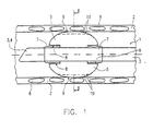
- FIG. 1 shows a first embodiment of a tracheal tube 1 according to the invention or a tracheal ventilation device, which is placed in a trachea 2 is.
- a hollow ventilation cannula 3 ends at its caudal end 4 at an oblique angle their longitudinal axis. At the caudal end 4, ventilation air enters the lungs and out.
- the ventilation cannula 3 leads in a manner not shown over the larynx and the throat out of the patient's mouth and is there with suitable Respirators (not shown) connected.
- a cuff bladder 5 is attached to the ventilation cannula 3 near the caudal end 4.
- the ventilation cannula extends through the cuff bladder.
- the tube 1 is inserted into the trachea 2 such that the cuff 5 in the middle Trachea comes to rest.
- the trachea are suggestively ring-shaped Tracheal clips 6 shown.
- the cuff bladder 5 is approximately balloon-shaped and surrounds the ventilation cannula 3 approximately tubular. It is at two spaced ends 7 attached to the ventilation cannula 3, e.g. by bandaging, shrinking, Welding or gluing, so that the fixed end 7 of the bladder 5 is fluid-tight on the Cannula 3 rests.
- the cannula 3 is connected to a fluid via a connection (not shown in FIG. 1) desired pressure can be filled.
- a fold 8 is provided on the bladder, which extends in a ring around the ventilation cannula 3. With the help of the envelope fold 8 are sufficient axial movements of the cuff bladder 5 and the ventilation cannula 3 relative to each other possible without the contact surface of the cuff bladder 5 medically adversely affected on the trachea 2.
- the cuff bladder 5 is shown placed in the trachea when filled.
- the filling pressure is approximately 20 to 30 mbar (preferably 25 mbar).
- the residual cuff coat folds into folds which are directed predominantly radially inward 10.
- the material of the cuff bladder 5 consists of a flexible soft foil material, preferably with a wall thickness of less than 0.02mm, optimally however 0.01 to 0.005 mm.
- the film material is compatible with the body and exists eg. Made of polyethylene terephthalate (PETP), low-density polyethylene (LDPE), polyvinyl chloride (PVC) or polyurethane (PU).
- the film is not or only minimally stretched, but flexibly curved. It lies with folds 10 of the trachea 2 on.
- the fold areas are indicated by dashed lines.
- the folds are 10 typically arranged axially to the trachea 2 and the ventilation cannula 3 mostly along, parallel to the tube shaft 3
- the wall thickness of the Film is preferably thinner in the area of the formation of the folds 10 than in the wrinkle-free area Area of the contact surface 9.
- the selected filling pressure of the cuff bladder can be between 10 and 30 mbar lie.
- FIG. 2 shows a cross-sectional view along the section line II-II in FIG. 1, with respect to parts of the same reference numerals, reference is made to the description of FIG. 1 becomes.
- Figure 2 it can be seen how the cuff bladder is filled 5, protruding approximately radially inwards, form the folds 10. The folding results from the diameter of the cuff bladder 5, which is larger than in the freely unfolded state the cross section of the trachea 2 to be filled in.
- Each of the folds 10 has at its end, the fold base 11, a fold eyelet 12, which is characterized by the envelope of the cuff in this area.
- FIGS. 3 and 4 depict the enlarged representations of the folds 10.
- Regarding the same reference numerals can be referred to the existing description of the figures.
- each fold 10 consists of two opposing ones in parallel Folded walls 13 which are in physical contact with one another or by one thin secretion film are separated.
- the secretion film forms a certain adhesive layer between the two fold walls 13.
- the fold bridge is typical aligned radially inward from the contact surface 9 of the bladder.
- cuff bubbles of conventional wall thickness forms a fold eyelet 12 on the base of the fold, which forms liquid-guiding capillaries, forms with the application of the thinnest foils for cuff bladder construction a fold envelope 12 made of so small in diameter is that the free flow of the secretion at the base of the fold is inhibited or completely prevented becomes.
- the diameter of the fold eyelet is preferably less than 0.1 or 0.05 mm.
- the fold walls 13 lying opposite one another in the case of a fold 10 Area of the fold base directly by welding or gluing together connected.
- the eyelet 12 is the cause of a possible leak avoided by secretions.
- the fold section adjoining this connection area 16 17 is formed from opposing fold walls 13. This are not connected and form the variable fold section, the fold depth 15 adjusts to the respective tracheal diameter.
- the fold eyelet 12 can be formed in a capillary size at which the actual Flow rate of the secretion is lower than that through the free cross section the fold eyelet is theoretically possible without adhesion and viscosities Flow rate.
- the inhibitory effect of the adhesion and viscosity forces can be so pronounced with the appropriate size of the fold eyelet that the Fold eyelet 12 filled with secretions, but the flow of secretions is not possible is.
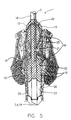
- FIG 5 is a second embodiment of an Enclotrachealtube 1 with the topographical Relationships to the relevant adjacent anatomical structures (Larynx and upper trachea).
- the tracheal tube passes from cranial 18 after caudal 19 the epiglottis (epiglottis) 20, the vocal folds (glottis) 21, and the adjoining the vocal folds so-called subglottic space 22, which is limited by the upper edge of the cuff 23.
- the mechanical anchoring of the tracheal tube occurs below the cricoid cartilage 6, but preferably in the area of the middle trachea by an air-blocked cuff 23.
- the cuff is located within a tampon bladder 24, the tampon bladder and cuff have separate lumens that are independent of each other can be filled.
- the cuff 23 and tampon bladder 24 lie close together when filled.
- the tampon remote bladder 24 extends to the subglottic space 22, up to glottis level 21 or slightly further up to the supraglottic Area 25.
- the cuff 23 does not necessarily have to be arranged inside the tampon bladder 24 his. It can also be in sequential order (cranially) on the tube be arranged, but advantageously in the filled state in the immediate, should be denser so that there is no space between the bubbles Can form a reservoir for germs. For this purpose the bubbles can be shared Contact area permanently connected.
- the two bubbles in the common support surface 26 in one variable distal section (e.g. distal third or distal half) with each other be glued or welded.
- a gluing or welding of the distal common bearing surface 26 is intended to prevent the thin-walled tampon bladder herniated caudally, or their debris in the event of a rupture of the tampon bladder turn caudally and at the caudal end 4 of the ventilation cannula Form the valve-like mechanism.
- the tampon bladder 24 is filled with a suitable liquid or gaseous fluid.
- FIG. 6 shows a third embodiment of a tracheal tube according to the invention displayed.
- the tracheal tube 1 is shown in the filled, freely unfolded state.
- the tampon bladder in the third embodiment 24 in the area of the later vocal fold placement with a preformed Incision 27 provided, which corresponds approximately to the anatomical structure of the glottis 21.
- the incision 27 is preferably not or only in the selected prints little stretch so that the glottis is not subjected to excessive pressure.
- a first channel 28 extends over a plurality of outlet openings 29 is connected to the tampon bladder 24.
- the channel 28 is in the Shaft of the tube integrated and extracorporeal with a scaled reservoir, with liquid Filling media, for example a water column 30, connected.
- the reservoir can however also be used as an expandable compensation balloon 31 (for liquid or gaseous Media).
- the volume of the equalization balloon should be at least correspond to the common volume of the tampon bladder and cuff.
- the material of the balancing balloon 31 is preferably easier to stretch than the material the tampon bladder 24. Pressure increases within the tampon bladder lead in this way preferably for an expansion of the compensation balloon, an expansion of the structures the larynx can be largely avoided.
- the outlet openings 29 are selected in size and number such that a rapid Volume shift between compensation balloon 31 and tampon bladder 24 possible is.
- the cuff 23 is via a second channel integrated in the tube shaft 32 connected to a filling balloon 33.
- the inflation balloon can be made according to the Lanz principle with a self-regulating valve mechanism or a simple one valve-carrying resrvoir bladder.
- FIGS. 7 and 8 show a special embodiment of the compensation balloon 31 shown.
- the compensation balloon 31 is not filled, so that a pattern 34 printed on its wall assumes an irregular deformation.
- the balloon is expanded so that the printed pattern 34 in a straight regular shape appears, which shows the optimal filling pressure the tampon bladder 24 displays.
- a corresponding change in shape of the compensating balloon could take place itself, from the unfilled to the filled state, to the correct one Filling pressure within the tampon bladder are closed.
- a compact, nested arrangement of the two is also conceivable Reservoir bladders for the supply of cuff and tampon bladder in one Version. While the inner bladder pressurized with higher filling pressure supplies the fixation cuff, the outer reservoir bladder holds the tampon bladder unfolded with moderate filling pressure.
- FIG. 9 shows the fourth embodiment of a tracheal ventilation device according to the invention a tracheostomy tube 35 is shown. It will not be natural Airways introduced, but via a so-called stoma 36, which is surgically the front side of the neck.
- the ventilation cannula 3 runs through the stoma 36 and kinks after entering the trachea 2 approximately at right angles to the caudal.
- the cuff bladder 5 is analog formed as in Figures 1 to 4, so that with respect to the same reference numerals reference is made to the previous explanations.
- the analog is Equalization balloon 31 with the channel 28 designed as described in relation to FIG. 6, so that reference is made to these statements in this regard.
- FIG. 10 shows a fifth embodiment of a tracheal ventilation device shown, which can be used as a tracheal tube 1 or as a tracheal cannula 35.
- This Embodiment corresponds to the embodiment shown in Figure 5. Same Parts are provided with the same reference numerals, so that in this regard the explanations refer to Figure 5.
- the tampon bladder is in the fifth embodiment in FIG 24 shorter and does not reach into the area of the glottis. In its expansion it corresponds approximately to the fixing cuff 23 For reasons of clarity, the two separate filling channels 28 and 29 are not located.
- the outer tampon bladder After inserting the cannula, the outer tampon bladder is primarily used as a seal filled. If additional mechanical stabilization of the tracheostomy tube is required, the inner fixing cuff is also unfolded. By contribution a separating agent between the cuff bubbles is the mutual mechanical Influencing the cuff 23 and tampon bladder 24 prevented. To ensure that the tracheal cannula is sealed, the tampon bladder is deployed via a communicating, extracorporeally attached reservoir maintain a mild filling pressure of preferably 10 to 15 mbar.
- FIG. 11 shows a section of a sixth embodiment of an inventive one Tracheal ventilation device shown. This embodiment is from developed the fifth embodiment according to Figure 10. The same parts are the same Provide reference numerals so that reference is made to the explanations relating to FIG can be.
- the fixating cuff 23 and the tampon bladder 24 are strictly sequential arranged one behind the other on the ventilation cannula 3.
- the bearing surface 26 of the cuff 23 and the tampon bladder 24 lie on its walls directly to each other so that no pathogen reservoir can form.
- the walls in the area of the support surface 26 can be connected to one another be glued or welded.
- the tracheal tube is inserted over the cricoid cartilage of the larynx during intubation advanced to the area of the upper tracheal braces so that the cuff bladder 5 comes to rest safely in the tracheal area.
- the shape of the cuff bladder is larger than when it is filled placed in the trachea. Placed in the trachea lies the cuff bladder 5 with a drape the contact surface 9 of the wall of the trachea.
- the cuff bladder 5 is designed such that there is a fold eyelet at the dead end of a fold 10 Forms 12 of such a small diameter that the flow of secretion is inhibited or comes to a complete standstill. This is preferably done by the viscosity of the Secretions or by the adhesive forces acting on the secretion within the capillary eye. The aspiration of secretions can be prevented and the emergence of a ventilation-associated pneumonia can be prevented.
- the small diameter of the eyelets 12 can be achieved by using certain achieved only a few micrometers thick, flexible foils in the cuff bubble design become.
- Variable areas of the opposing fold walls 13 can also be used e.g. be connected to each other by gluing or welding. Ideally such a connection of the fold walls 13 takes place in the area of the fold eyelet 12, so that every flow of secretion is prevented.
- the tracheal ventilation device can also be used as a gastric tube be used.
- the gastric tube is inserted into the esophagus instead of the trachea inserted, with a corresponding marking on the probe shaft is provided for positioning the probe.
- the esophagus Cuff bladder can be unfolded just as freely, with drapery on the wall of the The esophagus is tension-free and there are fold eyelets at the dead end of the resulting folds with such a small diameter that the free flow counteract secretions through the eyelets. This allows a gentle tamponing of the transmural tissue pressure Reach esophagus.
- the tissue of the esophagus is not under tension taken.
- the currently released lumen of the esophagus is being preserved the oesophageal fold is simply tamped.
- the gastric tube seals on long-term contracts Way against rising gastrointestinal secretion.
- gastric tubes and tracheal ventilation devices have always been separate Devices were constructed and not mutually for the other use were interchangeable. is both an application with the device according to the invention possible as a tracheal ventilation device or as a gastric tube.
- the Respiratory cannula is used in the case of the gastric tube as an inner channel-like lumen, through which an actual feeding tube can be carried out or through which the food supply itself takes place.
- the gastric tube can also be used in the sense of a so-called Senstaken Blakemore tube be used.
- the cuff bladder is also in the esophagus placed. This makes it possible to improve the blood supply to the surrounding vessels of the esophagus by varying the filling pressure of the cuff bladder. For example bleeding from surrounding mucosal vessels can be stopped. Training the specific, previously described unfolding of the residual Cuff jacket, it also allows the cuff filling to the necessary vascular closure pressure to adapt exactly without the cuff and adjoining To take structures under significant tension. Vascular hemorrhage can also occur with minimum necessary pressure can be prevented. The mucous membrane of the esophagus becomes like this as traumatized as possible. When used as a Sengstake, the interior serves channel-like lumens as a probe shaft. The gastric end of the tube can be open or closed.
Landscapes
- Health & Medical Sciences (AREA)
- Pulmonology (AREA)
- Life Sciences & Earth Sciences (AREA)
- Animal Behavior & Ethology (AREA)
- Anesthesiology (AREA)
- Biomedical Technology (AREA)
- Heart & Thoracic Surgery (AREA)
- Hematology (AREA)
- Emergency Medicine (AREA)
- Engineering & Computer Science (AREA)
- General Health & Medical Sciences (AREA)
- Public Health (AREA)
- Veterinary Medicine (AREA)
- Prostheses (AREA)
- Media Introduction/Drainage Providing Device (AREA)
- Respiratory Apparatuses And Protective Means (AREA)
- Absorbent Articles And Supports Therefor (AREA)
Abstract
Claims (25)
- Dispositif de respiration trachéale (1, 35), en particulier tube trachéal ou canule trachéale, qui obture le plus hermétiquement possible la trachée (2) pour la respiration d'un patient, comprenant un ballonnet (5) qui bloque la trachée (2) au-dessous de la glotte (21) et au travers duquel est guidée une canule respiratoire (3), le ballonnet (5) étant plus gros à l'état de remplissage, librement dépliable sans limite, que placé dans la trachée (2) à l'état de remplissage, et se composant de matériau en feuille souple flexible, le ballonnet (5) pouvant être appliqué par un plissage (10) sur la trachée (2), caractérisé en ce que l'épaisseur de paroi de la feuille est inférieure ou égale à 0,02 mm et le ballonnet a une réalisation telle que la boucle de pli (12), formée sur le bout (11) d'un pli (10), présente un faible diamètre qui contrecarre avec un effet de freinage le passage libre de la sécrétion au travers de la boucle (12).
- Dispositif de respiration trachéale (1, 35) suivant la revendication 1, caractérisé en ce que la boucle de pli (12) est réalisée en dimension capillaire, avec laquelle la vitesse d'écoulement effective de la sécrétion est plus faible que la vitesse d'écoulement théoriquement possible sans forces d'adhésion-viscosité au travers de la section transversale libre.
- Dispositif de respiration trachéale (1, 35) suivant l'une des revendications 1 et 2, caractérisé en ce que le diamètre de la boucle de pli (12) est inférieur à 0,1 ou 0,05 mm.
- Dispositif de respiration trachéale (1, 35) suivant l'une des revendications précédentes, caractérisé en ce que l'épaisseur de paroi du matériau en feuille est choisie avec une minceur telle que le passage de la sécrétion au travers de la boucle de pli (12) est freiné par rapport à un passage théoriquement libre.
- Dispositif de respiration trachéale (1, 35) suivant l'une des revendications précédentes, caractérisé en ce que l'épaisseur de paroi de la feuille est d'environ 0,01 à 0,005 mm.
- Dispositif de respiration trachéale (1, 35) suivant l'une des revendications précédentes, caractérisé en ce que l'épaisseur de paroi de la feuille est inférieure à 0,005 mm.
- Dispositif de respiration trachéale (1, 35) suivant l'une des revendications précédentes, caractérisé en ce que le matériau en feuille du ballonnet (5) se compose de polyéthylène téraphtalate (PETP), de polyéthylène basse densité (LDPE), de chlorure de polyvinyle (PVC) ou de polyuréthanne (PU).
- Dispositif de respiration trachéale (1, 35) suivant l'une des revendications précédentes, caractérisé en ce que l'épaisseur de paroi de la feuille dans la zone du plissage (10) est plus mince que dans la zone (9) sans plis s'appliquant directement sur la muqueuse de la trachée.
- Dispositif de respiration trachéale (1, 35) suivant l'une des revendications précédentes, caractérisé en ce que les parois de plis (13), en vis-à-vis dans un pli (10), sont assemblées entre elles dans la zone proche du fond de pli (11).
- Dispositif de respiration trachéale (1, 35) suivant la revendication 9, caractérisé en ce que les parois de plis (13) en vis-à-vis sont assemblées entre elles sur le bout (11) du pli (10) directement dans le fond de pli (11) en remplissant la boucle de pli (12).
- Dispositif de respiration trachéale (1, 35) suivant l'une des revendications 9 et 10, caractérisé en ce que les parois en vis-à-vis (13) d'un pli (10) sont soudées ou collées entre elles.
- Dispositif de respiration trachéale (1, 35) suivant l'une des revendications 9 à 11, caractérisé en ce que dans le pli (10), une section de pli (17) de section transversale variable dans la profondeur de pli (15) se raccorde de façon limitrophe à la zone d'assemblage (16) des parois de plis en vis-à-vis (13), section dans laquelle les parois de plis en vis-à-vis (13) ne sont pas assemblées entre elles par alliance de matière.
- Dispositif de respiration trachéale (1, 35) suivant l'une des revendications précédentes, caractérisé en ce que le ballonnet (5) se compose d'un matériau facilement adhérent en lui-même sur le plissage (10).
- Dispositif de respiration trachéale (1, 35) suivant l'une des revendications précédentes, caractérisé en ce qu'il est prévu sur la canule respiratoire (3) un ballonnet de tamponnade (24) réalisé sous forme de ballonnet trachéal et une manchette de fixation (23) séparée, positionnable au-dessous de la glotte (21).
- Dispositif de respiration trachéale (1, 35) suivant la revendication 14, caractérisé en ce que la manchette de fixation (23) est prévue sur le côté caudal du dispositif et le ballonnet de tamponnade (24) sur le côté cranial par rapport à ce dernier.
- Dispositif de respiration trachéale (1, 35) suivant l'une des revendications 14 et 15, caractérisé en ce que la manchette de fixation (23) et le ballonnet de tamponnade (24) sont disposés à peu près de façon séquentielle l'un derrière l'autre le long de la canule respiratoire (3).
- Dispositif de respiration trachéale (1, 35) suivant l'une des revendications 14 à 16, caractérisé en ce que la manchette de fixation (23) s'applique à l'état de remplissage directement sur le ballonnet de tamponnade (24) sur une surface d'appui commune (26).
- Dispositif de respiration trachéale (1, 35) suivant l'une des revendications 14 à 17, caractérisé en ce que la manchette de fixation (23) est entourée au moins par zones, de préférence totalement, par le ballonnet de tamponnade (24).
- Dispositif de respiration trachéale (1, 35) suivant l'une des revendications 14 à 18, caractérisé en ce qu'un lubrifiant est prévu entre la manchette de fixation (23) et le ballonnet de tamponnade (24).
- Dispositif de respiration trachéale (1, 35) suivant la revendication 19, caractérisé en ce que le lubrifiant est prévu sur la surface d'appui (26) commune à l'état de remplissage du ballonnet de tamponnade (24) et de la manchette de fixation (23).
- Dispositif de respiration trachéale (1, 35) suivant l'une des revendications 14 à 20, caractérisé en ce que le ballonnet de tamponnade (24) et la manchette de fixation (23) peuvent être remplis indépendamment l'un de l'autre.
- Dispositif de respiration trachéale (1, 35) suivant l'une des revendications 14 à 21, caractérisé en ce que le ballonnet de tamponnade (24) est réalisé dans sa dimension à l'état de remplissage pour remplir l'espace sub-glottique (22).
- Dispositif de respiration trachéale (1, 35) suivant l'une des revendications 14 à 22, caractérisé en ce que le ballonnet de tamponnade (24) a une réalisation telle qu'il remplit aussi bien l'espace sub-glottique (22) que l'espace supra-glottique (25).
- Dispositif de respiration trachéale (1, 35) suivant l'une des revendications 14 à 23, caractérisé en ce que la configuration du ballonnet de tamponnade (24) à l'état de remplissage est différente de celle de la manchette (23).
- Dispositif de respiration trachéale (1, 35) suivant l'une des revendications 14 à 23, caractérisé en ce que l'épaisseur de feuille de la manchette de fixation (23) est supérieure à celle du ballonnet de tamponnade (24).
Priority Applications (1)
| Application Number | Priority Date | Filing Date | Title |
|---|---|---|---|
| EP04006726A EP1428544A3 (fr) | 1998-03-09 | 1999-02-23 | Dispositif de respiration trachéale |
Applications Claiming Priority (7)
| Application Number | Priority Date | Filing Date | Title |
|---|---|---|---|
| DE29804142U | 1998-03-09 | ||
| DE29804142U DE29804142U1 (de) | 1998-03-09 | 1998-03-09 | Trachealtubus |
| DE19826547 | 1998-06-15 | ||
| DE19826547 | 1998-06-15 | ||
| DE19845415A DE19845415B4 (de) | 1998-03-09 | 1998-10-02 | Trachealbeatmungsvorrichtung |
| DE19845415 | 1998-10-02 | ||
| PCT/EP1999/001175 WO1999045991A1 (fr) | 1998-03-09 | 1999-02-23 | Dispositif de respiration tracheale |
Related Child Applications (2)
| Application Number | Title | Priority Date | Filing Date |
|---|---|---|---|
| EP04006726A Division EP1428544A3 (fr) | 1998-03-09 | 1999-02-23 | Dispositif de respiration trachéale |
| EP04006726.6 Division-Into | 2004-03-19 |
Publications (3)
| Publication Number | Publication Date |
|---|---|
| EP1061984A1 EP1061984A1 (fr) | 2000-12-27 |
| EP1061984B1 true EP1061984B1 (fr) | 2004-06-02 |
| EP1061984B2 EP1061984B2 (fr) | 2010-03-03 |
Family
ID=27218450
Family Applications (1)
| Application Number | Title | Priority Date | Filing Date |
|---|---|---|---|
| EP99939165A Expired - Lifetime EP1061984B2 (fr) | 1998-03-09 | 1999-02-23 | Dispositif de respiration tracheale |
Country Status (7)
| Country | Link |
|---|---|
| US (2) | US6526977B1 (fr) |
| EP (1) | EP1061984B2 (fr) |
| JP (1) | JP3540745B2 (fr) |
| AU (1) | AU748342B2 (fr) |
| CA (1) | CA2322460C (fr) |
| ES (1) | ES2221415T5 (fr) |
| WO (1) | WO1999045991A1 (fr) |
Cited By (2)
| Publication number | Priority date | Publication date | Assignee | Title |
|---|---|---|---|---|
| US7654264B2 (en) | 2006-07-18 | 2010-02-02 | Nellcor Puritan Bennett Llc | Medical tube including an inflatable cuff having a notched collar |
| WO2017085540A1 (fr) | 2015-11-18 | 2017-05-26 | Creative Balloons Gmbh | Dispositif pour l'occlusion étanche dynamique ou le tamponnement par comblement d'un organe creux |
Families Citing this family (119)
| Publication number | Priority date | Publication date | Assignee | Title |
|---|---|---|---|---|
| US6526977B1 (en) * | 1998-03-09 | 2003-03-04 | Goebel Fred G. | Tracheal breathing apparatus |
| SE0003420L (sv) * | 2000-09-25 | 2002-04-16 | Bjoern Flodin | Anordning för fixering av ett rörorgan |
| US7204252B2 (en) * | 2001-12-21 | 2007-04-17 | Eidon, Llc | Surface energy assisted fluid transport system |
| US20050166926A1 (en) * | 2002-01-21 | 2005-08-04 | Hiroaki Nomori | Tracheostomy tube |
| US7040312B2 (en) | 2002-05-16 | 2006-05-09 | Engineered Medical Systems, Inc. | Perilaryngeal oral airway with flexible tip guide |
| GB0218868D0 (en) | 2002-08-14 | 2002-09-25 | Nasir Muhammed A | Improved airway management device |
| SE0203590D0 (sv) * | 2002-12-04 | 2002-12-04 | Siemens Elema Ab | Medicinsk anordning |
| US20040220534A1 (en) * | 2003-04-29 | 2004-11-04 | Martens Paul W. | Medical device with antimicrobial layer |
| DE10321990B4 (de) * | 2003-05-15 | 2005-10-13 | Microcuff Gmbh | Trachealbeatmungungsvorrichtung |
| US7806119B2 (en) * | 2003-08-14 | 2010-10-05 | Intersurgical Uab | Airway device |
| US7013899B2 (en) | 2004-08-13 | 2006-03-21 | Engineered Medical System, Inc. | Perilaryngeal oral airway with multi-lumen esophogeal-obturator |
| US7811235B2 (en) * | 2004-10-13 | 2010-10-12 | Massachusetts Eye & Ear Infirmary | Aerodynamic tissue driver |
| JP2008520290A (ja) * | 2004-11-19 | 2008-06-19 | サターン バイオメディカル システムズ インコーポレイテッド | 分泌物を除去する換気用カテーテルおよび気道確保システム |
| US20090211572A1 (en) * | 2004-11-19 | 2009-08-27 | Matera Paul A | Endotracheal intubation apparatus providing enhanced stability in an intubated patient |
| EP1861152B1 (fr) * | 2005-02-28 | 2018-09-12 | Tracoe medical GmbH | Dispositif d'amenee d'air respiratoire |
| US20060278235A1 (en) * | 2005-06-14 | 2006-12-14 | White Steven C | Tracheal tube with above the cuff drainage |
| US20070106320A1 (en) * | 2005-11-10 | 2007-05-10 | John Blix | Balloon catheter for distal protection compatability |
| US20070289596A1 (en) * | 2006-06-14 | 2007-12-20 | Campbell Shannon E | Endotracheal cuff and technique for using the same |
| US20070296125A1 (en) * | 2006-06-22 | 2007-12-27 | Joel Colburn | Thin cuff for use with medical tubing and method and apparatus for making the same |
| US20070295337A1 (en) * | 2006-06-22 | 2007-12-27 | Nelson Donald S | Endotracheal cuff and technique for using the same |
| US8196584B2 (en) | 2006-06-22 | 2012-06-12 | Nellcor Puritan Bennett Llc | Endotracheal cuff and technique for using the same |
| US8434487B2 (en) * | 2006-06-22 | 2013-05-07 | Covidien Lp | Endotracheal cuff and technique for using the same |
| US20080053454A1 (en) * | 2006-09-01 | 2008-03-06 | Nellcor Puritan Bennett Incorporated | Endotracheal tube including a partially inverted cuff collar |
| DE102006044740A1 (de) * | 2006-09-20 | 2008-04-03 | Tracoe Medical Gmbh | Manschette einer Beatmungsvorrichtung |
| US8684175B2 (en) | 2006-09-22 | 2014-04-01 | Covidien Lp | Method for shipping and protecting an endotracheal tube with an inflated cuff |
| US8561614B2 (en) * | 2006-09-28 | 2013-10-22 | Covidien Lp | Multi-layer cuffs for medical devices |
| US8307830B2 (en) * | 2006-09-29 | 2012-11-13 | Nellcor Puritan Bennett Llc | Endotracheal cuff and technique for using the same |
| US8807136B2 (en) * | 2006-09-29 | 2014-08-19 | Covidien Lp | Self-sizing adjustable endotracheal tube |
| US20080078405A1 (en) * | 2006-09-29 | 2008-04-03 | Crumback Gary L | Self-sizing adjustable endotracheal tube |
| US20080078399A1 (en) * | 2006-09-29 | 2008-04-03 | O'neil Michael P | Self-sizing adjustable endotracheal tube |
| US7950393B2 (en) * | 2006-09-29 | 2011-05-31 | Nellcor Puritan Bennett Llc | Endotracheal cuff and technique for using the same |
| US20080078401A1 (en) * | 2006-09-29 | 2008-04-03 | Nellcor Puritan Bennett Incorporated | Self-sizing adjustable endotracheal tube |
| US20080140106A1 (en) * | 2006-12-12 | 2008-06-12 | Kimberly-Clark Worldwide, Inc. | Enhanced cuff sealing for endotracheal tubes |
| US20080215034A1 (en) * | 2007-03-02 | 2008-09-04 | Jessica Clayton | Endotracheal cuff and technique for using the same |
| US20080210243A1 (en) * | 2007-03-02 | 2008-09-04 | Jessica Clayton | Endotracheal cuff and technique for using the same |
| US20080262428A1 (en) * | 2007-04-18 | 2008-10-23 | Kimberly-Clark Worldwide, Inc. | Method for vap preventative ventilation of intubated critically ill patients |
| WO2008132745A2 (fr) * | 2007-04-30 | 2008-11-06 | Spatz Fgia, Inc. | Insertion et retrait d'un dispositif sans endoscope |
| US20090014009A1 (en) * | 2007-07-13 | 2009-01-15 | Kimberly-Clark Worldwide, Inc. | Toroidal endotracheal cuffs for ventilator associated pneumonia reduction |
| US20090032027A1 (en) * | 2007-07-30 | 2009-02-05 | Mccachren Brian Christopher | Multiple balloon endotracheal tube cuff |
| US8313687B2 (en) | 2007-09-20 | 2012-11-20 | Kimberly-Clark Worldwide, Inc. | Method of making an improved balloon cuff tracheostomy tube |
| US8607795B2 (en) * | 2007-09-20 | 2013-12-17 | Kimberly-Clark Worldwide, Inc. | Balloon cuff tracheostomy tube |
| US20090090365A1 (en) * | 2007-09-20 | 2009-04-09 | Cuevas Brian J | Balloon cuff tracheostomy tube with greater ease of insertion |
| US20090209908A1 (en) * | 2007-09-20 | 2009-08-20 | Cuevas Brian J | Tubular workpiece for producing an improved balloon cuff tracheostomy tube |
| US20090120439A1 (en) * | 2007-11-08 | 2009-05-14 | Fred Goebel | Method of triggering a ventilator |
| US20090159085A1 (en) * | 2007-12-21 | 2009-06-25 | Kimberly-Clark Worldwide, Inc. | Piezoelectric polymer cuff for use in an artificial airway |
| US8750978B2 (en) * | 2007-12-31 | 2014-06-10 | Covidien Lp | System and sensor for early detection of shock or perfusion failure and technique for using the same |
| US20090281532A1 (en) * | 2008-05-07 | 2009-11-12 | The General Hospital Corporation | Arrangement for use with a balloon ablation catheter |
| GB0810169D0 (en) * | 2008-06-04 | 2008-07-09 | Cosmeplast Ets | Improvements relating to respiratory interface devices |
| US20090320853A1 (en) * | 2008-06-27 | 2009-12-31 | Mike Kenowski | Tracheostomy Tube |
| US20090320834A1 (en) * | 2008-06-27 | 2009-12-31 | Cuevas Brian J | Dilator Loading Catheter |
| US20100051035A1 (en) * | 2008-08-29 | 2010-03-04 | Jenkins Shawn E | Low-pressure airway management device with active coating and method for patient care |
| US20100147309A1 (en) | 2008-12-12 | 2010-06-17 | Cuevas Brian J | Tracheal Catheter With a Flexible Lumen for Subglottic Suctioning |
| US8381730B2 (en) * | 2009-01-29 | 2013-02-26 | Covidien Lp | Medical device and technique for using the same |
| US20100186211A1 (en) * | 2009-01-29 | 2010-07-29 | Nellcor Puritan Bennett Llc | Medical device and technique for using the same |
| US20100300448A1 (en) * | 2009-05-28 | 2010-12-02 | Kenowski Michael A | Tracheostomy Tube |
| US20100300449A1 (en) * | 2009-05-28 | 2010-12-02 | Chan Sam C | Position Indicator for Tracheostomy Tube |
| US8590534B2 (en) * | 2009-06-22 | 2013-11-26 | Covidien Lp | Cuff for use with medical tubing and method and apparatus for making the same |
| USD665495S1 (en) | 2009-07-14 | 2012-08-14 | Muhammed Aslam Nasir | Medical device |
| US9119926B2 (en) | 2009-07-31 | 2015-09-01 | Avent, Inc. | Subglottic suctioning system |
| US8795360B2 (en) | 2009-10-22 | 2014-08-05 | Kimberly-Clark Worldwide, Inc. | Cam action detachment for tracheostomy tube |
| DE102009053067A1 (de) * | 2009-11-13 | 2011-05-19 | Willy Rüsch GmbH | Trachealtubus mit Temperatursensor |
| US9539081B2 (en) | 2009-12-02 | 2017-01-10 | Surefire Medical, Inc. | Method of operating a microvalve protection device |
| US8434486B2 (en) * | 2009-12-18 | 2013-05-07 | Covidien Lp | Supraglottic fixation device for endotracheal tubes |
| US8535265B2 (en) * | 2009-12-22 | 2013-09-17 | Kimberly-Clark Worldwide, Inc. | Tracheal catheter with suction lumen port in close proximity to the cuff |
| GB201010647D0 (en) | 2010-06-24 | 2010-08-11 | Docsinnovent Ltd | Stopper device |
| US20120017897A1 (en) | 2010-07-20 | 2012-01-26 | Sridhar Ranganathan | Tracheal Tube Cuff Pressure Indicator |
| US20120017913A1 (en) | 2010-07-26 | 2012-01-26 | Schumacher James F | Tracheostomy Tube Loading Catheter |
| WO2012092104A1 (fr) | 2010-12-30 | 2012-07-05 | Ticona Llc | Poudre contenant un polymère de polyoxyméthylène pour revêtir des substrats métalliques |
| USD693920S1 (en) | 2011-06-08 | 2013-11-19 | Intersurgical Ag | Airway device |
| USD688787S1 (en) | 2011-06-08 | 2013-08-27 | Intersurgical Ag | Airway device cap and strap holder |
| USD665254S1 (en) | 2011-06-08 | 2012-08-14 | Intersurgical Ag | Airway device packaging |
| USD712244S1 (en) | 2011-09-23 | 2014-09-02 | Intersurgical Ag | Medical device package |
| US9821130B2 (en) | 2011-12-08 | 2017-11-21 | Avent, Inc. | Multi-diameter pediatric tracheal cuff |
| WO2013090619A1 (fr) | 2011-12-15 | 2013-06-20 | The Board Of Trustees Of The Leland Stanford Junior University | Dispositifs et méthodes pour prévenir l'aspiration trachéale |
| GB201201438D0 (en) | 2012-01-27 | 2012-03-14 | Docsinnovent Ltd | Improved stopper device |
| USD761952S1 (en) | 2012-07-27 | 2016-07-19 | Docsinnovent Limited | Airway device |
| US9131988B2 (en) | 2012-09-28 | 2015-09-15 | Avent, Inc. | Self positioning tracheal tube clearance mechanism using skives |
| EP4464374A3 (fr) | 2012-11-02 | 2025-01-15 | Neurotronic, Inc. | Formulations d'ablation chimique pour diverses maladies |
| US12208224B2 (en) | 2012-11-02 | 2025-01-28 | Neurotronic, Inc. | Chemical ablation and method of treatment for various diseases |
| US9204963B2 (en) | 2013-03-13 | 2015-12-08 | Gyrus Acmi, Inc. | Stabilizing implant with expandable segments |
| CA2930662A1 (fr) | 2013-11-15 | 2015-05-21 | Ciel Medical, Inc. | Dispositifs et procedes destines a l'aspiration des voies aeriennes |
| GB2555360B (en) | 2013-12-17 | 2018-10-10 | Intersurgical Ag | Intubating Airway Device |
| US9968740B2 (en) | 2014-03-25 | 2018-05-15 | Surefire Medical, Inc. | Closed tip dynamic microvalve protection device |
| GB201416891D0 (en) | 2014-09-25 | 2014-11-12 | Smiths Medical Int Ltd | Tracheal Tubes And Seals |
| GB201419141D0 (en) | 2014-10-28 | 2014-12-10 | Smiths Medical Int Ltd | Tracheal tubes and cuffs |
| EP3212274A4 (fr) * | 2014-10-30 | 2018-06-27 | Neurotronic, Inc. | Ablation chimique et méthodes destinées à traiter diverses maladies |
| US20220080141A1 (en) * | 2014-12-04 | 2022-03-17 | Creative Balloons Gmbh | Device and method for the dynamically sealing occlusion or space-filling tamponade of a hollow organ |
| EP3226949B1 (fr) * | 2014-12-04 | 2019-08-21 | Creative Balloons GmbH | Dispositif permettant de réaliser l'occlusion d'un organe creux en assurant une étanchéité dynamique ou le tamponnement d'un tel organe par remplissage d'espace |
| US20160287839A1 (en) | 2015-03-31 | 2016-10-06 | Surefire Medical, Inc. | Apparatus and Method for Infusing an Immunotherapy Agent to a Solid Tumor for Treatment |
| USD1051359S1 (en) | 2015-06-15 | 2024-11-12 | Intersurgical Ag | Airway device |
| USD842456S1 (en) | 2015-12-15 | 2019-03-05 | Intersurgical Ag | Airway device |
| AU2015406930B2 (en) | 2015-08-27 | 2020-09-10 | Avent, Inc. | Variable flow rate control device |
| US10105519B2 (en) * | 2015-10-20 | 2018-10-23 | C.R. Bard, Inc. | Variable diameter medical balloon |
| US11191662B2 (en) | 2015-11-06 | 2021-12-07 | Avent, Inc. | Ostomy device, apparatus, and system |
| JP2017093611A (ja) * | 2015-11-19 | 2017-06-01 | テルモ株式会社 | カフ及び気管チューブ |
| CN108738314B (zh) * | 2016-03-30 | 2020-11-10 | 国立大学法人神户大学 | 倾斜膨胀式球囊导管和球囊用基座 |
| WO2017176881A1 (fr) | 2016-04-05 | 2017-10-12 | University Of Maryland, Baltimore | Procédé et appareil pour une gastrostomie à ultrasons de coaptation |
| JP2018538113A (ja) * | 2016-05-17 | 2018-12-27 | アスピセーフ ソリューションズ インコーポレイテッド | 拡張型挿管組立体 |
| US10780250B1 (en) | 2016-09-19 | 2020-09-22 | Surefire Medical, Inc. | System and method for selective pressure-controlled therapeutic delivery |
| US11400263B1 (en) | 2016-09-19 | 2022-08-02 | Trisalus Life Sciences, Inc. | System and method for selective pressure-controlled therapeutic delivery |
| WO2018085035A1 (fr) * | 2016-11-01 | 2018-05-11 | Michael Carney | Dispositif respiratoire |
| US10588636B2 (en) | 2017-03-20 | 2020-03-17 | Surefire Medical, Inc. | Dynamic reconfigurable microvalve protection device |
| US10179219B2 (en) | 2017-04-13 | 2019-01-15 | Daniel Marcos Chapiro | Intubation device with variable backflow pressure |
| JP6275317B2 (ja) * | 2017-09-08 | 2018-02-07 | 国立大学法人神戸大学 | バルーン用土台及び斜め膨張型バルーンカテーテル |
| DE102017010422A1 (de) | 2017-11-11 | 2019-05-16 | Creative Balloons Gmbh | Ballon mit mehrlagigem Wandungsaufbau für die dynamische Dichtung von Organen und Hohlräumen im Körper |
| US10173022B1 (en) | 2017-11-29 | 2019-01-08 | Airway Medix S.A. | Laryngeal mask cuff |
| US10744287B2 (en) | 2017-11-29 | 2020-08-18 | Airway Medix S.A. | Laryngeal mask cuffs |
| GB201720733D0 (en) | 2017-12-13 | 2018-01-24 | Ashkal Development Ltd | Airway device |
| US20190314591A1 (en) * | 2018-04-17 | 2019-10-17 | John Allen Pacey | Secretion clearing endotracheal tube (scet) |
| US20210275766A1 (en) * | 2018-06-01 | 2021-09-09 | Coaptech Llc | Systems, apparatus, and methods for performing a percutaneous tracheostomy |
| US11850398B2 (en) | 2018-08-01 | 2023-12-26 | Trisalus Life Sciences, Inc. | Systems and methods for pressure-facilitated therapeutic agent delivery |
| DE102018121001A1 (de) | 2018-08-28 | 2020-03-05 | Tracoe Medical Gmbh | Beatmungsvorrichtung |
| US20220118205A1 (en) * | 2018-09-25 | 2022-04-21 | Airway Medix S.A. | Ventilation tubes with inflatable cuffs |
| US11338117B2 (en) | 2018-10-08 | 2022-05-24 | Trisalus Life Sciences, Inc. | Implantable dual pathway therapeutic agent delivery port |
| JP1649724S (fr) | 2019-01-18 | 2020-01-14 | ||
| US12433597B2 (en) | 2019-06-04 | 2025-10-07 | Trisalus Life Sciences, Inc. | Atraumatic occlusive system with compartment for measurement of vascular pressure change |
| US20220233819A1 (en) * | 2019-06-10 | 2022-07-28 | The Regents Of The University Of Michigan | Repositionable medical tube with ultrasonically-detectable cuff |
| EP4034208B1 (fr) * | 2019-09-24 | 2025-08-13 | Advanced Medical Balloons GmbH | Conduite d'alimentation à flux optimisé vers un élément de type ballonnet à étanchéification dynamique, synchrone d'un organe |
| USD1025348S1 (en) | 2020-04-16 | 2024-04-30 | Intersurgical Ag | Airway device |
Family Cites Families (43)
| Publication number | Priority date | Publication date | Assignee | Title |
|---|---|---|---|---|
| GB1171439A (en) | 1967-04-10 | 1969-11-19 | Jorge Alberto Millet Puig | Improvements in an Endotracheal Tube |
| US3565079A (en) | 1968-04-09 | 1971-02-23 | Richard Robert Jackson | Self-inflating endotracheal tube |
| US3669098A (en) | 1968-10-05 | 1972-06-13 | Olympus Optical Co | Endotracheal tube |
| US3610247A (en) * | 1969-03-03 | 1971-10-05 | Richard R Jackson | Surface-anesthetizing medical appliance |
| US3638655A (en) * | 1970-05-18 | 1972-02-01 | George O Doherty | Intubation tubes |
| US3640282A (en) | 1970-08-06 | 1972-02-08 | Jack M Kamen | Tracheal tube with normally expanded balloon cuff |
| GB1402255A (en) | 1971-09-24 | 1975-08-06 | Smiths Industries Ltd | Medical or surgical devices of the kind having an inflatable balloon |
| US3766927A (en) | 1971-10-22 | 1973-10-23 | R Jackson | Hydraulic cuff tracheal tube |
| US3818515A (en) | 1972-11-13 | 1974-06-25 | W Neville | Bifurcated tracheo-bronchial prostheses |
| US3848605A (en) | 1973-04-23 | 1974-11-19 | American Hospital Supply Corp | Endotracheal tube with improved inflation retention means |
| US3901246A (en) | 1974-01-24 | 1975-08-26 | Airco Inc | Balloon tracheal catheter with inflation valve and indicator |
| US4018231A (en) | 1974-01-24 | 1977-04-19 | Airco, Inc. | Disposable balloon type catheter |
| US4156428A (en) | 1974-08-26 | 1979-05-29 | Henkin Melvyn Lane | Tracheal tube with expandable cuff system |
| US3948273A (en) * | 1974-09-13 | 1976-04-06 | Medical Engineering Corporation | Endotracheal tube having a non-sticking inner surface |
| US3964488A (en) | 1974-11-13 | 1976-06-22 | Wallace H. Ring | Tracheal tube |
| US4020849A (en) | 1975-12-01 | 1977-05-03 | Jackson Richard R | Cuff inflation for tracheal tubes |
| US4091816A (en) * | 1977-01-28 | 1978-05-30 | Elam James O | Double cuffed endotracheal tube |
| US4141364A (en) * | 1977-03-18 | 1979-02-27 | Jorge Schultze | Expandable endotracheal or urethral tube |
| US4235239A (en) | 1978-09-15 | 1980-11-25 | Elam James O | Cuffed endotrachael tube and method |
| US4423725A (en) | 1982-03-31 | 1984-01-03 | Baran Ostap E | Multiple surgical cuff |
| EP0274411A3 (fr) † | 1987-01-09 | 1988-11-30 | C.R. Bard, Inc. | Ballon de haute résistance à paroi mince et son procédé de fabrication |
| US4820349A (en) † | 1987-08-21 | 1989-04-11 | C. R. Bard, Inc. | Dilatation catheter with collapsible outer diameter |
| US5049131A (en) * | 1989-05-31 | 1991-09-17 | Ashridge Ag | Balloon catheter |
| DE3921524A1 (de) * | 1989-06-30 | 1991-01-10 | Ruesch Willy Ag | Trachealtubus mit permeationsstabiler blockungsmanschette |
| US5263485A (en) | 1989-09-18 | 1993-11-23 | The Research Foundation Of State University Of New York | Combination esophageal catheter for the measurement of atrial pressure |
| US5038777A (en) * | 1991-03-14 | 1991-08-13 | Dunn Margarette T | Endotracheal device |
| DE4115497A1 (de) | 1991-05-11 | 1992-11-12 | Ruesch Willy Ag | Trachealtubus mit permeationsstabiler blockungsmanschette |
| US5305740A (en) * | 1991-09-12 | 1994-04-26 | The United States Of America As Represented By The Secretary Of The Department Of Health And Human Services | Sealing means for endotracheal tubes |
| US5546936A (en) | 1992-05-19 | 1996-08-20 | Mallinckrodt Medical, Inc. | Tracheal tube with reinforced flexible segment |
| US5403280A (en) * | 1993-02-16 | 1995-04-04 | Wang; James C. | Inflatable perfusion catheter |
| US5322062A (en) * | 1993-04-08 | 1994-06-21 | Servas Francis M | Non-inflatable sealing cuff for tracheal tube and other cannula |
| US5469863A (en) † | 1993-08-11 | 1995-11-28 | Polygenex International, Inc. | Polyurethane condom of welded polyurethane film |
| JP3694524B2 (ja) * | 1993-08-23 | 2005-09-14 | ボストン サイエンティフィック コーポレイション | 改良形バルーンカテーテル |
| US5746745A (en) * | 1993-08-23 | 1998-05-05 | Boston Scientific Corporation | Balloon catheter |
| DE4334037A1 (de) | 1993-10-06 | 1995-04-13 | Ruesch Willy Ag | Balloninstrument für natürliche und/oder künstliche Körperhohlräume |
| US5520174A (en) | 1994-02-14 | 1996-05-28 | Evans; Larry L. | Tracheostomy tube guard |
| US5531905A (en) | 1994-12-02 | 1996-07-02 | Dober Chemical Corporation | System and method to control laundry waste water treatment |
| US5638813A (en) | 1995-06-07 | 1997-06-17 | Augustine Medical, Inc. | Tracheal tube with self-supporting tracheal tube cuff |
| US5653230A (en) | 1996-01-19 | 1997-08-05 | Cook Incorporated | Percutaneous balloon dilational tracheostomy tube |
| US5765559A (en) * | 1996-04-25 | 1998-06-16 | Higher Dimension Research, Inc. | Multi-cuffed endotracheal tube and method of its use |
| DE19654910C2 (de) † | 1996-09-10 | 2003-03-27 | Fred Goebel Patentverwaltung G | Magensonde |
| US5873362A (en) * | 1997-03-18 | 1999-02-23 | Parker Medical Limited Partnership | Endotracheal tube |
| US6526977B1 (en) * | 1998-03-09 | 2003-03-04 | Goebel Fred G. | Tracheal breathing apparatus |
-
1999
- 1999-02-23 US US09/446,845 patent/US6526977B1/en not_active Expired - Lifetime
- 1999-02-23 AU AU32539/99A patent/AU748342B2/en not_active Expired
- 1999-02-23 ES ES99939165T patent/ES2221415T5/es not_active Expired - Lifetime
- 1999-02-23 EP EP99939165A patent/EP1061984B2/fr not_active Expired - Lifetime
- 1999-02-23 WO PCT/EP1999/001175 patent/WO1999045991A1/fr not_active Ceased
- 1999-02-23 JP JP2000535402A patent/JP3540745B2/ja not_active Expired - Lifetime
- 1999-02-23 CA CA002322460A patent/CA2322460C/fr not_active Expired - Lifetime
-
2002
- 2002-11-15 US US10/294,560 patent/US6802317B2/en not_active Expired - Lifetime
Cited By (3)
| Publication number | Priority date | Publication date | Assignee | Title |
|---|---|---|---|---|
| US7654264B2 (en) | 2006-07-18 | 2010-02-02 | Nellcor Puritan Bennett Llc | Medical tube including an inflatable cuff having a notched collar |
| US8096299B2 (en) | 2006-07-18 | 2012-01-17 | Nellcor Puritan Bennett Llc | Medical tube including an inflatable cuff having a notched collar |
| WO2017085540A1 (fr) | 2015-11-18 | 2017-05-26 | Creative Balloons Gmbh | Dispositif pour l'occlusion étanche dynamique ou le tamponnement par comblement d'un organe creux |
Also Published As
| Publication number | Publication date |
|---|---|
| US6526977B1 (en) | 2003-03-04 |
| US6802317B2 (en) | 2004-10-12 |
| ES2221415T3 (es) | 2004-12-16 |
| AU748342B2 (en) | 2002-06-06 |
| EP1061984A1 (fr) | 2000-12-27 |
| EP1061984B2 (fr) | 2010-03-03 |
| JP3540745B2 (ja) | 2004-07-07 |
| JP2002505926A (ja) | 2002-02-26 |
| AU3253999A (en) | 1999-09-27 |
| US20030066532A1 (en) | 2003-04-10 |
| CA2322460A1 (fr) | 1999-09-16 |
| WO1999045991A1 (fr) | 1999-09-16 |
| CA2322460C (fr) | 2004-04-27 |
| ES2221415T5 (es) | 2011-05-03 |
Similar Documents
| Publication | Publication Date | Title |
|---|---|---|
| EP1061984B1 (fr) | Dispositif de respiration tracheale | |
| EP0930909B1 (fr) | Tube endotracheal | |
| DE60133100T2 (de) | In einer Trachealkanüle integrierte Dichtungmanschette | |
| DE10321990B4 (de) | Trachealbeatmungungsvorrichtung | |
| EP0929339B1 (fr) | Sonde stomacale | |
| EP3377162B1 (fr) | Dispositif pour l'occlusion étanche dynamique ou le tamponnement par comblement d'un organe creux | |
| EP3226949B1 (fr) | Dispositif permettant de réaliser l'occlusion d'un organe creux en assurant une étanchéité dynamique ou le tamponnement d'un tel organe par remplissage d'espace | |
| EP4271454B1 (fr) | Dispositif de ventilation avec manchon de stomie | |
| DE19845415B4 (de) | Trachealbeatmungsvorrichtung | |
| DE102006044740A1 (de) | Manschette einer Beatmungsvorrichtung | |
| EP1249251B1 (fr) | Tube respiratoire | |
| DE19962372A1 (de) | Transpharyngealtubus | |
| DE3918956A1 (de) | Endotrachealtubus | |
| EP4153283B1 (fr) | Dispositif respiratoire | |
| DE102020002932A1 (de) | Vorrichtung und Verfahren zur wechselweisen Messung thorakaler Drucke und ösophagealen Dichtung gegen aufsteigendes Magensekret | |
| DE29804142U1 (de) | Trachealtubus | |
| DE2322506C3 (de) | Verwendung eines speziellen SiIi- , conkautschuks für die Manschette eines Katheters | |
| DE102015002995A1 (de) | Vorrichtung und Verfahren zur aspirationspräventiven dynamischen Dichtung der intubierten Trachea bei Patienten mit nicht-assisitierter und assistierter Spontanatmung | |
| DE2322506B2 (de) | Verwendung eines speziellen siliconkautschuks fuer die manschette eines katheters |
Legal Events
| Date | Code | Title | Description |
|---|---|---|---|
| PUAI | Public reference made under article 153(3) epc to a published international application that has entered the european phase |
Free format text: ORIGINAL CODE: 0009012 |
|
| 17P | Request for examination filed |
Effective date: 20001009 |
|
| AK | Designated contracting states |
Kind code of ref document: A1 Designated state(s): DE DK ES FR GB IT NL SE |
|
| RAP1 | Party data changed (applicant data changed or rights of an application transferred) |
Owner name: DR. FRED GOEBEL PATENTVERWALTUNG GMBH |
|
| RIN1 | Information on inventor provided before grant (corrected) |
Inventor name: GOEBEL, FRED G. |
|
| GRAP | Despatch of communication of intention to grant a patent |
Free format text: ORIGINAL CODE: EPIDOSNIGR1 |
|
| GRAS | Grant fee paid |
Free format text: ORIGINAL CODE: EPIDOSNIGR3 |
|
| GRAA | (expected) grant |
Free format text: ORIGINAL CODE: 0009210 |
|
| AK | Designated contracting states |
Kind code of ref document: B1 Designated state(s): DE DK ES FR GB IT NL SE |
|
| REG | Reference to a national code |
Ref country code: GB Ref legal event code: FG4D Free format text: NOT ENGLISH |
|
| GBT | Gb: translation of ep patent filed (gb section 77(6)(a)/1977) |
Effective date: 20040602 |
|
| REF | Corresponds to: |
Ref document number: 59909647 Country of ref document: DE Date of ref document: 20040708 Kind code of ref document: P |
|
| PG25 | Lapsed in a contracting state [announced via postgrant information from national office to epo] |
Ref country code: SE Free format text: LAPSE BECAUSE OF FAILURE TO SUBMIT A TRANSLATION OF THE DESCRIPTION OR TO PAY THE FEE WITHIN THE PRESCRIBED TIME-LIMIT Effective date: 20040902 Ref country code: DK Free format text: LAPSE BECAUSE OF FAILURE TO SUBMIT A TRANSLATION OF THE DESCRIPTION OR TO PAY THE FEE WITHIN THE PRESCRIBED TIME-LIMIT Effective date: 20040902 |
|
| REG | Reference to a national code |
Ref country code: ES Ref legal event code: FG2A Ref document number: 2221415 Country of ref document: ES Kind code of ref document: T3 |
|
| PLAQ | Examination of admissibility of opposition: information related to despatch of communication + time limit deleted |
Free format text: ORIGINAL CODE: EPIDOSDOPE2 |
|
| PLBQ | Unpublished change to opponent data |
Free format text: ORIGINAL CODE: EPIDOS OPPO |
|
| PLAQ | Examination of admissibility of opposition: information related to despatch of communication + time limit deleted |
Free format text: ORIGINAL CODE: EPIDOSDOPE2 |
|
| PLAR | Examination of admissibility of opposition: information related to receipt of reply deleted |
Free format text: ORIGINAL CODE: EPIDOSDOPE4 |
|
| PLBQ | Unpublished change to opponent data |
Free format text: ORIGINAL CODE: EPIDOS OPPO |
|
| PLBI | Opposition filed |
Free format text: ORIGINAL CODE: 0009260 |
|
| ET | Fr: translation filed | ||
| PLAX | Notice of opposition and request to file observation + time limit sent |
Free format text: ORIGINAL CODE: EPIDOSNOBS2 |
|
| 26 | Opposition filed |
Opponent name: TRACOE MEDICAL GMBH Effective date: 20050301 |
|
| NLR1 | Nl: opposition has been filed with the epo |
Opponent name: TRACOE MEDICAL GMBH |
|
| PLAF | Information modified related to communication of a notice of opposition and request to file observations + time limit |
Free format text: ORIGINAL CODE: EPIDOSCOBS2 |
|
| PLAF | Information modified related to communication of a notice of opposition and request to file observations + time limit |
Free format text: ORIGINAL CODE: EPIDOSCOBS2 |
|
| PLAF | Information modified related to communication of a notice of opposition and request to file observations + time limit |
Free format text: ORIGINAL CODE: EPIDOSCOBS2 |
|
| PLBB | Reply of patent proprietor to notice(s) of opposition received |
Free format text: ORIGINAL CODE: EPIDOSNOBS3 |
|
| TPAA | Information related to observations by third parties modified |
Free format text: ORIGINAL CODE: EPIDOSCTIPA |
|
| TPAC | Observations filed by third parties |
Free format text: ORIGINAL CODE: EPIDOSNTIPA |
|
| RDAF | Communication despatched that patent is revoked |
Free format text: ORIGINAL CODE: EPIDOSNREV1 |
|
| PLAB | Opposition data, opponent's data or that of the opponent's representative modified |
Free format text: ORIGINAL CODE: 0009299OPPO |
|
| APBP | Date of receipt of notice of appeal recorded |
Free format text: ORIGINAL CODE: EPIDOSNNOA2O |
|
| APAH | Appeal reference modified |
Free format text: ORIGINAL CODE: EPIDOSCREFNO |
|
| R26 | Opposition filed (corrected) |
Opponent name: TRACOE MEDICAL GMBH Effective date: 20050301 |
|
| APBQ | Date of receipt of statement of grounds of appeal recorded |
Free format text: ORIGINAL CODE: EPIDOSNNOA3O |
|
| NLR1 | Nl: opposition has been filed with the epo |
Opponent name: TRACOE MEDICAL GMBH |
|
| APBU | Appeal procedure closed |
Free format text: ORIGINAL CODE: EPIDOSNNOA9O |
|
| RAP2 | Party data changed (patent owner data changed or rights of a patent transferred) |
Owner name: KIMBERLY-CLARK WORLDWIDE, INC. |
|
| REG | Reference to a national code |
Ref country code: GB Ref legal event code: 732E Free format text: REGISTERED BETWEEN 20090723 AND 20090729 |
|
| NLT2 | Nl: modifications (of names), taken from the european patent patent bulletin |
Owner name: KIMBERLY-CLARK WORLDWIDE, INC. Effective date: 20090812 |
|
| NLS | Nl: assignments of ep-patents |
Owner name: KIMBERLY-CLARK WORLDWIDE, INC. Effective date: 20090904 |
|
| PUAH | Patent maintained in amended form |
Free format text: ORIGINAL CODE: 0009272 |
|
| STAA | Information on the status of an ep patent application or granted ep patent |
Free format text: STATUS: PATENT MAINTAINED AS AMENDED |
|
| 27A | Patent maintained in amended form |
Effective date: 20100303 |
|
| AK | Designated contracting states |
Kind code of ref document: B2 Designated state(s): DE DK ES FR GB IT NL SE |
|
| PG25 | Lapsed in a contracting state [announced via postgrant information from national office to epo] |
Ref country code: ES Free format text: LAPSE BECAUSE OF FAILURE TO SUBMIT A TRANSLATION OF THE DESCRIPTION OR TO PAY THE FEE WITHIN THE PRESCRIBED TIME-LIMIT Effective date: 20100614 |
|
| REG | Reference to a national code |
Ref country code: NL Ref legal event code: VDEP Effective date: 20101213 Ref country code: NL Ref legal event code: RD1H Effective date: 20101214 |
|
| PG25 | Lapsed in a contracting state [announced via postgrant information from national office to epo] |
Ref country code: NL Free format text: LAPSE BECAUSE OF FAILURE TO SUBMIT A TRANSLATION OF THE DESCRIPTION OR TO PAY THE FEE WITHIN THE PRESCRIBED TIME-LIMIT Effective date: 20101213 |
|
| REG | Reference to a national code |
Ref country code: ES Ref legal event code: NE2A Effective date: 20110414 |
|
| REG | Reference to a national code |
Ref country code: ES Ref legal event code: DC2A Ref document number: 2221415 Country of ref document: ES Kind code of ref document: T5 Effective date: 20110503 |
|
| REG | Reference to a national code |
Ref country code: NL Ref legal event code: T3 |
|
| PGRI | Patent reinstated in contracting state [announced from national office to epo] |
Ref country code: NL Effective date: 20110523 |
|
| REG | Reference to a national code |
Ref country code: DE Ref legal event code: R082 Ref document number: 59909647 Country of ref document: DE Representative=s name: ZIMMERMANN & PARTNER, DE |
|
| REG | Reference to a national code |
Ref country code: DE Ref legal event code: R082 Ref document number: 59909647 Country of ref document: DE Representative=s name: ZIMMERMANN & PARTNER PATENTANWAELTE MBB, DE Effective date: 20150130 Ref country code: DE Ref legal event code: R081 Ref document number: 59909647 Country of ref document: DE Owner name: AVENT, INC., ALPHARETTA, US Free format text: FORMER OWNER: KIMBERLY-CLARK WORLDWIDE, INC., NEENAH, WIS., US Effective date: 20150130 |
|
| REG | Reference to a national code |
Ref country code: GB Ref legal event code: 732E Free format text: REGISTERED BETWEEN 20150402 AND 20150408 |
|
| REG | Reference to a national code |
Ref country code: FR Ref legal event code: PLFP Year of fee payment: 18 |
|
| REG | Reference to a national code |
Ref country code: ES Ref legal event code: PC2A Owner name: AVENT, INC. Effective date: 20160421 |
|
| REG | Reference to a national code |
Ref country code: FR Ref legal event code: TP Owner name: AVENT, INC., US Effective date: 20160420 |
|
| REG | Reference to a national code |
Ref country code: NL Ref legal event code: PD Owner name: AVENT INC; US Free format text: DETAILS ASSIGNMENT: VERANDERING VAN EIGENAAR(S), OVERDRACHT; FORMER OWNER NAME: KIMBERLY-CLARK WORLDWIDE, INC. Effective date: 20160401 |
|
| REG | Reference to a national code |
Ref country code: FR Ref legal event code: PLFP Year of fee payment: 19 |
|
| PG25 | Lapsed in a contracting state [announced via postgrant information from national office to epo] |
Ref country code: ES Free format text: LAPSE BECAUSE OF FAILURE TO SUBMIT A TRANSLATION OF THE DESCRIPTION OR TO PAY THE FEE WITHIN THE PRESCRIBED TIME-LIMIT Effective date: 20100614 |
|
| PGRI | Patent reinstated in contracting state [announced from national office to epo] |
Ref country code: ES Effective date: 20110414 |
|
| REG | Reference to a national code |
Ref country code: FR Ref legal event code: PLFP Year of fee payment: 20 |
|
| PGFP | Annual fee paid to national office [announced via postgrant information from national office to epo] |
Ref country code: NL Payment date: 20180125 Year of fee payment: 20 |
|
| PGFP | Annual fee paid to national office [announced via postgrant information from national office to epo] |
Ref country code: DE Payment date: 20180122 Year of fee payment: 20 Ref country code: ES Payment date: 20180301 Year of fee payment: 20 Ref country code: GB Payment date: 20180122 Year of fee payment: 20 |
|
| PGFP | Annual fee paid to national office [announced via postgrant information from national office to epo] |
Ref country code: IT Payment date: 20180122 Year of fee payment: 20 Ref country code: FR Payment date: 20180123 Year of fee payment: 20 |
|
| REG | Reference to a national code |
Ref country code: DE Ref legal event code: R071 Ref document number: 59909647 Country of ref document: DE |
|
| REG | Reference to a national code |
Ref country code: NL Ref legal event code: MK Effective date: 20190222 |
|
| REG | Reference to a national code |
Ref country code: GB Ref legal event code: PE20 Expiry date: 20190222 |
|
| PG25 | Lapsed in a contracting state [announced via postgrant information from national office to epo] |
Ref country code: GB Free format text: LAPSE BECAUSE OF EXPIRATION OF PROTECTION Effective date: 20190222 |