EP1062055B1 - Antenne d'emission acoustique annulaire demontable - Google Patents
Antenne d'emission acoustique annulaire demontable Download PDFInfo
- Publication number
- EP1062055B1 EP1062055B1 EP99907670A EP99907670A EP1062055B1 EP 1062055 B1 EP1062055 B1 EP 1062055B1 EP 99907670 A EP99907670 A EP 99907670A EP 99907670 A EP99907670 A EP 99907670A EP 1062055 B1 EP1062055 B1 EP 1062055B1
- Authority
- EP
- European Patent Office
- Prior art keywords
- rings
- annuli
- profiled
- antenna
- antenna according
- Prior art date
- Legal status (The legal status is an assumption and is not a legal conclusion. Google has not performed a legal analysis and makes no representation as to the accuracy of the status listed.)
- Expired - Lifetime
Links
- 230000005540 biological transmission Effects 0.000 title description 2
- 239000013013 elastic material Substances 0.000 claims description 5
- 230000002093 peripheral effect Effects 0.000 claims description 5
- 230000001681 protective effect Effects 0.000 claims 1
- 238000007493 shaping process Methods 0.000 claims 1
- 239000000463 material Substances 0.000 description 5
- 238000010276 construction Methods 0.000 description 2
- 230000002950 deficient Effects 0.000 description 2
- 238000000465 moulding Methods 0.000 description 2
- 230000036316 preload Effects 0.000 description 2
- 241000251468 Actinopterygii Species 0.000 description 1
- 229920004943 Delrin® Polymers 0.000 description 1
- 238000004873 anchoring Methods 0.000 description 1
- 230000000712 assembly Effects 0.000 description 1
- 238000000429 assembly Methods 0.000 description 1
- 239000000919 ceramic Substances 0.000 description 1
- 239000003795 chemical substances by application Substances 0.000 description 1
- 239000002131 composite material Substances 0.000 description 1
- 230000008878 coupling Effects 0.000 description 1
- 238000010168 coupling process Methods 0.000 description 1
- 238000005859 coupling reaction Methods 0.000 description 1
- 230000006866 deterioration Effects 0.000 description 1
- 238000010292 electrical insulation Methods 0.000 description 1
- 230000005284 excitation Effects 0.000 description 1
- 239000012530 fluid Substances 0.000 description 1
- 239000012212 insulator Substances 0.000 description 1
- 238000003754 machining Methods 0.000 description 1
- 239000002184 metal Substances 0.000 description 1
- 239000004033 plastic Substances 0.000 description 1
- 230000010287 polarization Effects 0.000 description 1
- 230000000284 resting effect Effects 0.000 description 1
- 239000013535 sea water Substances 0.000 description 1
- 238000007789 sealing Methods 0.000 description 1
- 238000004073 vulcanization Methods 0.000 description 1
Images

Classifications
-
- B—PERFORMING OPERATIONS; TRANSPORTING
- B06—GENERATING OR TRANSMITTING MECHANICAL VIBRATIONS IN GENERAL
- B06B—METHODS OR APPARATUS FOR GENERATING OR TRANSMITTING MECHANICAL VIBRATIONS OF INFRASONIC, SONIC, OR ULTRASONIC FREQUENCY, e.g. FOR PERFORMING MECHANICAL WORK IN GENERAL
- B06B1/00—Methods or apparatus for generating mechanical vibrations of infrasonic, sonic, or ultrasonic frequency
- B06B1/02—Methods or apparatus for generating mechanical vibrations of infrasonic, sonic, or ultrasonic frequency making use of electrical energy
- B06B1/06—Methods or apparatus for generating mechanical vibrations of infrasonic, sonic, or ultrasonic frequency making use of electrical energy operating with piezoelectric effect or with electrostriction
- B06B1/0607—Methods or apparatus for generating mechanical vibrations of infrasonic, sonic, or ultrasonic frequency making use of electrical energy operating with piezoelectric effect or with electrostriction using multiple elements
- B06B1/0622—Methods or apparatus for generating mechanical vibrations of infrasonic, sonic, or ultrasonic frequency making use of electrical energy operating with piezoelectric effect or with electrostriction using multiple elements on one surface
- B06B1/0633—Cylindrical array
Definitions
- the present invention relates to transmitting antennas which have the shape of a ring and which are removable. Such antennas are particularly useful for long range low frequency sonars.
- US Patent 3,243,767 recommends the use of a single tie rod to hold together the transducers, which leads to an embodiment very massive and also requires two fixing covers also massive. This also leads to an increase in mass inactive with respect to the active mass.
- the invention proposes a removable annular acoustic emission antenna, of the type comprising at least one prestressed ring formed by a set of piezoelectric segment grouped to form sectors substantially identical, of end pieces fixed on these sectors to delimit between them wedge-shaped intervals, and wedge-shaped chocks adapted to these intervals and placed therein, a conforming hoop allowing all sectors to be maintained, and means to for sliding the shims towards the inside of the ring for prestressing the segments on the hoop, characterized in that it includes a set of substantially identical rings superimposed on one above the other so that the chocks are in facing each other, two profiled crowns of the same diameter that the prestressed rings placed respectively at the two ends of the stack, and a set of through tie rods respectively the groups of wedges superimposed by means of longitudinal holes drilled in these shims to be fixed to the crowns profiled in order to press the rings against each other.
- it comprises two envelopes of elastic material covering respectively the outer and inner faces of the cylinder formed by the stack rings, and each comprising flanges anchoring in peripheral grooves made in the faces of the profiled crowns located from the other side of the faces of these crowns coming to rest on the rings.
- it also comprises two flanges in the form of crowns fixed respectively to said surfaces of profiled crowns to hold said flanges in said peripheral grooves.
- it has crowns insulators inserted between the superimposed rings.
- it also comprises rings of elastic material interposed between the profiled rings and the insulating rings located under these rings to decouple acoustically the rings of the holding structure thereof.
- the fixing tie rods form screws with heads resting on the outside of one profiled crowns, the other ends of which are threaded and are screwed into tapped blind holes, drilled on the face inside of the other profiled crown.
- the power connector of the antenna and the inflation tip thereof are fixed on supports elastic bands attached to the outer wall of the inner casing antenna protection.
- the active elements of this ring are made up of a set of trapezoidal segments 101 in piezoelectric ceramic arranged the against each other with alternating polarizations to constitute the sectors 102 of a circular ring.
- a number of rings such as that described above are placed one above the other in order to obtain a master cylinder whose emission characteristics, the power available without deterioration in particular, are those desired.
- three rings 201 to 203 were used .
- the rings are placed on top of each other in such a way that the active segments 102 be superimposed in continuity with each other others, which means that the corners 106 and the shims 109 are themselves superimposed on each other.
- shims 109 longitudinal holes 205, one per shim, which connect the face upper and lower side of these shims, as shown in figure 3.
- the tapped holes 110 are of a sufficiently shallow depth so as not to lead into hole 205, so as not to risk disrupt the assembly described below.
- the lower profile 208 is pierced with holes which are opposite the holes 205 of ring 203, to allow the tie rods to pass through 206 which are in the form of screws whose heads come to rest on the external face of this profile 208.
- the other ends of the tie rods 206 are threaded and come screw into tapped blind holes 209 drilled in profile 207 plumb with the rods 206.
- This construction method is the simplest, but we could use other variants such as for example a hole opening onto the upper face of profile 207 and a nut coming screw on screw 206, or threaded rods at both ends coming from cross the two sections 207 and 208 and each provided with their ends of nuts intended to secure the assembly.
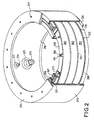
- crowns 209 and 210 identical to the crowns 204, and from the acoustic point of view of the crowns 211 and 212 of relatively thick elastic material, 4 mm thick rubber for example, which separate these profiles emitting piezoelectric segments.
- these crowns have have been shown cut to show the superposition of the layers, in particular at the level of the hold 109.
- the sections 207 and 208 therefore have a flat lower face making it possible to rest on the rubber crowns and an upper face having external peripheral 213 and internal 214 grooves.
- the external and internal faces of this assembly are covered with two layers of rubber respectively 215 and 216 which form envelopes intended to ensure the tightness of the stack with respect to external agents, in particular sea water in which the device must be submerged.
- These envelopes have at their ends rims 217 and 218, obtained for example by machining or by molding, which come to be embedded respectively in the grooves 213 and 214.
- these flanges have a median shoulder 222 which abuts against a mediating circular projection 223 formed on the top of the profiles and concentric with the groove 213, so as to be able to center each flange without difficulty on the corresponding profile, by fitting it like a cover.
- the crowns can be machined to eliminate the internal excess thickness 230, corresponding to the offset in height of the groove 314 relative to the groove 215 , in order to minimize the inactive weight of the assembly as much as possible.
- a connector is used multifilaire 224, which is placed in a nozzle 225 produced in the same material, for example rubber, as the inner casing 216.
- This nozzle is fixed on the outside face of this inside envelope of so as to project into the interior space of the transducer. Fixation is carried out by any known means to connect pieces of material of this nature, by vulcanization for example.
- valve 226, allowing the filling interior space of the transducer with a suitable fluid, oil for example, is fixed with a 227 cap on the inner casing 216.
- a transmit antenna In an exemplary embodiment of such a transmit antenna, three rings were assembled, each comprising 14 segments and the interior and exterior diameters are approximately 450 and 600 mm.
- the active mass / total mass ratio of this device is greater than 75%, which is a particularly remarkable value. otherwise the antenna thus obtained is, as can be seen, entirely can be dismantled and reassembled, making it easy to replace and quickly a segment which would prove to be defective.
- the support structure of a towed fish for example, we use one or the other, or two flanges 219 and 220.
- the layers of rubber 211 then allows acoustically decouple the antenna from this structure.
Landscapes
- Engineering & Computer Science (AREA)
- Mechanical Engineering (AREA)
- Transducers For Ultrasonic Waves (AREA)
- Measurement Of Velocity Or Position Using Acoustic Or Ultrasonic Waves (AREA)
- Apparatuses For Generation Of Mechanical Vibrations (AREA)
Description
- la figure 1, un couronne élémentaire, conforme à l'état de l'art;
- la figure 2, une vue en coupe écorchée partielle d'une antenne selon l'invention;
- la figure 3, une vue en perspective d'un coin de serrage d'une couronne et d'un tirant d'assemblage qui lui est associé; et
- la figure 4, une vue en coupe de deux couronnes profilées d'extrémité permettant l'assemblage des anneaux élémentaires.
Claims (7)
- Antenne d'émission acoustique annulaire démontable, du type comprenant au moins un anneau précontraint (201) formé d'un ensemble de segment piézoélectrique (101) groupés pour former des secteurs sensiblement identiques (102), de pièces d'extrémité (106) fixées sur ces secteurs pour délimiter entre eux des intervalles en forme de coin, et de cales de serrage (109) en forme de coin adaptées à ces intervalles et placées dans ceux-ci, une frette conformatrice (108) permettant de maintenir l'ensemble des secteurs, et des moyens de serrage (110-112) permettant de faire glisser les cales de serrage vers l'intérieur de l'anneau pour précontraindre les segments sur la frette, caractérisé en ce qu'elle comprend un ensemble d'anneaux précontraints (201-203) sensiblement identiques superposés les uns au dessus des autres de manière à ce que les cales de serrage soit en vis-à-vis les unes des autres, deux couronnes profilées (207,208) de même diamètre que les anneaux précontraints et placées respectivement aux deux extrémités de l'empilage, et un ensemble de tirants de fixation (206) traversant respectivement les groupes de cales superposées par l'intermédiaire de trous 205 longitudinaux forés dans ces cales pour être fixés aux couronnes profilées afin de presser les anneaux les uns contre les autres.
- Antenne selon la revendication 1, caractérisée en ce qu'elle comprend deux enveloppes en matériau élastique (215-216) venant recouvrir respectivement les faces extérieure et intérieure du cylindre formé par l'empilement d'anneaux, et comportant chacune des rebords (217,218) venant s'ancrer dans des gorges périphériques (213,214) ménagées dans les faces des couronnes profilées situées de l'autre côté des faces de ces couronnes venant s'appuyer sur les anneaux.
- Antenne selon la revendication 2, caractérisée en ce qu'elle comprend en outre deux flasques en forme de couronnes (219-220) fixées respectivement sur lesdites surfaces des couronnes profilées pour maintenir lesdits rebords dans lesdites gorges périphériques.
- Antenne selon l'une quelconques des revendications 1 à 3, caractérisée en ce qu'elle comporte des couronnes isolantes (204) insérées entre les anneaux superposés.
- Antenne selon l'une quelconque des revendications 1 à 4, caractérisée en ce qu'elle comporte en outre des anneaux en matière élastique (211) interposés entre les couronnes profilées et les anneaux isolants situés sous ces couronnes pour découpler acoustiquement les anneaux de la structure de maintien de ceux-ci.
- Antenne selon l'une quelconque des revendications 1 à 5, caractérisée en ce que les tirants de fixation (206) forment des vis dont les têtes viennent s'appuyer sur la face extérieure de l'une des couronnes profilées et dont les autres extrémités sont filetées et viennent se visser dans des trous borgnes taraudés, forés sur la face intérieur de l'autre couronne profilée.
- Antenne selon l'une quelconque des revendications 1 à 6, caractérisée en ce que le connecteur d'alimentation de l'antenne 224 et l'embout de gonflage de celle-ci (226) sont fixés sur des supports élastiques (225-227) eux-mêmes fixés sur la paroi externe de l'enveloppe intérieure (216) de protection de l'antenne.
Applications Claiming Priority (3)
| Application Number | Priority Date | Filing Date | Title |
|---|---|---|---|
| FR9802912 | 1998-03-10 | ||
| FR9802912A FR2776161B1 (fr) | 1998-03-10 | 1998-03-10 | Antenne d'emission acoustique annulaire demontable |
| PCT/FR1999/000523 WO1999046059A1 (fr) | 1998-03-10 | 1999-03-09 | Antenne d'emission acoustique annulaire demontable |
Publications (2)
| Publication Number | Publication Date |
|---|---|
| EP1062055A1 EP1062055A1 (fr) | 2000-12-27 |
| EP1062055B1 true EP1062055B1 (fr) | 2004-05-12 |
Family
ID=9523862
Family Applications (1)
| Application Number | Title | Priority Date | Filing Date |
|---|---|---|---|
| EP99907670A Expired - Lifetime EP1062055B1 (fr) | 1998-03-10 | 1999-03-09 | Antenne d'emission acoustique annulaire demontable |
Country Status (7)
| Country | Link |
|---|---|
| US (1) | US6345014B1 (fr) |
| EP (1) | EP1062055B1 (fr) |
| JP (1) | JP4031198B2 (fr) |
| AU (1) | AU747667B2 (fr) |
| DE (1) | DE69917235T2 (fr) |
| FR (1) | FR2776161B1 (fr) |
| WO (1) | WO1999046059A1 (fr) |
Families Citing this family (5)
| Publication number | Priority date | Publication date | Assignee | Title |
|---|---|---|---|---|
| FR2800229B1 (fr) | 1999-10-22 | 2002-04-05 | Thomson Marconi Sonar Sas | Transducteur acoustique sous-marin a large bande |
| FR2809580B1 (fr) | 2000-05-26 | 2002-08-30 | Thomson Marconi Sonar Sas | Transducteur electrodynamique pour acoustique sous-marine |
| US7500398B2 (en) * | 2003-01-17 | 2009-03-10 | Kistler Holding, Ag | Prestressing element for sensors |
| FR3015785B1 (fr) | 2013-12-20 | 2015-12-25 | Thales Sa | Antenne omnidirectionnelle compacte pour sonar trempe |
| FR3087542B1 (fr) | 2018-10-22 | 2021-01-15 | Thales Sa | Antenne d'emission acoustique |
Family Cites Families (17)
| Publication number | Priority date | Publication date | Assignee | Title |
|---|---|---|---|---|
| US3243767A (en) * | 1962-04-30 | 1966-03-29 | Paul M Kendig | Electroacoustic transducer for detection of low level acoustic signals over a broad frequency range |
| US3559162A (en) * | 1969-04-14 | 1971-01-26 | Sparton Corp | Unitary directional sonar transducer |
| BE757591A (fr) | 1969-11-25 | 1971-03-16 | Thomson Csf | Perfectionnements aux domes de systemes sonars et procede de leur fabrication |
| FR2290812A1 (fr) | 1974-11-08 | 1976-06-04 | Thomson Csf | Transducteur electroacoustique pour immersion profonde |
| GB1518138A (en) | 1974-12-17 | 1978-07-19 | Thomson Csf | Cooling device for components which dissipate large amounts of heat |
| FR2589248B1 (fr) | 1978-02-17 | 1988-01-22 | Thomson Csf | Amelioration des systemes d'autoguidage acoustique de vehicules sous-marins |
| FR2431419A1 (fr) | 1978-07-18 | 1980-02-15 | Thomson Csf | Bouee aeroportee largable |
| FR2450193A1 (fr) | 1979-02-27 | 1980-09-26 | Thomson Csf | Bouee aeroportee largable a declenchement inertiel |
| FR2464179A2 (fr) | 1979-08-28 | 1981-03-06 | Thomson Csf | Bouee aeroportee largable |
| FR2622333B1 (fr) | 1987-10-27 | 1990-01-26 | Thomson Csf | Revetement anechoique pour ondes acoustiques |
| FR2656971B1 (fr) | 1990-01-05 | 1992-09-04 | Thomson Csf | Hydrophone basse frequence et antenne sonar comportant de tels hydrophones. |
| FR2672179B1 (fr) | 1991-01-25 | 1993-04-16 | Thomson Csf | Transducteur acoustique flextenseur pour immersion profonde. |
| US5630837A (en) * | 1993-07-01 | 1997-05-20 | Boston Scientific Corporation | Acoustic ablation |
| FR2725684A1 (fr) | 1994-10-18 | 1996-04-19 | Thomson Csf | Bouee aeroportee largable |
| FR2728755B1 (fr) * | 1994-12-23 | 1997-01-24 | Thomson Csf | Transducteur acoustique en anneau precontraint |
| FR2730894B3 (fr) | 1995-02-21 | 1997-03-14 | Thomson Csf | Procede de fabrication d'une carte electronique a refroidissement par conduction thermique |
| FR2764160B1 (fr) | 1997-05-27 | 1999-08-27 | Thomson Marconi Sonar Sas | Transducteur electrodynamique pour acoustique sous-marine |
-
1998
- 1998-03-10 FR FR9802912A patent/FR2776161B1/fr not_active Expired - Lifetime
-
1999
- 1999-03-09 DE DE69917235T patent/DE69917235T2/de not_active Expired - Lifetime
- 1999-03-09 EP EP99907670A patent/EP1062055B1/fr not_active Expired - Lifetime
- 1999-03-09 US US09/623,851 patent/US6345014B1/en not_active Expired - Lifetime
- 1999-03-09 AU AU27323/99A patent/AU747667B2/en not_active Expired
- 1999-03-09 JP JP2000535464A patent/JP4031198B2/ja not_active Expired - Fee Related
- 1999-03-09 WO PCT/FR1999/000523 patent/WO1999046059A1/fr not_active Ceased
Also Published As
| Publication number | Publication date |
|---|---|
| US6345014B1 (en) | 2002-02-05 |
| DE69917235D1 (de) | 2004-06-17 |
| FR2776161B1 (fr) | 2000-05-26 |
| AU747667B2 (en) | 2002-05-16 |
| JP4031198B2 (ja) | 2008-01-09 |
| WO1999046059A1 (fr) | 1999-09-16 |
| JP2002505953A (ja) | 2002-02-26 |
| AU2732399A (en) | 1999-09-27 |
| DE69917235T2 (de) | 2005-05-04 |
| FR2776161A1 (fr) | 1999-09-17 |
| EP1062055A1 (fr) | 2000-12-27 |
Similar Documents
| Publication | Publication Date | Title |
|---|---|---|
| EP0462037B1 (fr) | Transducteur électro-acoustique immergé | |
| FR2668836A1 (fr) | Transducteur acoustique de puits. | |
| EP0156697A1 (fr) | Perfectionnements aux supports antivibratoires hydrauliques | |
| EP1062055B1 (fr) | Antenne d'emission acoustique annulaire demontable | |
| EP0204608A1 (fr) | Support de câbles pour poteau électrique | |
| FR2671844A1 (fr) | Soufflet a ondes courbes. | |
| EP0303547B1 (fr) | Transducteur omnidirectionnel d'ondes élastiques à large bande passante | |
| EP1249827B1 (fr) | Colonne acoustique, et antenne cylindrique pour sonar passif utilisant une telle colonne | |
| EP0799097B1 (fr) | Transducteur acoustique en anneau precontraint | |
| WO2003047770A1 (fr) | Antenne acoustique a grande puissance d'emission | |
| FR2720585A1 (fr) | Transducteur électro acoustique antenne sonar ouverts. | |
| EP1409897B1 (fr) | Joint de culasse comprenant un stoppeur bord a bord | |
| CA2150449C (fr) | Antenne acoustique passive absorbante | |
| EP0762381A1 (fr) | Transducteur électroacoustique flextenseur | |
| EP4282543B1 (fr) | Transducteur cmut et procede de fabrication d'un transducteur cmut | |
| FR2739521A1 (fr) | Transducteur electroacoustique et antenne de sonar equipee d'un tel transducteur | |
| EP1684917B1 (fr) | Antenne sonar hf a structure composite 1-3 | |
| FR2720588A1 (fr) | Perfectionnement acoustique aux antennes sonar. | |
| FR2720586A1 (fr) | Antenne sonar à têtes démontables. | |
| EP0684085A1 (fr) | Antenne sonar ouverte comportant des transducteurs électro-acoustiques | |
| EP0331591A1 (fr) | Capsule électroacoustique à membrane piézoélectrique | |
| FR2720587A1 (fr) | Perfectionnement aux antennes sonar munies d'une contre masse commune. | |
| EP1844198A1 (fr) | Systeme de verrouillage complementaire des jambes sur un pont d'une plate-forme d'exploitation en mer et procedes de pose d'un tel systeme de verrouillage | |
| CH688927B5 (fr) | Dispositif d'alarme notamment pour montre de plongée. | |
| CA2202301C (fr) | Emetteur acoustique sous-marin pour grande immersion |
Legal Events
| Date | Code | Title | Description |
|---|---|---|---|
| PUAI | Public reference made under article 153(3) epc to a published international application that has entered the european phase |
Free format text: ORIGINAL CODE: 0009012 |
|
| 17P | Request for examination filed |
Effective date: 20000810 |
|
| AK | Designated contracting states |
Kind code of ref document: A1 Designated state(s): DE GB IT |
|
| 17Q | First examination report despatched |
Effective date: 20020108 |
|
| GRAP | Despatch of communication of intention to grant a patent |
Free format text: ORIGINAL CODE: EPIDOSNIGR1 |
|
| GRAS | Grant fee paid |
Free format text: ORIGINAL CODE: EPIDOSNIGR3 |
|
| GRAA | (expected) grant |
Free format text: ORIGINAL CODE: 0009210 |
|
| AK | Designated contracting states |
Kind code of ref document: B1 Designated state(s): DE GB IT |
|
| REG | Reference to a national code |
Ref country code: GB Ref legal event code: FG4D Free format text: NOT ENGLISH |
|
| REF | Corresponds to: |
Ref document number: 69917235 Country of ref document: DE Date of ref document: 20040617 Kind code of ref document: P |
|
| GBT | Gb: translation of ep patent filed (gb section 77(6)(a)/1977) |
Effective date: 20040816 |
|
| PLBE | No opposition filed within time limit |
Free format text: ORIGINAL CODE: 0009261 |
|
| STAA | Information on the status of an ep patent application or granted ep patent |
Free format text: STATUS: NO OPPOSITION FILED WITHIN TIME LIMIT |
|
| 26N | No opposition filed |
Effective date: 20050215 |
|
| PGFP | Annual fee paid to national office [announced via postgrant information from national office to epo] |
Ref country code: GB Payment date: 20180306 Year of fee payment: 20 Ref country code: DE Payment date: 20180227 Year of fee payment: 20 |
|
| PGFP | Annual fee paid to national office [announced via postgrant information from national office to epo] |
Ref country code: IT Payment date: 20180321 Year of fee payment: 20 |
|
| REG | Reference to a national code |
Ref country code: DE Ref legal event code: R071 Ref document number: 69917235 Country of ref document: DE |
|
| REG | Reference to a national code |
Ref country code: GB Ref legal event code: PE20 Expiry date: 20190308 |
|
| PG25 | Lapsed in a contracting state [announced via postgrant information from national office to epo] |
Ref country code: GB Free format text: LAPSE BECAUSE OF EXPIRATION OF PROTECTION Effective date: 20190308 |
|
| P01 | Opt-out of the competence of the unified patent court (upc) registered |
Effective date: 20230606 |