EP1062970A2 - Ensemble électrode - Google Patents
Ensemble électrode Download PDFInfo
- Publication number
- EP1062970A2 EP1062970A2 EP00250202A EP00250202A EP1062970A2 EP 1062970 A2 EP1062970 A2 EP 1062970A2 EP 00250202 A EP00250202 A EP 00250202A EP 00250202 A EP00250202 A EP 00250202A EP 1062970 A2 EP1062970 A2 EP 1062970A2
- Authority
- EP
- European Patent Office
- Prior art keywords
- electrode
- line
- electrical
- surface areas
- switching
- Prior art date
- Legal status (The legal status is an assumption and is not a legal conclusion. Google has not performed a legal analysis and makes no representation as to the accuracy of the status listed.)
- Granted
Links
- 238000000034 method Methods 0.000 claims abstract description 4
- 239000003990 capacitor Substances 0.000 claims description 7
- 238000004146 energy storage Methods 0.000 claims description 6
- 230000013011 mating Effects 0.000 claims description 2
- 230000006378 damage Effects 0.000 claims 1
- 230000000638 stimulation Effects 0.000 description 8
- 239000002184 metal Substances 0.000 description 7
- 230000007935 neutral effect Effects 0.000 description 7
- 239000004020 conductor Substances 0.000 description 6
- 230000005669 field effect Effects 0.000 description 4
- 230000006835 compression Effects 0.000 description 3
- 238000007906 compression Methods 0.000 description 3
- 238000012360 testing method Methods 0.000 description 3
- 238000004519 manufacturing process Methods 0.000 description 2
- 230000005540 biological transmission Effects 0.000 description 1
- 238000007664 blowing Methods 0.000 description 1
- 210000005003 heart tissue Anatomy 0.000 description 1
- 238000009413 insulation Methods 0.000 description 1
- 230000015654 memory Effects 0.000 description 1
- 125000006850 spacer group Chemical group 0.000 description 1
Images


Classifications
-
- A—HUMAN NECESSITIES
- A61—MEDICAL OR VETERINARY SCIENCE; HYGIENE
- A61N—ELECTROTHERAPY; MAGNETOTHERAPY; RADIATION THERAPY; ULTRASOUND THERAPY
- A61N1/00—Electrotherapy; Circuits therefor
- A61N1/02—Details
- A61N1/04—Electrodes
- A61N1/05—Electrodes for implantation or insertion into the body, e.g. heart electrode
- A61N1/056—Transvascular endocardial electrode systems
Definitions
- the invention relates to an implantable electrode arrangement, which has an electrode line with several electrically conductive surface areas in the area of the distal end for delivering electrical signals to a heart and / or for recording of signals from a heart, which are electrical via the electrode line with a cardioelectric recording and / or emitting electrical signals Device for a defibrillator or pacemaker can be connected are.
- Electrode arrangements with one electrode line and several electrically conductive Surface areas, for example of tip or ring electrodes on The distal end of the electrode line are, for example, from EP 0 571 797, the US 4,484,352 and US 4,628,934.
- the known electrode arrangements are electrical as stimulation or sensing electrodes conductive surface sections individually by means of electrical lines, which in the Electrode lead run, connected to a pacemaker or defibrillator.
- a disadvantage of the known electrode arrangements is that they regularly only with specially adapted pacemakers or Defibrillators can be used that allow the proximal end of the Electrode lead to contact all leads leading to the electrical lead conductive surface areas.
- Electrode arrangements are common in which only one or two electrical conductors run, depending on whether the electrode arrangement for unipolar or for bipolar stimulation is provided.
- Electrode leads with a single wire connection between the proximal end the electrode lead and the electrically conductive surface areas on the distal are suitable for unipolar stimulation Stimulation pulses between the electrically conductive surface areas on distal end of the electrode lead and a neutral electrode such as in a pacemaker housing.
- a neutral electrode such as in a pacemaker housing.
- bipolar stimulation in which the stimulation energy between different the electrically conductive surface areas at the distal end of the electrode lead is delivered.
- a two-wire connection between the proximal and distal ends is provided is produced via two separate electrical lines.
- the aim of the invention is to take advantage of multiple electrode arrangements of electrically conductive and individually controllable surface areas too for pacemakers or defibrillators with conventional one or two-wire connections to make available.
- an electrode arrangement at the beginning achieved type which is characterized by switching means arranged in this way are designed so that the connection between individual of the electrically conductive Surface areas and the cardioelectric devices in the area of Electrode line can be switched on or off permanently.
- Such an electrode arrangement initially allows any of the electrically conductive surface areas by picking up or delivering electrical signals and then permanently via a conventional single-wire or two-wire line in the electrode lead with the cardioelectric device such as a defibrillator or to use pacemakers.
- the switching means are designed such that they maintain their switching state when de-energized.
- the switching means are via the electrode line electrically controllable.
- the electrode line preferably has one Decoder on the one hand with the switching means and on the other hand at least an electrical line - for example the usual single-wire or two-wire line, which the electrically conductive surface areas with the pacemaker connects - is connected.
- the decoder is designed so that it over this electrical line control signals received and the switching means depending which can control control signals individually.
- Such an electrode arrangement In the minimum case only needs a single electrical conductor, that from the proximal End of the electrode line to the switching means, the decoder and the electrical conductive surface areas at the distal end of the electrode lead.
- the reference potential for the control signals can then, for example, be via a neutral electrode with the pacemaker housing. After this Can determine the most suitable electrodes or electrode combinations this then permanently with the help of the decoder and the switching means electrical lead in the electrode lead with, for example, a pacemaker get connected. This can be a common pacemaker for then the advantages of the individually determined, most suitable Result in electrode configurations.
- the electrode arrangement preferably an energy storage device which is connected to the switching means and / or the decoder and connected with a lower power the electrode line can be charged when it is connected via the switching means and / or the decoder can give up.
- the energy store is preferably an electrical capacitor, of high impedance, for example, via fine wire line and neutral electrode is charged, and the electrical energy accumulated in this way is short-term can deliver for switching the switching elements.
- This can be, for example Turning on a power field transistor or blowing a thyristor his.
- a switching connection is permanently established or permanently separated.
- the latter case is the preferred one in which the switching elements are designed so that to switch off a connection between the Electrode line and an electrically conductive surface area the connection is permanently destructible.
- the energy store is preferably for giving energy required for this.
- an electrode arrangement which contains control means on the input side via at least one electrical line for signals to or from the electrical conductive surface areas connectable to the cardioelectric device and on the output side with the electrically conductive surface areas are connected, which are designed such that they through through the electrical line incoming control signals can be controlled such that individual surface areas or combinations of surface areas with the cardioelectric device for emitting and receiving signals for determining for the permanent connection with those suitable for the cardioelectric device electrically conductive surface sections are connectable.
- the latter So variant does not concern the permanent connection of the electrically conductive Surface areas with the cardioelectric device, but the test Connect the surface areas to the device before permanent Setting a suitable electrode combination.
- An alternative preferred electrode arrangement is characterized by a relative to the electrode line longitudinally or rotatably guided stylet, the actuators for mechanical switching elements with which the connection between individual of the electrically conductive surface areas and the cardioelectric device in the area of the electrode line permanently on or can be switched off.
- the switching elements can shift or rotate the switching elements in the electrode line be that they selectively make contact between one or more of the electrically conductive surface areas and an electrical line in the Establish or interrupt the electrode lead. Since the corresponding mechanical Do not change switching elements without actuation by the stylet in this way a connection between the electrically conductive surface areas and the electrical conductor in the electrode line is permanently manufactured or interrupted.
- an electrode arrangement is used preferred, in which the switching elements in the region of the distal End of the electrode line are arranged longitudinally or rotatably and with at least one electrical line in the electrode line in electrical Stand in contact and continue to have contact areas that are in one of at least two possible positions of the switching elements one with at least one electrically conductive surface area related mating contact contact and continue to have circuits with which a switching element by means of corresponding counter cams on the stylet in this way by means of the stylet It is movable that the switching means by means of the stylet each in a surface area with the cardioelectrical device connecting and a Surface area separating position from the cardioelectric device are movable.
- the goal mentioned at the outset is also achieved by means of a method achieved to operate the electrode arrangement described, in which initially surface areas suitable for signal recording and / or stimulation are determined and then the suitable surface areas permanently be connected to at least one electrical line of the electrode line, while the remaining surface areas are permanently from the electrical wire be separated.
- the procedure is therefore two-stage, first being preliminary Connections between the electrically conductive surface areas and, for example a pacemaker made to the electrically conductive Test surface areas or combinations with regard to their suitability. To serve the tax resources already mentioned. Then the most suitable Surface areas permanently with one to the proximal end of the electrode lead leading electrical line connected or accordingly all except the most suitable surface areas permanently from the electrical line Cut.
- the distal end shown in Figure 1 comprises an electrode line 10 with a insulating, sleeve 12 and embedded ring electrodes 14 and one Tip electrode 16 at the extreme end of the electrode line 10.
- a coiled electrical line 18 leading to Transmission of electrical signals from and to the electrodes 14 and 16 is used.
- the Electrodes 14 and 16 can be made of metal, for example, it is essential that the electrodes 14 and 16 electrically conductive surface areas of the electrode line 10, which are at least partially connected to the electrical line 18 are connectable.
- the structure of the electrode line 10 is that shown in FIG. 2 Longitudinal section through the electrode line 10 in the area of two ring electrodes 14 can be seen. You can see the coiled electrical line 18, the runs within the insulating sheath 12.
- the field effect transistors 20 are power transistors with less Contact resistance when switched on. They set one each Switching means for connecting or interrupting an electrical connection between the line 18 and a respective ring electrode 14. Driven the field effect transistors 20 from the control unit or the decoder 22nd The control unit or decoder 22 has two control inputs, one of which one with the electrical line 18 and the other with a ring electrode each 14 is connected.
- the control unit 22 can control signals via the control inputs record, for example, from a pacemaker to the electrical Line 18 and a neutral electrode such as the pacemaker housing are and accordingly represent themselves as a potential sequence between the line 18 and a ring electrode 14.
- the ring electrode 14 is connected to the neutral electrode via a body in which it is inserted.
- a capacitor 24, which also serves to supply power to the control unit 22 is arranged between the line 18 and a ring electrode 14 in each case.
- This Capacitor 24 is on the one hand and on the other hand via the electrical line the ring electrode 14 and the corresponding neutral electrode (not shown) powered by the pacemaker and charged with high resistance.
- any of the electrodes 14 and 16 can be controlled via corresponding control signals by means of the control units 22 and the field effect transistors 20 with the line 18 connected or disconnected from it.
- EPROMs i.e. electrically programmable read memories
- electrically programmable read memories are also used, which are configured via appropriate control signals and the desired ones Make connections to electrodes 14 and 16 and lead 18.
- the appropriate if necessary Control means using electrical energy stored in a capacitor be blown to make a connection between an electrode 14 or 16 and permanently interrupt line 18.
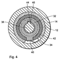
- FIGS. 3a and 3b and 4 mechanical variant provided.
- the outer structure of the electrode line 10 is identical to that Variants previously described: in an insulating sheath 12 are ring electrodes 14 embedded in the form of metal rings.
- the electrical line is in the range of pictured distal end of the electrode line not as a continuous wire coil formed, but is in sections of compression springs 30 and each a metal body 32 of mechanical switching elements 34 is formed.
- Electrode line 10 for the sake of clarity in the partially disassembled state demonstrate.
- the stylet 36 shown in FIG. 3a runs coaxial to the electrode line 10 'in the same and thus penetrates the switching elements 34 and runs within the compression springs 30.
- the switching elements 34 are formed by spacer sleeves 38 with respect to their axial position in the electrode line 10 'so that the Switching elements 34 lie opposite the ring electrodes 14 on the inside thereof.
- the switching elements 34 can be rotated about the longitudinal axis of the electrode line 10 ' arranged. In each case a switching contact 40 of the ring electrodes 14 contacts the Outer surface of the switching elements 34.
- the sliding contact 40 may make electrical contact between the produce metal body 32 of switching element 34 and ring electrode 14, when the switching element 34 is in a suitable angular position.
- the switching element 34 prevents insulation 42 on the outer surface of the switching element 34 electrical contact between the metal body 32 of the switching element 34 and the ring electrode 14.
- FIG Position of the switching element 34 via the compression springs 30 and the metal Body 32 of the switching elements 34 and the sliding contact 40 an electrical Connection between the electrical line in the electrode line 10 'and the Ring electrode 14.
- the switching element 34 is in a different one than that Angular position shown is the electrical connection between the electrical Line and the electrode 14 interrupted.
- the stylet 36 For selecting the angular and thus the switching positions of the switching elements 34 serves the stylet 36, which is rotatable and longitudinally displaceable in the electrode line 10 ' is stored.
- the stylet 36 has switching cams 44, each in one Groove 46 is engaged in the metal body 32 of the switching element 34 can be. This is done by moving the stylet 36 longitudinally The distance between the switching cams 44 in the longitudinal direction of the stylet 36 is selected that only one switching cam engages in a groove 46 of a switching element 34. That switching element 34, into which switching cam 44 of stylet 36 engages, can by rotating the stylet 36 about its longitudinal axis in an angular position are brought and thus into an end connection to the respective ring electrode earth 14 manufacturing or separating angular position.
Landscapes
- Health & Medical Sciences (AREA)
- Heart & Thoracic Surgery (AREA)
- Vascular Medicine (AREA)
- Cardiology (AREA)
- Engineering & Computer Science (AREA)
- Biomedical Technology (AREA)
- Nuclear Medicine, Radiotherapy & Molecular Imaging (AREA)
- Radiology & Medical Imaging (AREA)
- Life Sciences & Earth Sciences (AREA)
- Animal Behavior & Ethology (AREA)
- General Health & Medical Sciences (AREA)
- Public Health (AREA)
- Veterinary Medicine (AREA)
- Electrotherapy Devices (AREA)
Applications Claiming Priority (2)
| Application Number | Priority Date | Filing Date | Title |
|---|---|---|---|
| DE19930271A DE19930271A1 (de) | 1999-06-25 | 1999-06-25 | Elektrodenanordnung |
| DE19930271 | 1999-06-25 |
Publications (3)
| Publication Number | Publication Date |
|---|---|
| EP1062970A2 true EP1062970A2 (fr) | 2000-12-27 |
| EP1062970A3 EP1062970A3 (fr) | 2003-01-15 |
| EP1062970B1 EP1062970B1 (fr) | 2005-11-09 |
Family
ID=7913258
Family Applications (1)
| Application Number | Title | Priority Date | Filing Date |
|---|---|---|---|
| EP00250202A Expired - Lifetime EP1062970B1 (fr) | 1999-06-25 | 2000-06-23 | Ensemble électrode |
Country Status (3)
| Country | Link |
|---|---|
| US (1) | US6421567B1 (fr) |
| EP (1) | EP1062970B1 (fr) |
| DE (2) | DE19930271A1 (fr) |
Cited By (1)
| Publication number | Priority date | Publication date | Assignee | Title |
|---|---|---|---|---|
| EP2087922A1 (fr) | 2008-02-05 | 2009-08-12 | BIOTRONIK CRM Patent AG | Fil-guide multipolaire et sonde d'électrodes |
Families Citing this family (25)
| Publication number | Priority date | Publication date | Assignee | Title |
|---|---|---|---|---|
| AU6953300A (en) * | 1999-07-07 | 2001-01-22 | Cardiac Pacemakers, Inc. | Endocardial electrode assembly having conductive fixation features |
| US7286878B2 (en) * | 2001-11-09 | 2007-10-23 | Medtronic, Inc. | Multiplexed electrode array extension |
| US20030149456A1 (en) * | 2002-02-01 | 2003-08-07 | Rottenberg William B. | Multi-electrode cardiac lead adapter with multiplexer |
| EP1581102A4 (fr) | 2002-12-11 | 2006-12-20 | Proteus Biomedical Inc | Procede et systeme permettant de controler et traiter des parametres hemodynamiques |
| WO2006105474A2 (fr) | 2005-03-31 | 2006-10-05 | Proteus Biomedical, Inc. | Optimisation automatisee d'entrainement electrosystolique a electrodes multiples destine a la resynchronisation cardiaque |
| US20060122679A1 (en) * | 2004-12-03 | 2006-06-08 | Wengreen Eric J | Semiconductor-gated cardiac lead and method of use |
| WO2007021804A2 (fr) | 2005-08-12 | 2007-02-22 | Proteus Biomedical, Inc. | Evaluation de la vitesse de conduction de l'onde de depolarisation |
| WO2007053065A1 (fr) * | 2005-10-31 | 2007-05-10 | St. Jude Medical Ab | Conducteur implantable dote d’une electrode de stimulation et d’une electrode d’ablation deconnectable |
| US7650184B2 (en) * | 2005-12-01 | 2010-01-19 | Boston Scientific Neuromodulation Corporation | Cylindrical multi-contact electrode lead for neural stimulation and method of making same |
| US7835803B1 (en) * | 2006-01-17 | 2010-11-16 | Boston Scientific Neuromodulation Corporation | Lead assemblies with one or more switching networks |
| US7846158B2 (en) * | 2006-05-05 | 2010-12-07 | Covidien Ag | Apparatus and method for electrode thermosurgery |
| US8219207B2 (en) * | 2007-03-08 | 2012-07-10 | Medtronic, Inc. | Thermal switch for implantable medical devices |
| WO2008111986A1 (fr) * | 2007-03-09 | 2008-09-18 | Medtronic, Inc. | Conception de fil électrique pour dispositif médical destiné à empêcher la transmission de courants électriques dangereux à un patient |
| WO2009042063A1 (fr) * | 2007-09-27 | 2009-04-02 | Cardiac Pacemakers, Inc. | Dérivation implantable comprenant un condensateur d'électrostimulation |
| EP2252365B1 (fr) * | 2008-02-21 | 2013-10-16 | Boston Scientific Neuromodulation Corporation | Dispositif temporaire d'identification d'un fil de neurostimulation |
| WO2009131749A2 (fr) | 2008-02-28 | 2009-10-29 | Proteus Biomedical, Inc. | Implémentation de circuit intégré et système, dispositif et procédé de contrôle des défaillances |
| US8600518B2 (en) * | 2008-04-30 | 2013-12-03 | Boston Scientific Neuromodulation Corporation | Electrodes for stimulation leads and methods of manufacture and use |
| JP2012522605A (ja) * | 2009-04-02 | 2012-09-27 | プロテウス バイオメディカル インコーポレイテッド | 埋め込み型リード線のための方法及び装置 |
| JP2012525206A (ja) | 2009-04-29 | 2012-10-22 | プロテウス バイオメディカル インコーポレイテッド | 移植可能なデバイスのためのリード線のための方法および装置 |
| JP5730872B2 (ja) | 2009-07-23 | 2015-06-10 | プロテウス デジタル ヘルス, インコーポレイテッド | 固体薄膜コンデンサ |
| DE102010019648B4 (de) | 2010-05-06 | 2019-07-11 | Acandis Gmbh | Elektrode und Verfahren zur Herstellung einer derartigen Elektrode |
| US8718770B2 (en) | 2010-10-21 | 2014-05-06 | Medtronic, Inc. | Capture threshold measurement for selection of pacing vector |
| US8355784B2 (en) | 2011-05-13 | 2013-01-15 | Medtronic, Inc. | Dynamic representation of multipolar leads in a programmer interface |
| EP3009165A1 (fr) | 2014-10-16 | 2016-04-20 | BIOTRONIK SE & Co. KG | Sonde electrique implantable |
| US11717675B2 (en) | 2019-08-02 | 2023-08-08 | Biosense Webster (Israel) Ltd. | Patient-safe electromechanical switching for pacing with a catheter having multiple electrodes |
Citations (3)
| Publication number | Priority date | Publication date | Assignee | Title |
|---|---|---|---|---|
| US4484352A (en) | 1983-02-07 | 1984-11-20 | Katzin Lawrence F | Reclosable plastic bag |
| US4628934A (en) | 1984-08-07 | 1986-12-16 | Cordis Corporation | Method and means of electrode selection for pacemaker with multielectrode leads |
| EP0571797A1 (fr) | 1992-05-25 | 1993-12-01 | Pacesetter AB | Appareil de stimulation cardiaque |
Family Cites Families (9)
| Publication number | Priority date | Publication date | Assignee | Title |
|---|---|---|---|---|
| FR2566201B1 (fr) * | 1984-06-13 | 1988-02-05 | Commissariat Energie Atomique | Dispositif electronique statique multiplieur de commande |
| US4848352A (en) | 1987-02-13 | 1989-07-18 | Telectronics, N.V. | Method for cardiac pacing and sensing using combination of electrodes |
| CA2065373C (fr) * | 1989-08-15 | 2000-05-16 | Hendrik Mario Geysen | Dispositif de commutation |
| US5018523A (en) * | 1990-04-23 | 1991-05-28 | Cardiac Pacemakers, Inc. | Apparatus for common mode stimulation with bipolar sensing |
| SE9202521D0 (sv) * | 1992-09-02 | 1992-09-02 | Siemens Elema Ab | Anordning foer stimulering av levande vaevnad |
| US5480421A (en) * | 1992-10-30 | 1996-01-02 | Medtronic, Inc. | Lead with stylet capture member |
| US5824030A (en) * | 1995-12-21 | 1998-10-20 | Pacesetter, Inc. | Lead with inter-electrode spacing adjustment |
| US5843135A (en) * | 1997-10-20 | 1998-12-01 | Medtronic, Inc. | Pacing system with lead having a single conductor for connecting to pressure sensor and electrode |
| US5968086A (en) * | 1998-02-23 | 1999-10-19 | Medtronic, Inc. | Pacing and cardioversion lead systems with shared lead conductors |
-
1999
- 1999-06-25 DE DE19930271A patent/DE19930271A1/de not_active Withdrawn
-
2000
- 2000-06-23 EP EP00250202A patent/EP1062970B1/fr not_active Expired - Lifetime
- 2000-06-23 DE DE50011541T patent/DE50011541D1/de not_active Expired - Lifetime
- 2000-06-26 US US09/603,077 patent/US6421567B1/en not_active Expired - Lifetime
Patent Citations (3)
| Publication number | Priority date | Publication date | Assignee | Title |
|---|---|---|---|---|
| US4484352A (en) | 1983-02-07 | 1984-11-20 | Katzin Lawrence F | Reclosable plastic bag |
| US4628934A (en) | 1984-08-07 | 1986-12-16 | Cordis Corporation | Method and means of electrode selection for pacemaker with multielectrode leads |
| EP0571797A1 (fr) | 1992-05-25 | 1993-12-01 | Pacesetter AB | Appareil de stimulation cardiaque |
Cited By (3)
| Publication number | Priority date | Publication date | Assignee | Title |
|---|---|---|---|---|
| EP2087922A1 (fr) | 2008-02-05 | 2009-08-12 | BIOTRONIK CRM Patent AG | Fil-guide multipolaire et sonde d'électrodes |
| DE102008007542A1 (de) | 2008-02-05 | 2009-08-27 | Biotronik Crm Patent Ag | Multipolare Elektrodenleitung |
| US8095215B2 (en) | 2008-02-05 | 2012-01-10 | Biotronik Crm Patent Ag | Multipolar guide wire and electrode line |
Also Published As
| Publication number | Publication date |
|---|---|
| EP1062970A3 (fr) | 2003-01-15 |
| DE50011541D1 (de) | 2005-12-15 |
| EP1062970B1 (fr) | 2005-11-09 |
| DE19930271A1 (de) | 2000-12-28 |
| US6421567B1 (en) | 2002-07-16 |
Similar Documents
| Publication | Publication Date | Title |
|---|---|---|
| EP1062970B1 (fr) | Ensemble électrode | |
| EP1062969B1 (fr) | Ensemble électrode | |
| DE69824425T2 (de) | Verbindungssystem für stimulationsleitungen | |
| DE69321030T3 (de) | Einrichtung zur Stimulation des Herzens | |
| DE69114173T2 (de) | Mit positiver Verankerung, zurückziehbarer, dreipoliger Katheter für endokardische Herzschrittmacherelektroden. | |
| DE69929963T2 (de) | Medizinische Leitung mit einem Sigmamerkmal | |
| DE3004852A1 (de) | In den koerper implantierbare vorrichtung zur stimulierung des knochenwachstums | |
| EP2359895B1 (fr) | Sonde d'adaptation pour l'introduction d'implants médicaux actifs dans des dispositifs d'électrodes implantées et ensemble comprenant un dispositif d'électrodes implantables et une sonde d'adaptation | |
| DE3518317A1 (de) | Elektrostimulations-elektrode | |
| EP1955729B1 (fr) | Ligne d'électrodes et élément de raccord pour un stimulateur cardiaque implantable | |
| DE69801001T2 (de) | Medizinische elektrische leitung | |
| EP0414929B2 (fr) | Appareil médical utilisable au choix en mode bipolaire ou unipolaire, ayant un connecteur pour une électrode conductrice d'un signal électrique entre l'appareil et le corps d'un être vivant | |
| DE69021340T2 (de) | Herzschrittmachersonde mit zusätzlichem Stimulationspol. | |
| EP2087922B1 (fr) | Fil-guide multipolaire et sonde d'électrodes | |
| EP2446921B1 (fr) | Circuit de sélection pour un agencement d'électrodes et procédé de fonctionnement d'un agencement d'électrodes | |
| EP2478933A2 (fr) | Appareil implantable | |
| EP2465573B1 (fr) | Appareil implantable | |
| EP0306443B1 (fr) | Prise coaxiale pour stimulateur cardiaque | |
| EP3854449A1 (fr) | Appareil médical pouvant être implanté pour stimuler un c ur humain ou animal | |
| DE10302319A1 (de) | Bipolare Stimulationselektrode | |
| DE3023191A1 (de) | Elektrode fuer einen herzschrittmacher | |
| DE69319498T2 (de) | Elektrodenvorrichtung | |
| DE19545238A1 (de) | Stimulationsgerät | |
| DE102009002152A1 (de) | Stimulationselektrodenleitung | |
| EP2548613B1 (fr) | Système de défibrillation implantable et dérivation d'électrodes |
Legal Events
| Date | Code | Title | Description |
|---|---|---|---|
| PUAI | Public reference made under article 153(3) epc to a published international application that has entered the european phase |
Free format text: ORIGINAL CODE: 0009012 |
|
| AK | Designated contracting states |
Kind code of ref document: A2 Designated state(s): AT BE CH CY DE DK ES FI FR GB GR IE IT LI LU MC NL PT SE |
|
| AX | Request for extension of the european patent |
Free format text: AL;LT;LV;MK;RO;SI |
|
| PUAL | Search report despatched |
Free format text: ORIGINAL CODE: 0009013 |
|
| AK | Designated contracting states |
Kind code of ref document: A3 Designated state(s): AT BE CH CY DE DK ES FI FR GB GR IE IT LI LU MC NL PT SE |
|
| AX | Request for extension of the european patent |
Free format text: AL;LT;LV;MK;RO;SI |
|
| RIC1 | Information provided on ipc code assigned before grant |
Free format text: 7A 61N 1/05 A, 7A 61B 5/0428 B, 7A 61N 1/36 B |
|
| 17P | Request for examination filed |
Effective date: 20030523 |
|
| AKX | Designation fees paid |
Designated state(s): CH DE FR GB IT LI NL |
|
| 17Q | First examination report despatched |
Effective date: 20040708 |
|
| GRAP | Despatch of communication of intention to grant a patent |
Free format text: ORIGINAL CODE: EPIDOSNIGR1 |
|
| GRAS | Grant fee paid |
Free format text: ORIGINAL CODE: EPIDOSNIGR3 |
|
| GRAA | (expected) grant |
Free format text: ORIGINAL CODE: 0009210 |
|
| AK | Designated contracting states |
Kind code of ref document: B1 Designated state(s): CH DE FR GB IT LI NL |
|
| REG | Reference to a national code |
Ref country code: GB Ref legal event code: FG4D Free format text: NOT ENGLISH |
|
| REG | Reference to a national code |
Ref country code: CH Ref legal event code: EP Ref country code: CH Ref legal event code: NV Representative=s name: BRAUNPAT BRAUN EDER AG |
|
| GBT | Gb: translation of ep patent filed (gb section 77(6)(a)/1977) |
Effective date: 20051109 |
|
| REF | Corresponds to: |
Ref document number: 50011541 Country of ref document: DE Date of ref document: 20051215 Kind code of ref document: P |
|
| ET | Fr: translation filed | ||
| PLBE | No opposition filed within time limit |
Free format text: ORIGINAL CODE: 0009261 |
|
| STAA | Information on the status of an ep patent application or granted ep patent |
Free format text: STATUS: NO OPPOSITION FILED WITHIN TIME LIMIT |
|
| 26N | No opposition filed |
Effective date: 20060810 |
|
| PGFP | Annual fee paid to national office [announced via postgrant information from national office to epo] |
Ref country code: IT Payment date: 20080625 Year of fee payment: 9 |
|
| PGFP | Annual fee paid to national office [announced via postgrant information from national office to epo] |
Ref country code: NL Payment date: 20080618 Year of fee payment: 9 |
|
| NLV4 | Nl: lapsed or anulled due to non-payment of the annual fee |
Effective date: 20100101 |
|
| PG25 | Lapsed in a contracting state [announced via postgrant information from national office to epo] |
Ref country code: NL Free format text: LAPSE BECAUSE OF NON-PAYMENT OF DUE FEES Effective date: 20100101 |
|
| PG25 | Lapsed in a contracting state [announced via postgrant information from national office to epo] |
Ref country code: IT Free format text: LAPSE BECAUSE OF NON-PAYMENT OF DUE FEES Effective date: 20090623 |
|
| REG | Reference to a national code |
Representative=s name: RANDOLL, SOEREN, DIPL.-CHEM. UNIV. DR. RER. NA, DE Ref country code: DE Ref legal event code: R082 Ref document number: 50011541 Country of ref document: DE |
|
| REG | Reference to a national code |
Ref country code: DE Ref legal event code: R081 Ref document number: 50011541 Country of ref document: DE Owner name: BIOTRONIK SE & CO. KG, DE Free format text: FORMER OWNER: BIOTRONIK MESS- UND THERAPIEGERAETE GMBH & CO. INGENIEURBUERO BERLIN, 12359 BERLIN, DE Effective date: 20111219 |
|
| PGFP | Annual fee paid to national office [announced via postgrant information from national office to epo] |
Ref country code: GB Payment date: 20120621 Year of fee payment: 13 Ref country code: FR Payment date: 20120705 Year of fee payment: 13 |
|
| GBPC | Gb: european patent ceased through non-payment of renewal fee |
Effective date: 20130623 |
|
| REG | Reference to a national code |
Ref country code: FR Ref legal event code: ST Effective date: 20140228 |
|
| PG25 | Lapsed in a contracting state [announced via postgrant information from national office to epo] |
Ref country code: GB Free format text: LAPSE BECAUSE OF NON-PAYMENT OF DUE FEES Effective date: 20130623 |
|
| PG25 | Lapsed in a contracting state [announced via postgrant information from national office to epo] |
Ref country code: FR Free format text: LAPSE BECAUSE OF NON-PAYMENT OF DUE FEES Effective date: 20130701 |
|
| PGFP | Annual fee paid to national office [announced via postgrant information from national office to epo] |
Ref country code: CH Payment date: 20160621 Year of fee payment: 17 Ref country code: DE Payment date: 20160620 Year of fee payment: 17 |
|
| REG | Reference to a national code |
Ref country code: DE Ref legal event code: R119 Ref document number: 50011541 Country of ref document: DE |
|
| REG | Reference to a national code |
Ref country code: CH Ref legal event code: PL |
|
| PG25 | Lapsed in a contracting state [announced via postgrant information from national office to epo] |
Ref country code: DE Free format text: LAPSE BECAUSE OF NON-PAYMENT OF DUE FEES Effective date: 20180103 Ref country code: LI Free format text: LAPSE BECAUSE OF NON-PAYMENT OF DUE FEES Effective date: 20170630 Ref country code: CH Free format text: LAPSE BECAUSE OF NON-PAYMENT OF DUE FEES Effective date: 20170630 |