EP1062980A2 - Procédé et dispositif de transmission de données entre un implant électromédical et un appareil externe - Google Patents
Procédé et dispositif de transmission de données entre un implant électromédical et un appareil externe Download PDFInfo
- Publication number
- EP1062980A2 EP1062980A2 EP00250197A EP00250197A EP1062980A2 EP 1062980 A2 EP1062980 A2 EP 1062980A2 EP 00250197 A EP00250197 A EP 00250197A EP 00250197 A EP00250197 A EP 00250197A EP 1062980 A2 EP1062980 A2 EP 1062980A2
- Authority
- EP
- European Patent Office
- Prior art keywords
- transmitter
- receiver unit
- data
- implant
- transmission
- Prior art date
- Legal status (The legal status is an assumption and is not a legal conclusion. Google has not performed a legal analysis and makes no representation as to the accuracy of the status listed.)
- Granted
Links
- 239000007943 implant Substances 0.000 title claims abstract description 113
- 238000000034 method Methods 0.000 title claims abstract description 50
- 230000005540 biological transmission Effects 0.000 claims abstract description 78
- 230000003797 telogen phase Effects 0.000 claims description 6
- 238000012546 transfer Methods 0.000 claims description 6
- 230000000737 periodic effect Effects 0.000 claims description 3
- 230000001360 synchronised effect Effects 0.000 claims description 3
- 238000001514 detection method Methods 0.000 claims description 2
- 230000006854 communication Effects 0.000 abstract description 10
- 238000004891 communication Methods 0.000 abstract description 10
- 230000000977 initiatory effect Effects 0.000 abstract 1
- 238000012544 monitoring process Methods 0.000 description 12
- 238000010586 diagram Methods 0.000 description 11
- 238000012360 testing method Methods 0.000 description 9
- 230000001960 triggered effect Effects 0.000 description 6
- 230000001413 cellular effect Effects 0.000 description 5
- 230000006870 function Effects 0.000 description 5
- 229910001416 lithium ion Inorganic materials 0.000 description 5
- 230000008569 process Effects 0.000 description 5
- 230000008901 benefit Effects 0.000 description 4
- 230000002457 bidirectional effect Effects 0.000 description 4
- 230000002349 favourable effect Effects 0.000 description 4
- 230000008878 coupling Effects 0.000 description 3
- 238000010168 coupling process Methods 0.000 description 3
- 238000005859 coupling reaction Methods 0.000 description 3
- 238000011161 development Methods 0.000 description 3
- 230000018109 developmental process Effects 0.000 description 3
- 238000005265 energy consumption Methods 0.000 description 3
- 238000012806 monitoring device Methods 0.000 description 3
- 238000000926 separation method Methods 0.000 description 3
- 230000008859 change Effects 0.000 description 2
- 230000001419 dependent effect Effects 0.000 description 2
- 230000000694 effects Effects 0.000 description 2
- 238000004146 energy storage Methods 0.000 description 2
- 238000007726 management method Methods 0.000 description 2
- 230000003287 optical effect Effects 0.000 description 2
- 238000003825 pressing Methods 0.000 description 2
- 230000003068 static effect Effects 0.000 description 2
- 230000009897 systematic effect Effects 0.000 description 2
- BACKSNGPEZOHOL-UHFFFAOYSA-N CC1C(C2CCC2)C=CC1 Chemical compound CC1C(C2CCC2)C=CC1 BACKSNGPEZOHOL-UHFFFAOYSA-N 0.000 description 1
- 230000006978 adaptation Effects 0.000 description 1
- 238000004378 air conditioning Methods 0.000 description 1
- 230000003321 amplification Effects 0.000 description 1
- 230000007175 bidirectional communication Effects 0.000 description 1
- 230000004397 blinking Effects 0.000 description 1
- 239000008280 blood Substances 0.000 description 1
- 210000004369 blood Anatomy 0.000 description 1
- 230000015556 catabolic process Effects 0.000 description 1
- 230000009194 climbing Effects 0.000 description 1
- 230000000052 comparative effect Effects 0.000 description 1
- 230000001276 controlling effect Effects 0.000 description 1
- 230000007547 defect Effects 0.000 description 1
- 230000003111 delayed effect Effects 0.000 description 1
- 230000002542 deteriorative effect Effects 0.000 description 1
- 238000011156 evaluation Methods 0.000 description 1
- 239000011521 glass Substances 0.000 description 1
- 230000036541 health Effects 0.000 description 1
- 238000010438 heat treatment Methods 0.000 description 1
- 238000011835 investigation Methods 0.000 description 1
- 238000002955 isolation Methods 0.000 description 1
- 238000012986 modification Methods 0.000 description 1
- 230000004048 modification Effects 0.000 description 1
- 238000003199 nucleic acid amplification method Methods 0.000 description 1
- 230000008520 organization Effects 0.000 description 1
- 238000012545 processing Methods 0.000 description 1
- 230000009467 reduction Effects 0.000 description 1
- 230000001105 regulatory effect Effects 0.000 description 1
- 230000000717 retained effect Effects 0.000 description 1
- 238000004092 self-diagnosis Methods 0.000 description 1
Images




Classifications
-
- A—HUMAN NECESSITIES
- A61—MEDICAL OR VETERINARY SCIENCE; HYGIENE
- A61N—ELECTROTHERAPY; MAGNETOTHERAPY; RADIATION THERAPY; ULTRASOUND THERAPY
- A61N1/00—Electrotherapy; Circuits therefor
- A61N1/18—Applying electric currents by contact electrodes
- A61N1/32—Applying electric currents by contact electrodes alternating or intermittent currents
- A61N1/36—Applying electric currents by contact electrodes alternating or intermittent currents for stimulation
- A61N1/372—Arrangements in connection with the implantation of stimulators
- A61N1/37211—Means for communicating with stimulators
- A61N1/37252—Details of algorithms or data aspects of communication system, e.g. handshaking, transmitting specific data or segmenting data
- A61N1/37276—Details of algorithms or data aspects of communication system, e.g. handshaking, transmitting specific data or segmenting data characterised by means for reducing power consumption during telemetry
Definitions
- the invention relates to a method and a device for data transmission between an electro-medical implant and an external device according to the preamble of claim 1 or according to the preamble of Claim 13.
- Electromedical Implants are, for example, pacemakers, Defibrillators, cardioverters or other electronically operated or controlled Implants.
- US Pat. No. 5,720,770 describes a method for Data transmission between an electro-medical implant with a first one Transmitter / receiver unit and an assigned external device with a second Transmitter / receiver unit, in which the data transmission with one of the transmitter / receiver unit of the external device to the transmitter / receiver unit of the implant sent trigger signal begins.
- This trigger signal is in normal operation of the implant are sent in predefinable first time intervals.
- Such bidirectional radio link as used here, are Receiver at both ends of the communication link always switched on to detect a communication recording of the other partner.
- the invention is therefore based on the object of a generic method to provide a more energy efficient operation of the implant enables.
- the task is based on a method according to the preamble of Claim 1, by the specified in the characterizing part of claim 1 Features resolved.
- the invention includes the technical teaching that a particularly energy-saving Operation of the implant achieved when the trigger signal is always from the first implanted transmitter / receiver unit, i.e. the transmitter / receiver unit of the implant is transmitted, with at least the readiness to receive the first transmitter / receiver unit after sending the trigger signal for a second Time interval is maintained.
- the readiness of the first transmitter / receiver unit to receive the implant is only maintained for a certain period of time, which is shorter than the period until the next trigger signal, so that at least the receiver part, preferably also the transmitter part, of the first transmitter / receiver unit is switched off before the next trigger signal and therefore no energy consumed. Depending on the relationship between the reception and rest phases, this can result in considerable energy savings achieve.
- the energy saving can be independent of the specific structure of the receiver and transmitter by the method according to the invention, i.e. the invention Communication protocol can be achieved.
- the trigger signal is from one to be transmitted formed or contains the first data record.
- the first implanted transceiver unit sends a first receipt to the first Transmitter / receiver unit.
- the first receipt contains at least one first Control information for controlling the readiness for reception of the first transmitter / receiver unit. It is thus possible for the first transmitter / receiver unit to be ready to receive to control depending on whether there is still a shipment through the second transmitter / receiver unit is to take place. It is understood that the Willingness to receive, i.e. continue the second time interval at least as long must receive the first receipt from the first transceiver unit the second time interval is measured at least according to which Such a receipt is expected.
- reception phase by the first acknowledgment or one of these subsequent transmission of the second transceiver unit changed becomes.
- the reception phase that is to say the second time interval, can thus be shortened if there is no further shipment within the current transmission cycle the second transmitter / receiver unit is to take place and the readiness to receive can be ended immediately or immediately.
- the first acknowledgment is preferably also from a second to be transmitted Formed or contains data record.
- the external device carries a first one Plausibility check of the one transmitted by the first transmitter / receiver unit Data through. Certain control bits of the transmitted data records can be used here be checked according to certain criteria.
- the first receipt then contains in Depending on the plausibility of the transmitted data, second control information to control the first transmitter / receiver unit. If there is no Plausibility of the transmitted data contains the second control information a first Control signal for triggering a retransmission of data by the first Transmitter / receiver unit. This advantageously increases the Transmission security achieved because data transmitted incorrectly be requested again.
- the first transceiver unit preferably leads to the first control signal retransmission of data, if one to avoid a Overuse of the energy supply to the implant is sufficiently low Number of retransmissions has not been exceeded.
- the number of retransmissions is either predeterminable, in particular by a corresponding one Control signal of the external device. Alternatively or additionally, it can be dependent be determined by the state of charge of the energy store of the implant.
- a further increase in the likelihood of data authenticity is at preferred developments achieved in that the second transmitter / receiver unit to control the transfer of data through the implant if there is one Plausibility of the transmitted data at least part of the transmitted Sends data back to the first transmitter / receiver unit. Don't agree with them the data sent, the probability is high that even with an error occurred during the transmission to the second transmitter / receiver unit.
- the implant preferably sends after checking the transmission of the data a second receipt to the second transmitter / receiver unit via the first transmitter / receiver unit.
- This second receipt contains a successful one Transmission of the data represents the validity of the transmission first signature.
- the implant provides at least the Willingness to receive the first transmitter / receiver unit, preferably also the Ready to send, from.
- the renewed delivery of a trigger signal marks the Expiry of the rest phase, which is hereby optimized in terms of its duration.
- the external device further increases the probability the data authenticity, a second plausibility check of the second Receipt by. If the second receipt is not plausible is after a further time interval after sending the second receipt performs another query on the implant. The implant takes off after the further time interval, the readiness to receive and send the first sender / receiver unit for another time interval that sufficient to record and answer a request from the external device.
- the query is answered by resending the second receipt and / or the last data sent. This ensures that correspondingly short temporary disturbances have less influence to have.
- the comparison in the external device can then double present second receipt and / or the last data sent whether the record can be accepted as valid.
- the renewed Transmission after a waiting time interval has elapsed, with multiple renewed Transmission the length of the waiting time interval preferably increases.
- systematic errors can be compensated for, for example the temporary one Presence of a jammer, which makes error-free transmission impossible makes.
- the second transmitter / receiver unit is synchronized with the first transmitter / receiver unit such that the Sending and receiving intervals of the first and second transmitter / receiver unit at least overlap.
- the second is due to the switch-off times
- the transmitter / receiver unit can also save considerable energy here achieve that just for external devices that are designed as a portable patient device are, is an advantage.
- the second transmitter / receiver unit in the event that transmissions do not arrive the first transceiver unit in the second transceiver unit over a predetermined number of transmission or reception readiness intervals the second transmitter / receiver unit the transmission or reception standby interval the second transmitter / receiver unit for catching a drift apart the synchronicity is extended.
- This can, for example, indicate a change of the patient's condition are taken into account by the Transmission intervals are extended while deteriorating his condition be shortened.
- the transmission frequency is either later with bidirectional transmission through a service center connected to the external device controllable, or it can be set beforehand by the doctor using the programmer. This allows the monitoring to be tailored to the patient's condition become.
- the rest phase is dependent on the Operating parameters of the implant changed. Reflect these operating parameters precisely also reflects the patient's condition, so that the frequency of transmission automatically adapts the implant to its condition.
- the first transmitter / receiver unit preferably transmits corresponding ones Operating parameters of the implant to trigger an alarm signal an emergency trigger signal to the second transmitter / receiver unit. This can then for example by an emergency center connected to the external device then take appropriate countermeasures.
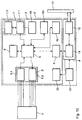
- Figure 1 shows an apparatus for performing the method according to the invention with an electromedical implant 1 using a telemetry device is provided and an external device 2, which consists of a handset 3 and a base station 4 exists.
- the handset 3 has a control device 5 and a first interface device 6, a mobile radio device 7, a second interface device 8 and a man-machine interface 9, each with the control device 5 are connected.
- the first interface device 6 consists of a telemetry transmitter / receiver unit, so that the handset 3 over a bidirectional telemetry line Can contact the implant.
- the receiver and the transmitter work in the UHF range at 403.55 MHz (range 402-405 MHz).
- the mobile radio device 7 can receive first data via the first interface device 6 were read from the implant in the form of SMS messages send and from a monitoring device or central storage device service center can be called.
- the handset is powered by Li-ion batteries in the power supply section 10 are housed.
- the base station 4 consists of a charger 11 for the batteries in the power supply part 10 and a modem 12 acting as a data transmission device for the fixed telecommunications network 13, from the handset 3 via one with the second interface device 8 cooperating third interface device 14 is addressed.
- the second and third interface devices 8 and 14 are designed as infrared interfaces (IrDA).
- the handset 3 is used for charging and data transmission over the fixed telecommunications network 13 inserted into the base station.
- the control device 5 is designed so that when connected to the fixed telecommunications network 13th via the second interface device 14 only after execution of a predetermined one Number of unsuccessful transmission attempts via the mobile radio device 7 Transmission of the first data to the monitoring device via the fixed telecommunications network 13 takes place.
- the base station 4 further comprises an additional antenna 15 which, when connected to the handset 3 is connected to the mobile radio device 7 and thus the transmission quality improved.
- Suitable ⁇ / 4 antennas are provided, which are designed as loop or helix antennas.
- the additional antenna is as Diversity antenna 15 executed.
- the handset has a fourth interface device 16, which is also called IrDA interface is formed.
- This fourth interface device 16 is used for the recording of external data or used for the service.
- the receiver and the transmitter of the transceiver 6 are in an IC integrated. Both parts of the circuit form a functional unit. As baud rate levels 4, 8, 16 and 32 kbps are provided.
- the software is in a flash ROM via the IrDA interface 16 downloadable.
- the storage capacity of the internal flash ROM is 128 KB, that of the integrated EEPROM 4 KByte and that of the static, external SRAM 64 Kbyte.
- the program memory size is therefore based on the capacity of the built-in Flash ROMs limited and cannot be expanded (Harvard structure).
- the external static SRAM is expandable.
- a 128 bit DES encryption method is used for the SMS transmission, which is based on a private-public key system.
- the encryption will implemented in software, i.e. no encryption IC is used.
- a watchdog circuit is provided that is in regular use Processor 5 checked distance and back to a safe status transferred if the program execution does not run correctly.
- the external device 2 carries out a self-test and reports the result via SMS to the service center, if an error in operation is detected, a request from Service center starts the self-test of external device 2 or the external device 2 reconnects after a power-on reset.
- the field strength information via SMS with the corresponding numbers of the current and adjoined cells and the Bit error rate is transmitted. Based on this location information is a location the external device 2 in emergencies in which the patient is unable to act, possible.
- the mobile radio device 7 comprises a mobile radio module 7.1 and a SIM card trained memory 7.1.
- the SIM card reader can be found under the cell phone module 7.1 are soldered directly into the circuit board.
- the user is the SIM card 7.1 not accessible.
- the SIM card 7.1 will be or will be in addition, the service center number (s) are permanently stored. Via SMS the number of the service center on the SIM card can be changed. The old Number is stored on the SIM card for security in another location held and used when the external device 2 with the new number none Can establish connection.
- the mobile radio module 7.1 uses the SIM card for the temporary storage of SMS messages.
- the power supply of the handset 3 is realized with Li-ion batteries. You can the handset 3 in the fully charged state for at least 20 hours (standby time + 16 SMS transmissions) without connection to base station 4. At When the handset 3 is switched on, the batteries are back in the base station after approx. 4 hours fully charged.
- the dimensions of the batteries apply at the end of their service life. It is therefore a 1000 mAh Li-ion battery provided.
- the handset 3 is inserted into the base station 4 for charging.
- the handset 3 is during the Charging in base station 4 fully functional.
- the voltage converter in the Base station are designed up to 40 V, so that a connection for charging from a Automotive network is possible.
- the control device 5 monitors the battery voltage and Power supply on the cell phone module 7.1.
- the second interface device 8 is to be designed according to the IrDA standard. She works bidirectionally and can transmit data in half-duplex mode. This Interface 8 is used only to operate the modem 12 in the base station used. The IR interface 8 of the handset 3 and the IR interface 14 of the Base station 4 are always ready to receive. The handset 3 exchanges with the Base station 4 data as soon as it is inserted into it. So that is the handset 3 in each case it is known whether a modem 12 is equipped in the base station 4.
- the modem 12 is integrated in the base station 4 and, if necessary, by the service technician equipable. The modem 12 can simply be snapped into the base station are and is then operated via an IrDA interface 14. The modem is 12 switchable to a software handshake, since the IrDA interfaces 8 and 14 only this type of "optical 2-wire transmission" is supported.
- the range of the fifth interface device, also called the IrDA interface is at least 0.4 m.
- the IrDA interfaces are as possible designed to save energy.
- the fifth interface device 16 is arranged such that it is operated by a device which is next to the external device 2, can be used when the handset 3 is inserted into the base station 4. It works bidirectionally and can operate in half duplex Transfer data.
- the transmission speed of the fifth Interface device 16 starts at 9600 baud and can then increase to 115 KBaud can be shifted up.
- a service technician can use this interface 16, for example e.g. a laptop with an IrDA interface can communicate with the handset 3.
- the external device works as a data logger, by reading data (e.g. as a blood sugar monitor), which is then also via SMS sent to the service center.
- the range of the IrDA interface 16 is at least 0.4m.
- the fifth interface device 16 is to be arranged so that the communication between base station 4 and handset 3 works safely, i.e. Influences the second interface device 8 by the fifth interface device 16 are excluded.
- the serial interface for both IrDA interfaces 8 and 16 and the interface are parallel to the mobile radio device 7, so that only one unit is operated at a time can be.
- the IrDA interfaces 8 and 16 are connected in parallel. Both Interfaces are always ready to receive, so that an external request at any time can be operated. The software then only has to determine at which IrDA interface the receive request is.
- the power supply 11 in the base station supplies the charger for the Li-ion batteries and provides the supply for the IrDA interface 14 and the modem 12. Das The charger comes with a controller suitable for Li-ion batteries and a monitoring circuit equipped. It is for a maximum charging current of 350mA designed.
- the power supply 11 is for a primary switchable AC voltage of 220 / 110V, 50 / 60Hz dimensioned, with a range of 100 to 240 V for the primary input voltage and a frequency range of 47-63 Hz is preferred. Protection class 2 is used for external device 2.
- the power supply in the base station 4 can also be replaced by a suitable plug-in power supply.
- telemetry units 6 are for communication with the implant 1 including a transmit / receive antenna for the Telemetry frequency and control electronics and a fourth interface device 17 installed in a separate housing.
- This separate housing has a mechanical and electrical interface for the battery compartment of a mobile phone on. That is, the battery pack of the mobile phone is removed and replaced whose the separate housing is used, so that there is a mechanically stable Unit of mobile phone and separate housing, which, if necessary, the previous outer contour of the mobile phone surpassed.
- the electrical connection between the mobile phone and the Telemetry unit manufactured in a separate housing (at least with regard to the Power supply via the connections of the battery pack).
- the separate housing has a battery compartment for power supply to the overall system in which the original battery pack of the mobile phone or one another suitable battery or a suitable battery pack can be inserted.
- This battery then serves to power the entire system from a mobile phone and telemetry unit and can be connected to the standard charging connections on Mobile phone can be charged.
- the interface integrated in the battery compartment requires one mechanical and electrical modification of the mobile phone.
- This interface is connected to the electronics of the mobile phone direct control of the mobile phone possible through the telemetry unit.
- the electronics of the mobile phone can be controlled by the permanently on standby or optionally time-controlled Telemetry unit can be put into operation automatically if necessary (event control).
- the base station 4 is equipped with a light emitting diode which lights up when that Handset 3 is plugged in and a charging current charges the batteries.
- the light emitting diode goes out when the handset 3 is removed or there is no more power from the handset 3 is recorded.
- the display of the light emitting diode is but inverted at least a second if over the built-in Modem 12 sends or receives a message.
- the base station 4 acknowledges inserting the handset 3 or removing the handset 3 a short tone of a buzzer.
- the handset 3 has a recessed on / off switch that is not inadvertently can be operated.
- the switch position is labeled so that you can see whether the handset 3 is switched on. This switch is necessary because the handset 3 switched off with the mobile radio device 7 in some surrounding areas must become. This is e.g. B. during a flight and in certain areas of Hospitals necessary.
- a button for the patient alarm is inserted into the handset 3.
- the button is like this interpret that it is safely protected against accidental incorrect operation.
- This The emergency button is therefore recessed.
- it can be Cover must be protected, which must first be opened to the patient alarm trigger, or the misuse protection is due to a time lock in the software executed, which only accepts the key function as valid when the Button is pressed longer (e.g. more than 3 s).
- the patient alarm is immediately over an SMS forwarded to the service center.
- the successfully triggered patient alarm is acknowledged acoustically by the buzzer.
- the button can then be released.
- the buzzer is always at the same time actuated with the light-emitting diode, so that even old people receive this receipt from the external device.
- the alarm is not cleared until the Service center acknowledges the patient alarm via SMS, thus ensuring that the alarm has arrived at the service center.
- a blinking LED indicates the low battery state is shown.
- the handset 3 is still minimal about 2 hours of power reserve. Since the handset 3 is not always for the patient is visible, the buzzer indicates the occurrence of the low battery state by means of a short alarm on. The buzzer should trigger an alarm every 5 minutes, to remind the patient to recharge the battery. After recharging of the battery becomes the acoustic alarm function of the low battery state in focus again. The buzzer must be at a frequency of approximately 2 kHz and work underneath and be correspondingly loud, so that older patients too Can hear the alarm sound safely.
- the LED and the buzzer for the Acknowledgment of the patient alarm used.
- the successful implementation of the Patient alarms have a higher priority than the low battery display.
- the Low-battery display is only shown again when the service center receives the Patient alarm has acknowledged. Should be a disturbance of the environment by the buzzer are prevented, the handset 3 must be switched off.
- the external device 2 is supplied with a SIM card, which is stored in the phone number contains the number of a service center by default. It can several service centers are operated. This makes particular sense if thereby avoiding that the SMS message is sent across borders got to. A procedure is therefore provided for how the patient devices Assigned to service centers and also transferred to other service centers can be made without a service technician having to drive to the patient device, to change it.
- the patient registers with a service center. This makes the service center the address of the customer is known and it can be decided which one Service center takes over the service. If the customer switches on his external device, then it registers with the preset service center by immediately sends an SMS to them. The service center can now by return a special SMS to transmit the number that will be used in the future should. The patient device is subsequently assigned to another service center.
- the first number is saved on the SIM card for security held and also used when the external device 2 with the new number none Can establish connection. This ensures that the contact always remains.
- the service center databases are identical to one another so that it is always clear which implant or external device is softer Service center is operated. Appropriate fields must be provided in the database.
- Number management (writing and reading numbers to and from the SIM card) must be taken over by the central processor of the external device. Only one additional (second) number can be accepted in the company. This is used if the contact to the "new service center" is successful can be manufactured. If this is not the case, the "old number will be restored used ". If the external device is transferred to another service center again, the second number is overwritten so that the process is always like this that the second number is tried first and one or more Failed attempt (s) the first number is used.
- the advantage of this procedure lies that full flexibility is possible, but the secure number is saved remains so that a complete breakdown of the connection is safely avoided becomes.
- LiFo memory for a maximum memory depth (e.g. ten numbers) organized. Gives the previously responsible service center one new number, it is used as the most current number. But arise with this new number transmission problems, the next older one Number used until it is the turn of the preset number. Is the memory is occupied, e.g. with 9 numbers and the preset number the oldest, i.e. the number closest to the preset, is deleted.
- the advantage of this method is its high redundancy, since it can be assumed that a connection is securely established with one of the stored service centers is coming.
- the disadvantage is that many service centers may have data from receive an external device, which is then put together and shared can be evaluated.
- the call number memory can used in the SIM card for these numbers become.
- the organization can be based on the management of mobile phone numbers shape.
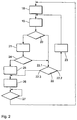
- FIG. 2 shows a flow chart of the method for data transmission according to the invention, that for data transmission between the implant 1 and the external Device 2 can be used.
- the first transmitter / receiver unit of the implant 1 comprises a transmitter (VHF) and a receiver (VHF or LF).
- the second transmitter / receiver unit of the external device 2 comprises a receiver (VHF) and a transmitter (VHF or LF). Both communicate bidirectionally via a radio link.
- the baud rate implant external device is 4, 8 or 16 kbit / s.
- External device for the route - Pacemaker uses the same baud rate again for VHF transmission with LF transmission approx. 10 bit / s.
- the trigger signal for data transmission is always from the first transmitter / receiver unit of the implant 1, for which purpose in a step 18 Transmitter / receiver unit is switched on.
- the transmission of the first data then takes place the implant 1 to the external device 2.
- a string is transmitted which consists of 17 Byte exists. These are 1 byte synchronization, 4 byte identification, 1 byte consecutive number of the transfer, 1 byte length of the transfer string, 8 Byte data, 2 byte security (CRC).
- CRC 2 byte security
- step 20 there is then a plausibility check of the first sent Data from the external device.
- the CRC bits related to the string sent or a check to see if the Synchronization bits have the previously known values. Furthermore can checked whether the string length matches the transmitted string length and / or whether the serial number of the transmission is correct.
- a first receipt is sent to the implant 1 sent, the first acknowledgment a first control information for control contains the readiness for reception of the first transmitter / receiver unit.
- a control data record sent by the Implant 1 is checked. There are two options:
- the previously sent first data record is completely sent to the Implant 1 sent back, which is then the one sent with the one received Compares record. Then 187 bits would be sent back.
- step 20 If the external device detects in step 20 that the data is not plausible, if it was determined in a step 22 that a predetermined number retransmissions is not yet exceeded, valid in a step 23 Data requested from the pacemaker.
- step 21 the string or the CRC bits in step 21 are sent to the implant for control in step 24. If the test is successful, the implant sends a second one in step 25 Acknowledgment to the external device 2. The implant 1 then provides all in step 26 Send and receive activities until one after the first time interval new record for the shipment is pending. The first time interval expires checked in step.
- the patient device After receiving the second receipt, the patient device is now verified forward the first data to the service center.
- the first record is as marked valid and the service center knows that this data with a very high Probability are correct.
- the external device keeps this first data until the implant delivers a new, correctly verified data set.
- step 24 If the control in step 24 is negative, i.e. the control data are not identical to the output data, the first data record is sent again. The implant then tries again after a specified period of time. The external device 2 incorrectly informs the service center of the number transmitted data packets.
- the implant sends the second receipt to the external device an error occurs (e.g. different implant number or acknowledgment code is not true) the first data will still be sent to the service center via SMS sent, but it is also reported by the external device 2 that the second Receipt of implant 1 could not be validly transferred.
- an error e.g. different implant number or acknowledgment code is not true
- the implant 1 after sending the second receipt after a precisely defined third time interval Receipt goes and a new request from the external device 2 answered.
- the second receipt or the first data record can be sent again.
- the External device 2 then has either the first data record or the second receipt duplicate and can now decide whether the first record is valid can be accepted.
- a first acknowledgment is sent instead of the string or the CRC data, requesting a new shipment. This first receipt could go out again 88 bits exist.
- the implant 1 can immediately after checking that it is addressed, start with the new broadcast without first having received Data must be evaluated.
- the send / receive cycles can be repeated several times. But it has to go In order to save energy, care should be taken that after a certain Number of shipments is canceled to the energy storage of the implant not to discharge unnecessarily.
- the external device should then still send the data to the Send the service center, but the data must be marked as not verified.
- the data is held in the external device 2 until a new data record is dated Implant is sent.
- the last valid data record should be in the external Device that the service center can then query. With several Implants that work together with the external device 2 are each to keep the last records of each implant in the external device 2.
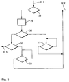
- Figure 3 represents step 22 from FIG. 2 with the input 22.1 and the outputs 22.2 and 22.3 in detail.
- the program is tried a second time as close as possible transfer successfully. It is examined in step 28 whether a counter Z has not yet exceeded a predetermined first value, here 2.
- the counter Z represents the number of transmission attempts carried out. He is set to zero in step 18 and by 1 with each iteration of step 19 elevated. If the first value has not yet been exceeded, output 22.2 immediately initiated a new transmission.
- step 29 was set to zero and it was examined in step 30 whether the counter Z unites has not yet exceeded the predetermined second value, here 3, through the holding pattern 31
- the receiver of the external device 2 is in certain implementations of the method ready to receive data from the implant at any time.
- the implant sends a message to the external partner at any time. If more than one message is to be sent, they will be sent one after the other sent. The receipts are analyzed to determine whether the external Remote station wants to send 2 more data and it is then automatically in the Protocol for the transmission of data in the opposite direction (as described above) continued.
- a reduction in energy consumption is also in the external device 2 achieved.
- the implant and the external device are synchronized by negotiation on time slices, which defines periodic times in which the Receiver of the external device is active.
- the implant 1 may then only send within these time slices to be received.
- the above Instructions are modified accordingly, so that the Implant 1 can only send within the time slices and no longer to any Times.
- the time slices can be used in the normal bidirectional manner described above Communication in the duration of the active as well as the passive phase as well as the synchronization time can be changed. Be about one no more consignments are received from the implant for a certain period of time the active time slice is gradually extended to one at the expense of the passive To drift apart the synchronicity. In extreme cases, the recipient is permanently active in the external device. This is also the reset state when switching on.
- FIG. 4 shows a block diagram of a variant of a patient monitoring system using the present invention.
- Data is transferred between the implant 1 and the external one Device 2 from Figure 1, the implant 1 is carried by a patient 33.
- the data read out are transmitted from the external device 2 via a mobile radio link 34 of a cellular network to a cellular station 35 of the cellular network transmitted and from there also via a mobile radio link 36 or alternatively sent via a landline connection 37 to a service center 38, which as central storage device and monitoring device is used.
- the data are sent as SMS.
- An SMS goes to the service center 38, it sends an acknowledgment SMS back to the external device 2.
- For the microprocessors in external devices with their real-time clock is only that relative time available. The time in implant 1 is not adjusted and after one half year to within +/- 0.5 hours, so that it cannot be used. If the battery of the mobile external device is empty or by the service technician is removed, it can also happen that the real-time clock totally loses time. However, the external device needs the current time for the SMS message that is sent to the service center to document when the event was received by the pacemaker.
- the time signature (SMS header) of the Acknowledgment SMS is used, which contains the date and time.
- this acknowledgment SMS comes within e.g. a minute back it can external device 2 set the absolute time after the header of the receipt, because it is guaranteed that both SMS were under way for less than a minute. Is It may have been a long time between the SMS sent and the receipt The SMS header of the receipt cannot be evaluated because it cannot be determined whether the original broadcast or the receipt was delayed. The Experience has shown that the time for an SMS transmission is less than 10s, so that one can use the above procedure well.
- Such a Service is usually provided by different providers for the public telephone network made available.
- the central storage unit 38 is equipped with a fully automatic database.
- the medical data is automatically in via TCP / IP connection the database computer read in, there they are in according to their content entered the correct tables.
- the database stores this data and generates correspondingly predefined ones Rules information for the doctor and the system administrator and passes it on Fax, email, internal and external computer connection to the target devices 39. For reasons of cost and clarity, the information provided is stored in the database for later collective queries.
- the access options to the data are regulated by complex rights distribution (e.g. reading, writing, changing, deleting, etc.) for different User groups data administrator, clinic, doctor.
- Priority-controlled triggers in the database and a coupled expert system make it possible to react specifically to medical facts: It adapted content is sent by fax, email, telephone (to a doctor or emergency call center) and computer connection with doctor / clinic. The doctor can do one Request a summary or lost report regarding the patient again. He receives medical information in a few minutes even during the Examination and summarized information for the next follow-up appointment.
- the transmission medium and the destination addresses depend on the time of triggering configurable. This allows the attending physician 40 to one of desired information about the state of health of his Receive patient 33, and patient 33 may be faster than usual in an emergency get medical attention. This emergency is measured both objectively medical data, as well as triggered by pressing a button on the patient device 2. He takes top priority over the other events.
- FIG. 5 shows a block diagram of a variant of a patient monitoring and aftercare system using the present invention.
- the patient 33 with the implant 1 and the external device is located here 2 for aftercare examination in a query area 41 of a aftercare facility. It is triggered by the external device when entering the Interrogation area 41 cooperating trigger device automatically Querying the first data from the implant 1 before the follow-up examination performed by the doctor 40.
- the first data is transferred by means of the long-range telemetry connection between the implant 1 and the external device 2.
- the result of the query is processed in accordance with FIG. 4 described route via the service center 38 to the target device 39, from which it is the doctor 40 is issued for his information. At the same time further patient-related data from the database of the service center 38 output so that the doctor 40 can get a comprehensive picture.
- the individual examination of the doctor (where he may only have a few comparative data from the past) is shown by an overall picture over time added since the last visit to the doctor.
- the doctor gets an image of several Weeks or months, which is much more meaningful than the current one Investigation.
- the patient's lifestyle is well mapped, where against the appointment with the doctor an exceptional situation from can represent familiar life (trip to the clinic or doctor, climbing stairs, Stress in traffic etc.).
- the doctor can also do the actual examination (e.g. during stress tests) Request a report from the service center 38 immediately, which will then appear after a few Minutes is delivered. This allows parameter changes to be made using the Programmers have been hired, checked immediately and optimized if necessary.
- Figure 6 shows a variant of the embodiment of Figure 5, in the query area 41 of the aftercare device, an external device 2 'is permanently installed.
- the query is triggered as soon as the patient 33 with the implant 1 for one certain period of time is in the query range of the external device 2 '.
- the result of the query is processed directly from the external source Device 2 'to the target device 39, from which it to the doctor 40 for his information is issued.
- other patient-related connections are made via the connection 43 Data from the database of the service center 38 queried and on Target device 39 output, so that the doctor 40 also here a comprehensive picture can make.
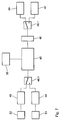
- FIG. 7 shows a block diagram of a telemetry device of an electromedical device Implant using the present invention.
- the telemetry device has a near field transmitter 44, an associated therewith Telemetry unit 45 and an antenna interface device connected to the telemetry unit 45 46, via which the first antenna 47 with the near-field transmitter / receiver unit connected is.
- the other necessary system components for a telemetry device such as a buffer, sequence control, Coding and decoding, drivers with threshold detectors are included in the Telemetry unit 45 integrated.
- the Far field telemetry equipment operates at substantially the same effective data rate how the near field telemetry device operated.
- the near field telemetry device and the far field telemetry device have separate energy storage 51 and 52.
- Figure 8 shows the transmitter / receiver unit of an embodiment of the implant 1, in the energy stores 56 and 57 separate for the transmitter 54 and the receiver 55 are provided. These are separate buffer capacities 56 and 57. These capacities 56 and 57 only have to match those for the respective process necessary voltage can be charged. The energy consumption of one process does not affect the energy supply for the other process. The operations can thus follow each other immediately, what a bidirectional communication protocol is an advantage.
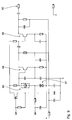
- FIG. 9 shows a circuit diagram of a transmitter according to the invention of the first transmitter / receiver unit a variant of the implant 1 from FIG. 1.
- a stable frequency-modulated transmitter is with two bipolar transistors 58, 59 can be realized.
- the first transistor 58 in a Colpitts or Clapp circuit with a SAW resonator 60 a SAW stabilized oscillator forms and the second transistor 59 serves as a buffer stage and antenna driver.
- the transistors 58, 59 are at maximum amplification with the lowest collector current designed.
- a capacitance diode 61 in series with the SAW resonator 60 the frequency can be modulated.
- a simple wire loop or an open wire (wire antenna) can be used as the antenna. serve in the contour of the head of the implant. Overall, this is at 400 MHz a power consumption of less than 1 mA with a range of several Meters possible.
- the circuit can be made directly from a high impedance Battery of the implant 1 fed buffer capacity or a low-resistance Battery are supplied. A charge pump is not required.
- FIG. 10 shows a further exemplary embodiment of a device according to the invention, which corresponds essentially to that of Figure 1, which is why here only the differences should be dealt with.
- Applications can be the remote monitoring of plants, e.g. of Filling levels of drinks or vending machines, the connection to the building services, e.g. Control and monitoring of air conditioning or heating, the coupling on alarm systems or broken glass alarm systems, e.g. Intrusion notification via mobile radio, coupling to measuring systems, e.g. Weather stations or level meters Rivers, the coupling to systems for monitoring and influencing traffic, e.g. Sign bridges etc. It can also be used as a listening device or as a mobile phone can be used with special digital functions.
- the differences from the embodiment from FIG. 1 essentially concern this Handset 3 'of the external device 2'.
- the first interface device comprises 4 potential-free inputs 6.1 via optocouplers and 4 potential-free outputs 6.2. Thanks to the potential separation of the inputs and outputs 6.1 and 6.2 is suitable the external device 2 'for the monitoring and control of digital states.
- the receiving and transmitting part 6 from FIG. 1 is omitted; released serial interface 63 (RS 232) via a 9-pin connector led out.
- a software handshake with three lines is sufficient for the RS 232 (RXD, TXD, OND).
- the transmission rate is also limited to 9600 baud.
- the serial interface 63 is not designed to be potential-free.
- the connector of the mobile radio module 7.1 can be connected to a further connector 64 Microphone, a loudspeaker and optionally a buzzer (6 lines), so that for other areas of application a hearing / speaking combination and a Buzzer can be added.
- Inputs 6.1 are in range 1 at -3V to 1.5V L level, 3.5 to 8V H level and 10 mA input current; in area 2 at -3V to 8V L level, 18V to 30V H level and 10 mA input current.
- the status is recognized via an LED display at a maximum switching frequency of 100 Hz square wave and a separation voltage of 2.5kV.
- the outputs have 15 to 30V DC separate voltage supply, one Load current of 200mA, short-circuit protection, protection against thermal overload and a separation voltage of 2.5kV. Electrical isolation is via optocouplers, the power switching function is implemented via MOS-FETs.
Landscapes
- Health & Medical Sciences (AREA)
- Animal Behavior & Ethology (AREA)
- Public Health (AREA)
- Nuclear Medicine, Radiotherapy & Molecular Imaging (AREA)
- Radiology & Medical Imaging (AREA)
- Life Sciences & Earth Sciences (AREA)
- Engineering & Computer Science (AREA)
- General Health & Medical Sciences (AREA)
- Biomedical Technology (AREA)
- Veterinary Medicine (AREA)
- Mobile Radio Communication Systems (AREA)
- Electrotherapy Devices (AREA)
- Arrangements For Transmission Of Measured Signals (AREA)
- Measuring And Recording Apparatus For Diagnosis (AREA)
- Near-Field Transmission Systems (AREA)
Applications Claiming Priority (2)
| Application Number | Priority Date | Filing Date | Title |
|---|---|---|---|
| DE19930263 | 1999-06-25 | ||
| DE19930263A DE19930263A1 (de) | 1999-06-25 | 1999-06-25 | Verfahren und Vorrichtung zur Datenübertragung zwischen einem elektromedizinischen Implantat und einem externen Gerät |
Publications (3)
| Publication Number | Publication Date |
|---|---|
| EP1062980A2 true EP1062980A2 (fr) | 2000-12-27 |
| EP1062980A3 EP1062980A3 (fr) | 2004-01-21 |
| EP1062980B1 EP1062980B1 (fr) | 2006-03-01 |
Family
ID=7913251
Family Applications (1)
| Application Number | Title | Priority Date | Filing Date |
|---|---|---|---|
| EP00250197A Expired - Lifetime EP1062980B1 (fr) | 1999-06-25 | 2000-06-23 | Procédé et dispositif de transmission de données entre un implant électromédical et un appareil externe |
Country Status (4)
| Country | Link |
|---|---|
| US (1) | US6893395B1 (fr) |
| EP (1) | EP1062980B1 (fr) |
| AT (1) | ATE318637T1 (fr) |
| DE (2) | DE19930263A1 (fr) |
Cited By (1)
| Publication number | Priority date | Publication date | Assignee | Title |
|---|---|---|---|---|
| CN1692881B (zh) * | 2004-05-07 | 2010-09-01 | 精工电子有限公司 | 有机体信息测量装置 |
Families Citing this family (77)
| Publication number | Priority date | Publication date | Assignee | Title |
|---|---|---|---|---|
| US9042988B2 (en) | 1998-08-05 | 2015-05-26 | Cyberonics, Inc. | Closed-loop vagus nerve stimulation |
| US7747325B2 (en) | 1998-08-05 | 2010-06-29 | Neurovista Corporation | Systems and methods for monitoring a patient's neurological disease state |
| US7209787B2 (en) | 1998-08-05 | 2007-04-24 | Bioneuronics Corporation | Apparatus and method for closed-loop intracranial stimulation for optimal control of neurological disease |
| US9375573B2 (en) * | 1998-08-05 | 2016-06-28 | Cyberonics, Inc. | Systems and methods for monitoring a patient's neurological disease state |
| US8762065B2 (en) | 1998-08-05 | 2014-06-24 | Cyberonics, Inc. | Closed-loop feedback-driven neuromodulation |
| US9415222B2 (en) | 1998-08-05 | 2016-08-16 | Cyberonics, Inc. | Monitoring an epilepsy disease state with a supervisory module |
| US9113801B2 (en) * | 1998-08-05 | 2015-08-25 | Cyberonics, Inc. | Methods and systems for continuous EEG monitoring |
| MXPA03000516A (es) * | 2000-07-21 | 2004-05-31 | Itron Inc | Sistema de lectura de medicion de espectro de propagacion utilizando salto de frecuencia de alta potencia/baja velocidad. |
| DE10317131A1 (de) * | 2003-04-14 | 2004-10-28 | Siemens Ag | Verfahren zur Datenübertragung von sicherheitsrelevanten Informationen |
| US7330763B1 (en) * | 2003-04-30 | 2008-02-12 | Advanced Neuromodulation Systems, Inc. | Method for securing the operating system in a handheld medical device and apparatus |
| DE10351782B4 (de) * | 2003-11-06 | 2007-03-29 | Siemens Ag | Medizinisches System |
| DE102004043210A1 (de) * | 2004-09-03 | 2006-03-09 | Biotronik Vi Patent Ag | Sende- und Empfangsgerät |
| WO2006022993A2 (fr) * | 2004-06-10 | 2006-03-02 | Ndi Medical, Llc | Generateur d'impulsions implantable assurant une stimulation fonctionnelle et/ou therapeutique des muscles et/ou des nerfs et/ou des tissus du systeme nerveux central |
| US9205255B2 (en) | 2004-06-10 | 2015-12-08 | Medtronic Urinary Solutions, Inc. | Implantable pulse generator systems and methods for providing functional and/or therapeutic stimulation of muscles and/or nerves and/or central nervous system tissue |
| US9308382B2 (en) | 2004-06-10 | 2016-04-12 | Medtronic Urinary Solutions, Inc. | Implantable pulse generator systems and methods for providing functional and/or therapeutic stimulation of muscles and/or nerves and/or central nervous system tissue |
| DE102004043212A1 (de) * | 2004-09-03 | 2006-03-09 | Biotronik Vi Patent Ag | Kommunikationsmodul und Verfahren zu dessen Betrieb |
| US7545272B2 (en) | 2005-02-08 | 2009-06-09 | Therasense, Inc. | RF tag on test strips, test strip vials and boxes |
| ATE431683T1 (de) * | 2005-04-06 | 2009-05-15 | Telit Comm S P A | Teilnehmeridentitätsmodul und mobilkommunikationseinrichtung mit einem solchen modul |
| US9168383B2 (en) | 2005-10-14 | 2015-10-27 | Pacesetter, Inc. | Leadless cardiac pacemaker with conducted communication |
| US8010209B2 (en) | 2005-10-14 | 2011-08-30 | Nanostim, Inc. | Delivery system for implantable biostimulator |
| US8868172B2 (en) | 2005-12-28 | 2014-10-21 | Cyberonics, Inc. | Methods and systems for recommending an appropriate action to a patient for managing epilepsy and other neurological disorders |
| US8725243B2 (en) | 2005-12-28 | 2014-05-13 | Cyberonics, Inc. | Methods and systems for recommending an appropriate pharmacological treatment to a patient for managing epilepsy and other neurological disorders |
| USRE49527E1 (en) * | 2006-02-10 | 2023-05-16 | Cochlear Limited | Recognition of implantable medical device |
| DE102006019606A1 (de) * | 2006-04-25 | 2007-10-31 | Biotronik Crm Patent Ag | Implantierbares batteriebetriebenes Elektrostimulationsgerät |
| US9480846B2 (en) * | 2006-05-17 | 2016-11-01 | Medtronic Urinary Solutions, Inc. | Systems and methods for patient control of stimulation systems |
| EP2034885A4 (fr) | 2006-06-23 | 2010-12-01 | Neurovista Corp | Systeme et procede de surveillance tres peu invasifs |
| US8295934B2 (en) | 2006-11-14 | 2012-10-23 | Neurovista Corporation | Systems and methods of reducing artifact in neurological stimulation systems |
| DE102007001705A1 (de) | 2007-01-11 | 2008-07-17 | Biotronik Crm Patent Ag | Patientengerät für die drahtlose Datenkommunikation mit einem Implantat |
| WO2008092133A2 (fr) | 2007-01-25 | 2008-07-31 | Neurovista Corporation | Procédés et systèmes permettant de mesurer la prédisposition d'une personne à avoir une crise |
| EP2126785A2 (fr) * | 2007-01-25 | 2009-12-02 | NeuroVista Corporation | Systèmes et procédés d'identification d'un état contre-critique chez un sujet |
| US8036736B2 (en) | 2007-03-21 | 2011-10-11 | Neuro Vista Corporation | Implantable systems and methods for identifying a contra-ictal condition in a subject |
| DE102007018982A1 (de) | 2007-04-21 | 2008-10-23 | Biotronik Crm Patent Ag | Eine Follow-Up Untersuchung unterstützende Therapieeinheit sowie Therapiesystem |
| US8934984B2 (en) | 2007-05-31 | 2015-01-13 | Cochlear Limited | Behind-the-ear (BTE) prosthetic device with antenna |
| US8271082B2 (en) | 2007-06-07 | 2012-09-18 | Zoll Medical Corporation | Medical device configured to test for user responsiveness |
| US9788744B2 (en) | 2007-07-27 | 2017-10-17 | Cyberonics, Inc. | Systems for monitoring brain activity and patient advisory device |
| US9848058B2 (en) | 2007-08-31 | 2017-12-19 | Cardiac Pacemakers, Inc. | Medical data transport over wireless life critical network employing dynamic communication link mapping |
| US7978062B2 (en) | 2007-08-31 | 2011-07-12 | Cardiac Pacemakers, Inc. | Medical data transport over wireless life critical network |
| US20090171168A1 (en) | 2007-12-28 | 2009-07-02 | Leyde Kent W | Systems and Method for Recording Clinical Manifestations of a Seizure |
| US9259591B2 (en) | 2007-12-28 | 2016-02-16 | Cyberonics, Inc. | Housing for an implantable medical device |
| US20090226802A1 (en) * | 2008-01-31 | 2009-09-10 | Night Operations Systems | Connector for battery pack of lighting system |
| US7917226B2 (en) * | 2008-04-23 | 2011-03-29 | Enteromedics Inc. | Antenna arrangements for implantable therapy device |
| CN102204122B (zh) * | 2008-08-28 | 2014-12-10 | 艾森斯公司 | 用于无线设备之间通信的方法 |
| DE102008058264A1 (de) * | 2008-11-19 | 2010-07-08 | IAD Gesellschaft für Informatik, Automatisierung und Datenverarbeitung mbH | Messgerät, insbesondere Enegiezähler und Verfahren zur Erkennung von Manipulationen |
| US8849390B2 (en) | 2008-12-29 | 2014-09-30 | Cyberonics, Inc. | Processing for multi-channel signals |
| US8588933B2 (en) | 2009-01-09 | 2013-11-19 | Cyberonics, Inc. | Medical lead termination sleeve for implantable medical devices |
| US8527068B2 (en) | 2009-02-02 | 2013-09-03 | Nanostim, Inc. | Leadless cardiac pacemaker with secondary fixation capability |
| US8319631B2 (en) | 2009-03-04 | 2012-11-27 | Cardiac Pacemakers, Inc. | Modular patient portable communicator for use in life critical network |
| US8812841B2 (en) | 2009-03-04 | 2014-08-19 | Cardiac Pacemakers, Inc. | Communications hub for use in life critical network |
| US8786624B2 (en) | 2009-06-02 | 2014-07-22 | Cyberonics, Inc. | Processing for multi-channel signals |
| US8700173B2 (en) | 2009-10-27 | 2014-04-15 | St. Jude Medical Ab | Implantable medical device power saving communication |
| US8700153B2 (en) | 2009-12-08 | 2014-04-15 | St. Jude Medical Ab | Cardiac stimulating device |
| US9643019B2 (en) | 2010-02-12 | 2017-05-09 | Cyberonics, Inc. | Neurological monitoring and alerts |
| EP2627403A4 (fr) | 2010-10-12 | 2014-03-26 | Nanostim Inc | Capteur de température pour stimulateur cardiaque sans fil |
| US9060692B2 (en) | 2010-10-12 | 2015-06-23 | Pacesetter, Inc. | Temperature sensor for a leadless cardiac pacemaker |
| US9020611B2 (en) | 2010-10-13 | 2015-04-28 | Pacesetter, Inc. | Leadless cardiac pacemaker with anti-unscrewing feature |
| EP2651494B1 (fr) | 2010-12-13 | 2017-02-15 | Pacesetter, Inc. | Cathéter pour implantation |
| US9126032B2 (en) | 2010-12-13 | 2015-09-08 | Pacesetter, Inc. | Pacemaker retrieval systems and methods |
| CN103328040B (zh) | 2010-12-20 | 2016-09-14 | 内诺斯蒂姆股份有限公司 | 具有径向固定机构的无导线起搏器 |
| US10451897B2 (en) | 2011-03-18 | 2019-10-22 | Johnson & Johnson Vision Care, Inc. | Components with multiple energization elements for biomedical devices |
| US9812730B2 (en) | 2011-08-02 | 2017-11-07 | Johnson & Johnson Vision Care, Inc. | Biocompatible wire battery |
| WO2013067496A2 (fr) | 2011-11-04 | 2013-05-10 | Nanostim, Inc. | Stimulateur cardiaque sans dérivation ayant une batterie intégrale et des soudures redondantes |
| US9136939B2 (en) * | 2011-12-29 | 2015-09-15 | Roche Diabetes Care, Inc. | Graphical user interface pertaining to a bolus calculator residing on a handheld diabetes management device |
| US8857983B2 (en) | 2012-01-26 | 2014-10-14 | Johnson & Johnson Vision Care, Inc. | Ophthalmic lens assembly having an integrated antenna structure |
| US9002466B2 (en) | 2012-04-09 | 2015-04-07 | Greatbatch Ltd. | Diversity antennas for neurostimulator programming devices |
| US9802054B2 (en) | 2012-08-01 | 2017-10-31 | Pacesetter, Inc. | Biostimulator circuit with flying cell |
| US10361405B2 (en) | 2014-08-21 | 2019-07-23 | Johnson & Johnson Vision Care, Inc. | Biomedical energization elements with polymer electrolytes |
| US10361404B2 (en) | 2014-08-21 | 2019-07-23 | Johnson & Johnson Vision Care, Inc. | Anodes for use in biocompatible energization elements |
| US9941547B2 (en) | 2014-08-21 | 2018-04-10 | Johnson & Johnson Vision Care, Inc. | Biomedical energization elements with polymer electrolytes and cavity structures |
| US9715130B2 (en) | 2014-08-21 | 2017-07-25 | Johnson & Johnson Vision Care, Inc. | Methods and apparatus to form separators for biocompatible energization elements for biomedical devices |
| US9793536B2 (en) | 2014-08-21 | 2017-10-17 | Johnson & Johnson Vision Care, Inc. | Pellet form cathode for use in a biocompatible battery |
| US9599842B2 (en) | 2014-08-21 | 2017-03-21 | Johnson & Johnson Vision Care, Inc. | Device and methods for sealing and encapsulation for biocompatible energization elements |
| US9383593B2 (en) | 2014-08-21 | 2016-07-05 | Johnson & Johnson Vision Care, Inc. | Methods to form biocompatible energization elements for biomedical devices comprising laminates and placed separators |
| US10381687B2 (en) | 2014-08-21 | 2019-08-13 | Johnson & Johnson Vision Care, Inc. | Methods of forming biocompatible rechargable energization elements for biomedical devices |
| US10627651B2 (en) | 2014-08-21 | 2020-04-21 | Johnson & Johnson Vision Care, Inc. | Methods and apparatus to form biocompatible energization primary elements for biomedical devices with electroless sealing layers |
| US10345620B2 (en) | 2016-02-18 | 2019-07-09 | Johnson & Johnson Vision Care, Inc. | Methods and apparatus to form biocompatible energization elements incorporating fuel cells for biomedical devices |
| EP3352030B1 (fr) * | 2017-01-24 | 2019-11-20 | Siemens Healthcare GmbH | Unité d'extension portative pour l'utilisation d'un appareil médico-technique et procédé de fonctionnement d'un appareil médico-technique |
| US11568984B2 (en) | 2018-09-28 | 2023-01-31 | Zoll Medical Corporation | Systems and methods for device inventory management and tracking |
Citations (1)
| Publication number | Priority date | Publication date | Assignee | Title |
|---|---|---|---|---|
| US5720770A (en) | 1995-10-06 | 1998-02-24 | Pacesetter, Inc. | Cardiac stimulation system with enhanced communication and control capability |
Family Cites Families (38)
| Publication number | Priority date | Publication date | Assignee | Title |
|---|---|---|---|---|
| US4172459A (en) | 1977-10-17 | 1979-10-30 | Medtronic, Inc. | Cardiac monitoring apparatus and monitor |
| FR2491659B1 (fr) | 1980-10-07 | 1986-04-04 | Medtronic Inc | Dispositif de telemesure pour un stimulateur implantable |
| US4531527A (en) | 1982-04-23 | 1985-07-30 | Survival Technology, Inc. | Ambulatory monitoring system with real time analysis and telephone transmission |
| DE3220930A1 (de) * | 1982-06-03 | 1983-12-08 | Siemens AG, 1000 Berlin und 8000 München | Zweiwegkommunikationssystem zwischen einem implantierbaren elektrischen stimulator und einer externen kontrolleinheit |
| US4625730A (en) * | 1985-04-09 | 1986-12-02 | The Johns Hopkins University | Patient ECG recording control for an automatic implantable defibrillator |
| US4741341A (en) | 1986-03-12 | 1988-05-03 | Siemens-Pacesetter, Inc. | Protection circuit and method for implanted ECG telemetry circuits |
| US4809697A (en) | 1987-10-14 | 1989-03-07 | Siemens-Pacesetter, Inc. | Interactive programming and diagnostic system for use with implantable pacemaker |
| EP0344770A1 (fr) | 1988-06-01 | 1989-12-06 | State Of Israel-Ministry Of Agriculture | Appareil de télémetrie sans fils destiné à la mesure de l'impédance de tissus vivants |
| DE3831809A1 (de) | 1988-09-19 | 1990-03-22 | Funke Hermann | Zur mindestens teilweisen implantation im lebenden koerper bestimmtes geraet |
| DE3936547A1 (de) | 1989-11-02 | 1991-05-08 | Siemens Ag | Anordnung zur telemetrischen kommunikation zwischen zwei geraeten mittels eines magnetischen nahfeldes |
| US5354319A (en) * | 1990-01-22 | 1994-10-11 | Medtronic, Inc. | Telemetry system for an implantable medical device |
| US5127404A (en) * | 1990-01-22 | 1992-07-07 | Medtronic, Inc. | Telemetry format for implanted medical device |
| US5187657A (en) | 1990-04-05 | 1993-02-16 | Hewlett-Packard Company | Cardiac analyzer with rem sleep detection |
| US5197480A (en) | 1990-06-08 | 1993-03-30 | Vitatron Medical, B.V. | System and method for monitoring heart transplant rejection |
| US5113869A (en) * | 1990-08-21 | 1992-05-19 | Telectronics Pacing Systems, Inc. | Implantable ambulatory electrocardiogram monitor |
| US5139028A (en) | 1990-10-26 | 1992-08-18 | Telectronics Pacing Systems, Inc. | Heart rejection monitoring apparatus and method |
| DE4100568A1 (de) | 1991-01-11 | 1992-07-16 | Fehling Guido | Vorrichtung zur ueberwachung eines patienten auf abstossungsreaktionen eines implantierten organs |
| US5191891A (en) | 1991-09-10 | 1993-03-09 | Ralin, Inc. | Portable ECG monitor/recorder |
| EP0537936A1 (fr) | 1991-10-17 | 1993-04-21 | Physio-Control Corporation | Transmission facsimilée pour les données électrocardiographiques |
| US5353793A (en) | 1991-11-25 | 1994-10-11 | Oishi-Kogyo Company | Sensor apparatus |
| US5313953A (en) | 1992-01-14 | 1994-05-24 | Incontrol, Inc. | Implantable cardiac patient monitor |
| US5522396A (en) | 1992-05-12 | 1996-06-04 | Cardiac Telecom Corporation | Method and system for monitoring the heart of a patient |
| US5342408A (en) | 1993-01-07 | 1994-08-30 | Incontrol, Inc. | Telemetry system for an implantable cardiac device |
| US5411536A (en) * | 1993-06-03 | 1995-05-02 | Intermedics, Inc. | Method and apparatus for communicating data between medical devices to improve detectability of errors |
| US5411031A (en) | 1993-11-24 | 1995-05-02 | Incontrol, Inc. | Implantable cardiac patient monitor |
| US5413594A (en) | 1993-12-09 | 1995-05-09 | Ventritex, Inc. | Method and apparatus for interrogating an implanted cardiac device |
| DE4341903A1 (de) | 1993-12-09 | 1995-06-14 | Josef Prof Dr Rer Nat Binder | Implantierbares telemetrisches Endosystem |
| US5729203A (en) | 1994-06-28 | 1998-03-17 | Colin Corporation | Emergency call system |
| US5626630A (en) | 1994-10-13 | 1997-05-06 | Ael Industries, Inc. | Medical telemetry system using an implanted passive transponder |
| US5562713A (en) * | 1995-01-18 | 1996-10-08 | Pacesetter, Inc. | Bidirectional telemetry apparatus and method for implantable device |
| US5752976A (en) | 1995-06-23 | 1998-05-19 | Medtronic, Inc. | World wide patient location and data telemetry system for implantable medical devices |
| DE19622154A1 (de) | 1995-10-30 | 1997-05-15 | Frank Dr Ing Moeller | Elektroakustisches Bauelement und Verfahren zur Fernidentifikation |
| SE9603099D0 (sv) | 1996-08-27 | 1996-08-27 | Pacesetter Ab | Medical implant |
| US5735887A (en) | 1996-12-10 | 1998-04-07 | Exonix Corporation | Closed-loop, RF-coupled implanted medical device |
| US5999857A (en) | 1996-12-18 | 1999-12-07 | Medtronic, Inc. | Implantable device telemetry system and method |
| US5814089A (en) | 1996-12-18 | 1998-09-29 | Medtronic, Inc. | Leadless multisite implantable stimulus and diagnostic system |
| IT1290220B1 (it) | 1997-01-30 | 1998-10-22 | Ela Medical S P A | Sistema di teleassistenza per il controllo e la programmazione di cardiostimolatori e defibrillatori impiantiabili |
| WO1998042407A1 (fr) | 1997-03-27 | 1998-10-01 | Medtronic, Inc. | Systeme de communication entre un specialiste eloigne et un dispositif medical implantable pour l'implantation et le controle coordonnes du dispositif |
-
1999
- 1999-06-25 DE DE19930263A patent/DE19930263A1/de not_active Withdrawn
-
2000
- 2000-06-23 DE DE50012306T patent/DE50012306D1/de not_active Expired - Lifetime
- 2000-06-23 EP EP00250197A patent/EP1062980B1/fr not_active Expired - Lifetime
- 2000-06-23 AT AT00250197T patent/ATE318637T1/de not_active IP Right Cessation
- 2000-06-26 US US09/603,834 patent/US6893395B1/en not_active Expired - Lifetime
Patent Citations (1)
| Publication number | Priority date | Publication date | Assignee | Title |
|---|---|---|---|---|
| US5720770A (en) | 1995-10-06 | 1998-02-24 | Pacesetter, Inc. | Cardiac stimulation system with enhanced communication and control capability |
Cited By (1)
| Publication number | Priority date | Publication date | Assignee | Title |
|---|---|---|---|---|
| CN1692881B (zh) * | 2004-05-07 | 2010-09-01 | 精工电子有限公司 | 有机体信息测量装置 |
Also Published As
| Publication number | Publication date |
|---|---|
| EP1062980A3 (fr) | 2004-01-21 |
| EP1062980B1 (fr) | 2006-03-01 |
| DE50012306D1 (de) | 2006-04-27 |
| DE19930263A1 (de) | 2000-12-28 |
| ATE318637T1 (de) | 2006-03-15 |
| US6893395B1 (en) | 2005-05-17 |
Similar Documents
| Publication | Publication Date | Title |
|---|---|---|
| EP1062980B1 (fr) | Procédé et dispositif de transmission de données entre un implant électromédical et un appareil externe | |
| EP1062984B1 (fr) | Appareil pour la transmission de données, en particulier d'un implant électromédical | |
| EP1062985B1 (fr) | Implant avec télémétrie à champ proche et lointain | |
| EP1062981B1 (fr) | Procédé et système de transmission de données dans la surveillance d'un implant | |
| EP1070517B1 (fr) | Emetteur pour l'unité de télémétrie d'un implant | |
| EP1062983B1 (fr) | Implant électromédical | |
| EP1062982B1 (fr) | Procédé de demande de données dans l'entretien d'un implant | |
| DE69409809T2 (de) | System zum erkennen von objektpositionen | |
| DE60034965T2 (de) | Dynamische brandbreitenüberwachung und -anpassung zur fernkommunikation mit einer medizinischen vorrichtung | |
| DE69417609T2 (de) | Räumlich getrennte Kontrollvorrichtung für einen implantierbaren Stimulator für das Gewebewachstum | |
| DE60212040T2 (de) | Telemetriesystem im Frequenzsprungbetrieb für eine implantierbare medizinische Vorrichtung | |
| DE3687098T2 (de) | Automatisches personalueberwachungssystem. | |
| EP1294440B1 (fr) | Dispositif d'extension portatif permettant la transmission de donnees a l'interieur d'un systeme de communication de dispositifs medicaux | |
| DE202009019053U1 (de) | Nahbereichs-Kommunikationseinrichtung | |
| DE69421723T2 (de) | Übertragungsprotokoll für entfernte datenerfassungsstationen | |
| DE60208059T2 (de) | Kontaktmanagement für mobile kommunikationsgeräte in mobilen paketnetzen | |
| DE60129567T2 (de) | Drahtloser intelligenter persönlicher server | |
| AT500375B1 (de) | Externe sprachprozessoreinheit für eine hörprothese | |
| US20090063187A1 (en) | Medical data transport over wireless life critical network employing dynamic communication link mapping | |
| DE4441907A1 (de) | Patienten-Notfallreaktionssystem | |
| EP1893282A1 (fr) | Systeme et procede de communication radio entre un dispositif medical implantable et une unite de base externe | |
| DE69418188T2 (de) | Patientengesundheitsvorsorge- und kommunikationssystem | |
| EP1226783A2 (fr) | Méthode et système médical de surveillance d'un patient atteint d'épilepsie | |
| CH719116A2 (de) | Assistenzverfahren und Assistenzvorrichtung zur Bestimmung einer Notfallsituation innerhalb einer Wohneinheit. | |
| US20060020290A1 (en) | Medical device with memory upload trigger |
Legal Events
| Date | Code | Title | Description |
|---|---|---|---|
| PUAI | Public reference made under article 153(3) epc to a published international application that has entered the european phase |
Free format text: ORIGINAL CODE: 0009012 |
|
| AK | Designated contracting states |
Kind code of ref document: A2 Designated state(s): AT BE CH CY DE DK ES FI FR GB GR IE IT LI LU MC NL PT SE |
|
| AX | Request for extension of the european patent |
Free format text: AL;LT;LV;MK;RO;SI |
|
| PUAL | Search report despatched |
Free format text: ORIGINAL CODE: 0009013 |
|
| AK | Designated contracting states |
Kind code of ref document: A3 Designated state(s): AT BE CH CY DE DK ES FI FR GB GR IE IT LI LU MC NL PT SE |
|
| AX | Request for extension of the european patent |
Extension state: AL LT LV MK RO SI |
|
| 17P | Request for examination filed |
Effective date: 20040721 |
|
| AKX | Designation fees paid |
Designated state(s): AT BE CH CY DE DK ES FI FR GB GR IE IT LI LU MC NL PT SE |
|
| 17Q | First examination report despatched |
Effective date: 20040909 |
|
| GRAP | Despatch of communication of intention to grant a patent |
Free format text: ORIGINAL CODE: EPIDOSNIGR1 |
|
| RAP1 | Party data changed (applicant data changed or rights of an application transferred) |
Owner name: BIOTRONIK GMBH & CO. KG |
|
| GRAS | Grant fee paid |
Free format text: ORIGINAL CODE: EPIDOSNIGR3 |
|
| GRAA | (expected) grant |
Free format text: ORIGINAL CODE: 0009210 |
|
| RIN1 | Information on inventor provided before grant (corrected) |
Inventor name: BEETZ, KLEMENS Inventor name: LANG, BERNHARD Inventor name: NAGELSCHMIDT, AXEL Inventor name: NEUDECKER, JOHANNES Inventor name: KRAUS, MICHAEL Inventor name: POTSCHADTKE, JENS Inventor name: LANG, MARTIN |
|
| AK | Designated contracting states |
Kind code of ref document: B1 Designated state(s): AT BE CH CY DE DK ES FI FR GB GR IE IT LI LU MC NL PT SE |
|
| PG25 | Lapsed in a contracting state [announced via postgrant information from national office to epo] |
Ref country code: IE Free format text: LAPSE BECAUSE OF FAILURE TO SUBMIT A TRANSLATION OF THE DESCRIPTION OR TO PAY THE FEE WITHIN THE PRESCRIBED TIME-LIMIT Effective date: 20060301 Ref country code: FI Free format text: LAPSE BECAUSE OF FAILURE TO SUBMIT A TRANSLATION OF THE DESCRIPTION OR TO PAY THE FEE WITHIN THE PRESCRIBED TIME-LIMIT Effective date: 20060301 |
|
| REG | Reference to a national code |
Ref country code: GB Ref legal event code: FG4D Free format text: NOT ENGLISH |
|
| REG | Reference to a national code |
Ref country code: CH Ref legal event code: EP |
|
| REG | Reference to a national code |
Ref country code: IE Ref legal event code: FG4D Free format text: LANGUAGE OF EP DOCUMENT: GERMAN |
|
| REG | Reference to a national code |
Ref country code: SE Ref legal event code: TRGR |
|
| GBT | Gb: translation of ep patent filed (gb section 77(6)(a)/1977) |
Effective date: 20060405 |
|
| REF | Corresponds to: |
Ref document number: 50012306 Country of ref document: DE Date of ref document: 20060427 Kind code of ref document: P |
|
| PG25 | Lapsed in a contracting state [announced via postgrant information from national office to epo] |
Ref country code: DK Free format text: LAPSE BECAUSE OF FAILURE TO SUBMIT A TRANSLATION OF THE DESCRIPTION OR TO PAY THE FEE WITHIN THE PRESCRIBED TIME-LIMIT Effective date: 20060601 |
|
| RAP2 | Party data changed (patent owner data changed or rights of a patent transferred) |
Owner name: BIOTRONIK GMBH & CO. KG |
|
| PG25 | Lapsed in a contracting state [announced via postgrant information from national office to epo] |
Ref country code: ES Free format text: LAPSE BECAUSE OF FAILURE TO SUBMIT A TRANSLATION OF THE DESCRIPTION OR TO PAY THE FEE WITHIN THE PRESCRIBED TIME-LIMIT Effective date: 20060612 |
|
| PG25 | Lapsed in a contracting state [announced via postgrant information from national office to epo] |
Ref country code: BE Free format text: LAPSE BECAUSE OF NON-PAYMENT OF DUE FEES Effective date: 20060630 Ref country code: MC Free format text: LAPSE BECAUSE OF NON-PAYMENT OF DUE FEES Effective date: 20060630 |
|
| NLT2 | Nl: modifications (of names), taken from the european patent patent bulletin |
Owner name: BIOTRONIK GMBH & CO. KG Effective date: 20060607 |
|
| PG25 | Lapsed in a contracting state [announced via postgrant information from national office to epo] |
Ref country code: PT Free format text: LAPSE BECAUSE OF FAILURE TO SUBMIT A TRANSLATION OF THE DESCRIPTION OR TO PAY THE FEE WITHIN THE PRESCRIBED TIME-LIMIT Effective date: 20060801 |
|
| ET | Fr: translation filed | ||
| REG | Reference to a national code |
Ref country code: IE Ref legal event code: FD4D |
|
| PLBE | No opposition filed within time limit |
Free format text: ORIGINAL CODE: 0009261 |
|
| STAA | Information on the status of an ep patent application or granted ep patent |
Free format text: STATUS: NO OPPOSITION FILED WITHIN TIME LIMIT |
|
| 26N | No opposition filed |
Effective date: 20061204 |
|
| PG25 | Lapsed in a contracting state [announced via postgrant information from national office to epo] |
Ref country code: AT Free format text: LAPSE BECAUSE OF NON-PAYMENT OF DUE FEES Effective date: 20060623 |
|
| BERE | Be: lapsed |
Owner name: BIOTRONIK G.M.B.H. & CO. KG Effective date: 20060630 |
|
| PG25 | Lapsed in a contracting state [announced via postgrant information from national office to epo] |
Ref country code: GR Free format text: LAPSE BECAUSE OF FAILURE TO SUBMIT A TRANSLATION OF THE DESCRIPTION OR TO PAY THE FEE WITHIN THE PRESCRIBED TIME-LIMIT Effective date: 20060602 |
|
| PG25 | Lapsed in a contracting state [announced via postgrant information from national office to epo] |
Ref country code: LU Free format text: LAPSE BECAUSE OF NON-PAYMENT OF DUE FEES Effective date: 20060623 |
|
| PG25 | Lapsed in a contracting state [announced via postgrant information from national office to epo] |
Ref country code: CY Free format text: LAPSE BECAUSE OF FAILURE TO SUBMIT A TRANSLATION OF THE DESCRIPTION OR TO PAY THE FEE WITHIN THE PRESCRIBED TIME-LIMIT Effective date: 20060301 |
|
| PGFP | Annual fee paid to national office [announced via postgrant information from national office to epo] |
Ref country code: NL Payment date: 20090624 Year of fee payment: 10 |
|
| PGFP | Annual fee paid to national office [announced via postgrant information from national office to epo] |
Ref country code: IT Payment date: 20090627 Year of fee payment: 10 |
|
| REG | Reference to a national code |
Ref country code: NL Ref legal event code: V1 Effective date: 20110101 |
|
| PG25 | Lapsed in a contracting state [announced via postgrant information from national office to epo] |
Ref country code: IT Free format text: LAPSE BECAUSE OF NON-PAYMENT OF DUE FEES Effective date: 20100623 |
|
| PG25 | Lapsed in a contracting state [announced via postgrant information from national office to epo] |
Ref country code: NL Free format text: LAPSE BECAUSE OF NON-PAYMENT OF DUE FEES Effective date: 20110101 |
|
| REG | Reference to a national code |
Ref country code: DE Ref legal event code: R082 Ref document number: 50012306 Country of ref document: DE Representative=s name: RANDOLL, SOEREN, DIPL.-CHEM. UNIV. DR. RER. NA, DE |
|
| REG | Reference to a national code |
Ref country code: DE Ref legal event code: R081 Ref document number: 50012306 Country of ref document: DE Owner name: BIOTRONIK SE & CO. KG, DE Free format text: FORMER OWNER: BIOTRONIK GMBH & CO. KG, 12359 BERLIN, DE Effective date: 20111219 |
|
| REG | Reference to a national code |
Ref country code: FR Ref legal event code: PLFP Year of fee payment: 17 |
|
| REG | Reference to a national code |
Ref country code: FR Ref legal event code: PLFP Year of fee payment: 18 |
|
| REG | Reference to a national code |
Ref country code: FR Ref legal event code: PLFP Year of fee payment: 19 |
|
| REG | Reference to a national code |
Ref country code: FR Ref legal event code: CD Owner name: BIOTRONIK SE & CO. KG, DE Effective date: 20181002 |
|
| PGFP | Annual fee paid to national office [announced via postgrant information from national office to epo] |
Ref country code: SE Payment date: 20190624 Year of fee payment: 20 Ref country code: FR Payment date: 20190626 Year of fee payment: 20 |
|
| PGFP | Annual fee paid to national office [announced via postgrant information from national office to epo] |
Ref country code: CH Payment date: 20190624 Year of fee payment: 20 |
|
| PGFP | Annual fee paid to national office [announced via postgrant information from national office to epo] |
Ref country code: DE Payment date: 20190626 Year of fee payment: 20 Ref country code: GB Payment date: 20190624 Year of fee payment: 20 |
|
| REG | Reference to a national code |
Ref country code: DE Ref legal event code: R071 Ref document number: 50012306 Country of ref document: DE |
|
| REG | Reference to a national code |
Ref country code: CH Ref legal event code: PL |
|
| REG | Reference to a national code |
Ref country code: GB Ref legal event code: PE20 Expiry date: 20200622 |
|
| REG | Reference to a national code |
Ref country code: SE Ref legal event code: EUG |
|
| PG25 | Lapsed in a contracting state [announced via postgrant information from national office to epo] |
Ref country code: GB Free format text: LAPSE BECAUSE OF EXPIRATION OF PROTECTION Effective date: 20200622 |