EP1063336A2 - Module avec adaptateur pour différentes barres - Google Patents
Module avec adaptateur pour différentes barres Download PDFInfo
- Publication number
- EP1063336A2 EP1063336A2 EP00106096A EP00106096A EP1063336A2 EP 1063336 A2 EP1063336 A2 EP 1063336A2 EP 00106096 A EP00106096 A EP 00106096A EP 00106096 A EP00106096 A EP 00106096A EP 1063336 A2 EP1063336 A2 EP 1063336A2
- Authority
- EP
- European Patent Office
- Prior art keywords
- adapter
- module
- bar
- base body
- module according
- Prior art date
- Legal status (The legal status is an assumption and is not a legal conclusion. Google has not performed a legal analysis and makes no representation as to the accuracy of the status listed.)
- Granted
Links
Images


Classifications
-
- D—TEXTILES; PAPER
- D05—SEWING; EMBROIDERING; TUFTING
- D05C—EMBROIDERING; TUFTING
- D05C15/00—Making pile fabrics or articles having similar surface features by inserting loops into a base material
- D05C15/04—Tufting
- D05C15/08—Tufting machines
- D05C15/16—Arrangements or devices for manipulating threads
- D05C15/20—Arrangements or devices, e.g. needles, for inserting loops; Driving mechanisms therefor
Definitions
- the invention relates to a module, in particular a Tufting module with the features of the preamble of the claim 1.
- a bar is provided for holding modules with a base body, each a number of tufting, knitting or rustling tools wear. On the base bodies can except Needles also velor hooks, reed fingers, loop hooks and knives are held.
- a bar system is known from DE 29520281 U1, where the bar has a substantially flat contact surface for corresponding contact surfaces of base bodies for tufting modules having.
- a groove is formed in the flat contact surface of the bar, of which at the side of each clamping position for a tufting module an extension branches off in the direction of the tools.
- Corresponding are the basic bodies of the tufting modules with one T-shaped rib that fits into the Groove engages and the tufting module is positioned.
- a The fastening screw then serves to secure the tufting module at the bar.
- the tufted modules with the T-shaped rib are only Can be used on the bar with the specially designed groove.
- the bar in the contact surface has a continuous groove in the longitudinal direction.
- a bar that has cutouts In the Groove is used a bar that has cutouts. Each recess has a bottom that is approximately the same as the contact surface the bar locks. The between the recesses protruding areas form projections over the contact surface the bar out when the bar is inserted into the groove is.
- the basic bodies of the tufting modules have corresponding ones Recesses for the projections so that they sit positively on the bar and in from it Be positioned in relation to each other.
- Embodiment in the existing groove in the bar a continuous bar is used, the corresponding one continuous groove assigned in each module body is.
- the module base has on its from the Strip a U-shaped recess at the far end, in the fitting piece sitting in a recess of the bar takes hold.
- the basic body of the tufting module is again specially designed for this design of the bar.
- DE 4406412 C1 is a bar arrangement for holding modules with tufting, knitting or
- the fitting has one of the bars facing flat side and a parallel, the module base facing flat side.
- the one-sided module base body lying flat against the fitting via a pressure piece attacking on its other side pressed against the fitting and the bar so that it is clamped between the fitting and the pressure piece.
- One is used to align the module base body on its provided on the needle-side end, a narrow has strip-shaped contact surface.
- the modules in question are for other bars profiled contact surfaces not provided.
- the module according to the invention is designed as a standard module, that with appropriate adapters to existing ones Bars with different fixation systems adapted can be. Depending on the bar system, the corresponding one Adapter used. On the base of the module a socket is provided for the interchangeable adapter. There is no permanent connection between the socket and the adapter getting produced. It is sufficient if the socket in the assembled Condition of the adapter and the module base in Relation to each other clearly positioned.
- the version can be formed by a contact surface of the base body.
- the adapter can be used for correct alignment Positioning to the main body, as well as additional Alignment means for correct positioning the bar. Different adapters can be used for different bars have specific alignment means.
- the module is then aligned to the bar using the adapter. Depending on the design of the adapter, this can Module in one or two axes (fixed to the side or height) be adjusted. Through the position-giving The standard module can not only be used in different adapters Tufting machines with different bar techniques be used but it is also possible the position of a module individually and independently of the total module formation in different ingot fixation systems reproduce on different machines.
- the adapter can be positively attached to the module, e.g. through profiles with a conical guide, one Dovetail guide, a T-shaped guide or similar undercut contours can be attached. By a certain flexibility of the adapter or parts of it a locking effect can also be achieved.
- the adapter can be cohesive, e.g. with a Adhesive or an adhesive, attached to the module his. There is also a frictional attachment by clamping in a recess or by itself in Openings or recesses can be used to clamp friction pins.
- the manufacturer can then use a standard module only by using a specific adapter suitable for a special bar of a certain machine Module will be provided.
- the adapters can be unsolvable be connected to the module. They are preferably however held releasably on the socket of the module so that the modules are not only specified by the manufacturer, but also by using different adapters transfer the user from one machine to another can be.
- the adapter can essentially be free of force and only serve for positioning. There is then a direct contact between the module base body and the bar and thus a direct power transmission.
- the adapter can alternatively be of the type Intermediate layer or an intermediate piece, so that clamping forces and holding forces occur over a large area be transmitted.
- the adapter finally as a force-transmitting element between the Barre and the base body to be arranged and thus that Form a connection between the module and the bar.
- the socket provided on the base body preferably acts here form-fitting together with the adapter.
- the adapters can be made of metal or plastic. she enable the formation of basic bodies with easier Basic shape and adaptation to possibly complicated seat geometries a bar.
- Figure 1 is a bar 1 of a tufting machine illustrates the tufting modules (Module 2) in one Row installed parallel to each other, exactly in division are.
- Each module 2 cannot be illustrated further Needles, velor grippers, reed fingers, loop grippers and / or have knives.
- Each module 2 has one Basic body 3, in or on which the corresponding needles, Grippers etc. are held. The needles are only based on its short shaft 4 shown cut off illustrated.
- the base body 3 is essentially cuboid trained and, as can be seen from Figure 4, on his one essentially facing the bar 1 flat contact surface 6. This is due to a flat and relatively wide groove 7 divided into two surface areas 6a, 6b. At right angles to the surface area 6b is one Alignment or power transmission surface 8 arranged formed on a rib 9 connected to the base body 3 is. This rib 9 is preferably in one piece with the base body 3 is formed.
- the groove 7 forms a receptacle or socket 11 for an adapter 12 which is used to align the module 2 on the Barre 1 serves.
- the socket 11 has a flat, level Floor 14, which is aligned parallel to the contact surface 6 is.
- At the bottom 14 close to each other parallel, flat side walls 15, 16.
- In the bottom 14 are two recesses or blind openings at a distance from each other 17, 18 trained.
- the floor is between the two 14 and the base body 3 from a mounting opening 19 enforced.
- the adapter 12 is made of a plastic or metal body formed of a plate-shaped section 21 has. This is dimensioned so that it is low Game between the side walls 15, 16 fits and the socket 11 essentially fills in. As can be seen from Figure 5, protrude from the plate-shaped section 21 as two Alignment serving oval projections 22, 23 on fit into the blind openings 17, 18. In addition, the in the base body 3 provided mounting opening 19 a aligned with this, leading through section 21 Assigned opening 24. The flat side facing the bar 1 Section 21 lies approximately in one plane with the Surface areas 6a, 6b when the adapter 12 in the socket 11 is inserted.
- the adapter 12 is, for example, frictionally engaged in the socket 11 held.
- the projections 22, 23 are something, for example conical or conical to be firmly in the Keep blind openings 17, 18.
- section 21 may be slightly oversized the distance between the side walls 15, 16, to find a friction between them.
- the adapter 12 is exchangeable and can be used, for example another, illustrated in Figures 10, 11 and 12, Adapter 12a can be replaced.
- the adapter 12a differs differs from the adapter 12 according to FIG. 4, that the cylindrical or slightly conical protrusions 25, 26 are not present. Otherwise, the adapters 12, 12a identical in construction and fit equally in the socket 11 of the base body 3 so that they are exchanged for each other can be.
- the adapter 12a which is the standard adapter Module 2 can be viewed for bars that have a flat contact surface for the Contact surface 6 of the module 2 and a further plane, for this right-angled narrow contact or alignment surface have assigned to the power transmission of the module 2 is.
- the same module 2 can be attached to a bar 1 as shown in Figure 1. Grip the projections 25, 26 thereby in the corresponding directional openings 27, 28, formed in an otherwise flat contact surface 29 are, and thus position the module 2 on the Barre 1.
- the contact surface 29 is of fastening openings 30 interrupted, screwed into the fastening screws are.
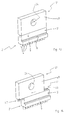
- the bar 1 shows a modified bar 1, that using modified adapters 12b standard modules 2 carries.
- the bar 1 has in its contact surface 29 trained positioning grooves 31 which extend transversely extend to the longitudinal direction of the bar 1 and at its Bottom each the fastening opening provided with an internal thread 30 is arranged.
- the positioning grooves 31 are limited parallel flanks.
- the corresponding adapter 12b can be seen from Figures 7 to 9. It points on the module side the same shape as the adapter according to FIGS. 4 to 6 or according to Figures 10 to 12. In this respect, on the corresponding parts of the above description referred.
- the adapter 12b is different formed as the adapter 12 and 12a.
- the Shape corresponds to the shape of the positioning groove 31 of the bar 1.
- the distance between his Flanks 34, 35 are dimensioned as large as the wall distance the positioning groove 31, so that the adapter 12b with little Sitting or not at Barre 1.
- the height the positioning web 33 may be slightly less than that Depth of the positioning groove 31 to ensure that the force-transmitting system between the base body 3 and the bar 1 on the surface areas 6a, 6b of the contact surface 6 and possibly still on the corresponding bar side Flat surface of section 21 of the adapter 12b limited is.
- FIG. 3 shows a modified adapter 12c and on module 2 in addition, a modified base 3a is provided.
- the embodiment is based on that of Figure 2, wherein the adapter 12c has no projections 22, 23 for securing it in the insert pocket or socket 11. Instead is the section or plate-shaped part 21 with openings 38, 39 provided, like the projections 22, 23, with respect one perpendicular through the middle of the plate-shaped Part 21 going axis not arranged symmetrically are. This gives them a clear position to deploy of the adapter in the version 11.
- the openings in the base 3a 38, 39 associated openings 41, 42 with approximately the same Diameter assigned so that the opening 41 with the opening 38 is aligned and the opening 42 with the opening 39 escapes.
- the openings 41, 42 are as positioning elements assigned serving pins 43, 44, which serve to to pin the adapter 12c to the respective module 2.
- Barre-module-adapter combinations are also conceivable (not shown), where the bar is flush with the openings 41, 42 of the module and the openings 38, 39 the adapter has additional openings, preferably blind holes, having. Using pins 43, 44, the larger one Can have length, then the adapter with the module and the Barre to be pinned.
- FIGS. 13 and 14 show a modified standard module 2 'illustrates the base body 3' with respect the vertical directions given by the shafts 4 is significantly shortened.
- the contact surface is corresponding 6 reduced to a narrow strip.
- the power transmission surface 8 is unchanged.
- the Base body 3 ' designed in the manner of a linear guide Socket 11 'to which an adapter 12' can be coupled is. This is approximately cuboid and has on its long, the base body 3 'facing A narrow strip 47 with a T-shaped cross-section on the narrow side.
- a T-slot 48 is provided as a socket along the narrow side facing the adapter 12 ' extends through the base body 3 '.
- the cross sections of the The ledge or rib 47 and the T-groove 48 match each other match, so that the adapter 12 'from the base body 3' can be removed, as can be seen from Figures 13 and 14.
- the adapter 12 ' is facing the bar 1 Side completely flat and thus has a flat contact surface 49, which only breaks through the opening 24 is.
- the contact surface 49 is flush with the contact surface 6.
- the adapter 12 'thus forms a standard adapter for Bars with non-profiled contact surfaces.
- Figures 15 and 16 illustrate module 2 ' in connection with a further modified adapter 12'a, the one except one of its projecting surface 49 Positioning web 33a completely with the adapter 12 ' Figures 13 and 14 match.
- the rib 33a corresponds to Essentially following the positioning web 33 of the adapter 12b Figure 2, 7, 8 or 9 and is intended to module 2 ' to secure on the bar 1 according to Figure 2.
- FIGS. 17 and 18 a module 2 ' illustrated with a further modified adapter 12'b.
- this adapter 12'b differs from the aforementioned by two cone-like trained on its flat surface 49 Projections 25 ', 26' which are about the pin or Projections 25, 26 of the adapter 12 according to Figure 6 correspond.
- the adapter 12'b is for connection to a bar 1 provided according to Figure 1, which has directional openings 27, 28.
- the adapter 12 ' (according to all figures 13 to 18) in two different positions attach to the base body 3 '.
- the contact surface 49 of the bar 1 faces while it in a second position just on the opposite Side lies and points away from the bar 1.
- the adapter 12 ' can therefore, if necessary, on both flat sides with different Profilings can be provided in order as an adapter to serve for two different bar systems.
- FIG. 19 shows a further embodiment of a Barre 1 with modules 2 and adapters 12 illustrated.
- the Adapter 12 is on its one of the system surfaces 29 of the bar 1 facing side flat.
- openings in the adapter 50 formed with openings 51 of the bar align and serve as directional openings.
- the diameter of the openings 50, 51 largely coincide with each other.
- the openings 51 are, for example, on both sides of the fastening opening 30 arranged. They are accordingly Openings 50 in the adapter 12 on either side of the opening 24 each between the projection 22 and 23 and the Opening 24 arranged.
- the Adapter 12 On the side facing away from the bar 1 is the Adapter 12, as in the embodiment of Figure 1, provided with the projections 22, 23. Module 2 and in particular the base body 3 also agrees with the embodiment according to Figure 1.
- the adapter 12 is on the bar 1 fixed by the pin connection.
- the basic body 3 of module 2 can thus be placed in the correct position and attached to the bar 1 by means of a fastening screw become. He grips the adapter 12 and is supported directly on the contact surface 29 of the bar 1.
- a module 2 to be attached to a bar 1, in particular a tufting module, has an adapter 12, one coupling side for a module body and has a bar specific page to accommodate to allow different bar systems.
Landscapes
- Engineering & Computer Science (AREA)
- Chemical & Material Sciences (AREA)
- Materials Engineering (AREA)
- Textile Engineering (AREA)
- Mutual Connection Of Rods And Tubes (AREA)
- Knitting Machines (AREA)
- Coupling Device And Connection With Printed Circuit (AREA)
- Clamps And Clips (AREA)
- Moulds For Moulding Plastics Or The Like (AREA)
Applications Claiming Priority (2)
| Application Number | Priority Date | Filing Date | Title |
|---|---|---|---|
| DE19928885A DE19928885C1 (de) | 1999-06-24 | 1999-06-24 | Modul mit Adapter für unterschiedliche Barren |
| DE19928885 | 1999-06-24 |
Publications (3)
| Publication Number | Publication Date |
|---|---|
| EP1063336A2 true EP1063336A2 (fr) | 2000-12-27 |
| EP1063336A3 EP1063336A3 (fr) | 2001-10-24 |
| EP1063336B1 EP1063336B1 (fr) | 2005-11-09 |
Family
ID=7912338
Family Applications (1)
| Application Number | Title | Priority Date | Filing Date |
|---|---|---|---|
| EP00106096A Expired - Lifetime EP1063336B1 (fr) | 1999-06-24 | 2000-03-30 | Module avec adaptateur pour différentes barres |
Country Status (4)
| Country | Link |
|---|---|
| US (1) | US6409030B1 (fr) |
| EP (1) | EP1063336B1 (fr) |
| JP (1) | JP3494959B2 (fr) |
| DE (2) | DE19928885C1 (fr) |
Cited By (1)
| Publication number | Priority date | Publication date | Assignee | Title |
|---|---|---|---|---|
| EP3241934A1 (fr) * | 2016-05-04 | 2017-11-08 | Groz-Beckert KG | Module d'outil textile et machine textile comprenant un module d'outil textile |
Families Citing this family (19)
| Publication number | Priority date | Publication date | Assignee | Title |
|---|---|---|---|---|
| US7398739B2 (en) * | 2005-01-13 | 2008-07-15 | Card-Monroe Corp. | Replaceable hook module |
| US20080264315A1 (en) * | 2007-04-25 | 2008-10-30 | Marshal Allen Neely | Modular Gauging Element Assembly |
| US7997219B2 (en) * | 2007-08-20 | 2011-08-16 | Card-Monroe Corp. | System and method for facilitating removal of gauge parts from hook bar modules |
| US8141697B2 (en) * | 2009-04-03 | 2012-03-27 | Ackley Machine Corporation | Method and apparatus for transporting caplets |
| USD603885S1 (en) * | 2009-04-03 | 2009-11-10 | Ackley Machine Corporation | Carrier bar |
| US8220619B2 (en) * | 2009-10-20 | 2012-07-17 | Ackley Machine Corporation | Method and apparatus for transporting pellet-shaped articles |
| USD656972S1 (en) | 2009-10-20 | 2012-04-03 | Ackley Machine Corporation | Carrier bar |
| US8382060B2 (en) | 2010-09-14 | 2013-02-26 | Bendix Commercial Vehicle Systems Llc | Component orientation element |
| USD713866S1 (en) | 2012-04-18 | 2014-09-23 | Ackley Machine Corporation | Carrier bar |
| DE202012104948U1 (de) | 2012-12-18 | 2013-01-24 | Groz-Beckert Kg | Werkzeugmodul für Textilmaschine |
| DE102012112553B3 (de) | 2012-12-18 | 2014-02-13 | Groz-Beckert Kg | Werkzeugmodul für Textilmaschine |
| US20140261121A1 (en) * | 2013-03-15 | 2014-09-18 | Card-Monroe Corp. | Needle assembly for tufting machines |
| EP3067451A1 (fr) * | 2015-03-10 | 2016-09-14 | Groz-Beckert KG | Procédé et dispositif de fabrication d'un peigne pour une machine a tisser et peigne |
| US20170218544A1 (en) * | 2016-02-03 | 2017-08-03 | Shing Ray Sewing Machine Co., Ltd. | Sewing machine needle clamp |
| TWI617401B (zh) * | 2017-01-13 | 2018-03-11 | Tool holder | |
| DE102017116043A1 (de) | 2017-07-17 | 2019-01-17 | Groz-Beckert Kg | Werkzeugmodul für Textilmaschinen |
| KR102187063B1 (ko) * | 2020-07-13 | 2020-12-04 | 김인헌 | 서브 로터가 구비되는 드론 |
| USD1056680S1 (en) | 2021-02-16 | 2025-01-07 | Card-Monroe Corp. | Gauge module |
| US11585029B2 (en) | 2021-02-16 | 2023-02-21 | Card-Monroe Corp. | Tufting maching and method of tufting |
Family Cites Families (8)
| Publication number | Priority date | Publication date | Assignee | Title |
|---|---|---|---|---|
| US4509439A (en) | 1983-09-30 | 1985-04-09 | Tuftco Corporation | Clamp insert for tufting elements in narrow gauge tufting machine |
| US4574716A (en) | 1984-12-04 | 1986-03-11 | Fieldcrest Mills, Inc. | Tufting machine with modular constructed needle bars |
| US4637329A (en) * | 1984-12-04 | 1987-01-20 | Fieldcrest Mills, Inc. | Tufting machine with modular constructed needle bars |
| DE8814944U1 (de) | 1988-12-01 | 1990-04-05 | Jos. Zimmermann GmbH & Co KG, 5100 Aachen | Modul mit Tuftingwerkzeugen |
| US5295450A (en) | 1992-05-01 | 1994-03-22 | Card-Monroe Corp. | Tufting machine with self-aligning gauging modules |
| DE4406412C1 (de) * | 1994-02-28 | 1995-04-27 | Zimmermann Jos Gmbh & Co Kg | Barrenanordnung |
| DE29520281U1 (de) * | 1995-12-21 | 1996-03-14 | Jos. Zimmermann GmbH & Co KG, 52064 Aachen | Modul und Barre für Tuftingwerkzeuge |
| GB9924840D0 (en) * | 1999-10-20 | 1999-12-22 | Cobble Blackburn Ltd | Cut pile tufting machine cutting elements |
-
1999
- 1999-06-24 DE DE19928885A patent/DE19928885C1/de not_active Expired - Fee Related
-
2000
- 2000-03-30 EP EP00106096A patent/EP1063336B1/fr not_active Expired - Lifetime
- 2000-03-30 DE DE50011542T patent/DE50011542D1/de not_active Expired - Lifetime
- 2000-06-21 JP JP2000186483A patent/JP3494959B2/ja not_active Expired - Fee Related
- 2000-06-26 US US09/603,766 patent/US6409030B1/en not_active Expired - Lifetime
Cited By (4)
| Publication number | Priority date | Publication date | Assignee | Title |
|---|---|---|---|---|
| EP3241934A1 (fr) * | 2016-05-04 | 2017-11-08 | Groz-Beckert KG | Module d'outil textile et machine textile comprenant un module d'outil textile |
| WO2017191002A1 (fr) * | 2016-05-04 | 2017-11-09 | Groz-Beckert Kg | Module d'outil textile et machine textile comprenant un module d'outil textile |
| CN109072509A (zh) * | 2016-05-04 | 2018-12-21 | 格罗兹-贝克特公司 | 纺织工具模块和具有纺织工具模块的纺织机 |
| CN109072509B (zh) * | 2016-05-04 | 2021-05-18 | 格罗兹-贝克特公司 | 纺织工具模块和具有纺织工具模块的纺织机 |
Also Published As
| Publication number | Publication date |
|---|---|
| US6409030B1 (en) | 2002-06-25 |
| DE19928885C1 (de) | 2001-03-29 |
| EP1063336A3 (fr) | 2001-10-24 |
| DE50011542D1 (de) | 2005-12-15 |
| JP2001032166A (ja) | 2001-02-06 |
| EP1063336B1 (fr) | 2005-11-09 |
| JP3494959B2 (ja) | 2004-02-09 |
Similar Documents
| Publication | Publication Date | Title |
|---|---|---|
| EP1063336A2 (fr) | Module avec adaptateur pour différentes barres | |
| DE60002994T2 (de) | Werkzeughalter mit ersetzbarem einsatzträger | |
| DE4223642C2 (de) | Tufting-Maschine mit mindestens einer Barre und mehreren an die Barre nebeneinander ansetzbaren Moduln | |
| DE3886409T2 (de) | Werkzeughalter auf lochplatten. | |
| EP1071542A1 (fr) | Systeme et procede de serrage pour la fixation de pieces a usiner | |
| EP0824613A1 (fr) | Barre munie de modules pour outils de tufting | |
| DE29816671U1 (de) | Werkzeughalter mit verschiebbaren Verbindern | |
| DE4428310A1 (de) | Befestigungsvorrichtung für ein Werkzeug oder Werkstück | |
| DE10349381B4 (de) | Webschaft mit neuartigem Eckverbinder | |
| EP0958422B1 (fr) | Module et barre pour outils de tufting | |
| EP0539687B1 (fr) | Joint perpendiculaire pour des profilés avec des rainures longitudinales | |
| EP1988198B1 (fr) | Ensemble d'outils et barre pour machine à tricoter de type chaîne | |
| EP2045384B1 (fr) | Aiguille pour un métier à mailles jetées | |
| EP0116260A2 (fr) | Dispositif pour fixer un objet | |
| EP3535824B1 (fr) | Support de jeu de barres et ensemble correspondant | |
| WO2017140493A1 (fr) | Ensemble support pour supporter un boîtier électronique | |
| EP1225347B1 (fr) | Elément de fixation et dispositiv de fixation pour profilés | |
| DE102018120656B3 (de) | Führungsschienensystem und mobiles Arbeitssystem | |
| DE8609264U1 (de) | Mehrzweck-Drehwerkzeug | |
| DE102018004359A1 (de) | Objekthalteeinrichtung zur Anordnung an einem Profilstab | |
| EP3819198A1 (fr) | Adaptateur pour attacher des objets au réservoir d'une moto | |
| EP1227251B1 (fr) | Profilé à contre-dépouille | |
| EP0321463B1 (fr) | Fixation pour appareils auxiliaires | |
| DE8704548U1 (de) | Querverbinder für Profilstäbe | |
| DE102017130437A1 (de) | Schnellwechsler, Adapter und Schnellwechselsystem |
Legal Events
| Date | Code | Title | Description |
|---|---|---|---|
| PUAI | Public reference made under article 153(3) epc to a published international application that has entered the european phase |
Free format text: ORIGINAL CODE: 0009012 |
|
| AK | Designated contracting states |
Kind code of ref document: A2 Designated state(s): AT BE CH CY DE DK ES FI FR GB GR IE IT LI LU MC NL PT SE Kind code of ref document: A2 Designated state(s): BE DE GB NL |
|
| AX | Request for extension of the european patent |
Free format text: AL;LT;LV;MK;RO;SI |
|
| PUAL | Search report despatched |
Free format text: ORIGINAL CODE: 0009013 |
|
| AK | Designated contracting states |
Kind code of ref document: A3 Designated state(s): AT BE CH CY DE DK ES FI FR GB GR IE IT LI LU MC NL PT SE |
|
| AX | Request for extension of the european patent |
Free format text: AL;LT;LV;MK;RO;SI |
|
| 17P | Request for examination filed |
Effective date: 20011002 |
|
| AKX | Designation fees paid |
Free format text: BE DE GB NL |
|
| 17Q | First examination report despatched |
Effective date: 20021106 |
|
| GRAP | Despatch of communication of intention to grant a patent |
Free format text: ORIGINAL CODE: EPIDOSNIGR1 |
|
| GRAS | Grant fee paid |
Free format text: ORIGINAL CODE: EPIDOSNIGR3 |
|
| GRAP | Despatch of communication of intention to grant a patent |
Free format text: ORIGINAL CODE: EPIDOSNIGR1 |
|
| GRAA | (expected) grant |
Free format text: ORIGINAL CODE: 0009210 |
|
| AK | Designated contracting states |
Kind code of ref document: B1 Designated state(s): BE DE GB NL |
|
| REG | Reference to a national code |
Ref country code: GB Ref legal event code: FG4D Free format text: NOT ENGLISH |
|
| GBT | Gb: translation of ep patent filed (gb section 77(6)(a)/1977) |
Effective date: 20051109 |
|
| REF | Corresponds to: |
Ref document number: 50011542 Country of ref document: DE Date of ref document: 20051215 Kind code of ref document: P |
|
| PLBE | No opposition filed within time limit |
Free format text: ORIGINAL CODE: 0009261 |
|
| STAA | Information on the status of an ep patent application or granted ep patent |
Free format text: STATUS: NO OPPOSITION FILED WITHIN TIME LIMIT |
|
| 26N | No opposition filed |
Effective date: 20060810 |
|
| PGFP | Annual fee paid to national office [announced via postgrant information from national office to epo] |
Ref country code: NL Payment date: 20170320 Year of fee payment: 18 |
|
| PGFP | Annual fee paid to national office [announced via postgrant information from national office to epo] |
Ref country code: GB Payment date: 20170329 Year of fee payment: 18 Ref country code: BE Payment date: 20170124 Year of fee payment: 18 |
|
| PGFP | Annual fee paid to national office [announced via postgrant information from national office to epo] |
Ref country code: DE Payment date: 20170331 Year of fee payment: 18 |
|
| REG | Reference to a national code |
Ref country code: DE Ref legal event code: R119 Ref document number: 50011542 Country of ref document: DE |
|
| REG | Reference to a national code |
Ref country code: NL Ref legal event code: MM Effective date: 20180401 |
|
| GBPC | Gb: european patent ceased through non-payment of renewal fee |
Effective date: 20180330 |
|
| REG | Reference to a national code |
Ref country code: BE Ref legal event code: MM Effective date: 20180331 |
|
| PG25 | Lapsed in a contracting state [announced via postgrant information from national office to epo] |
Ref country code: NL Free format text: LAPSE BECAUSE OF NON-PAYMENT OF DUE FEES Effective date: 20180401 |
|
| PG25 | Lapsed in a contracting state [announced via postgrant information from national office to epo] |
Ref country code: DE Free format text: LAPSE BECAUSE OF NON-PAYMENT OF DUE FEES Effective date: 20181002 |
|
| PG25 | Lapsed in a contracting state [announced via postgrant information from national office to epo] |
Ref country code: BE Free format text: LAPSE BECAUSE OF NON-PAYMENT OF DUE FEES Effective date: 20180331 Ref country code: GB Free format text: LAPSE BECAUSE OF NON-PAYMENT OF DUE FEES Effective date: 20180330 |