EP1063374A1 - Schlüssel, insbesondere für Kraftfahrzeuge, mit einem Schlüsselbart und einem Griffteil - Google Patents
Schlüssel, insbesondere für Kraftfahrzeuge, mit einem Schlüsselbart und einem Griffteil Download PDFInfo
- Publication number
- EP1063374A1 EP1063374A1 EP00401759A EP00401759A EP1063374A1 EP 1063374 A1 EP1063374 A1 EP 1063374A1 EP 00401759 A EP00401759 A EP 00401759A EP 00401759 A EP00401759 A EP 00401759A EP 1063374 A1 EP1063374 A1 EP 1063374A1
- Authority
- EP
- European Patent Office
- Prior art keywords
- head
- bit
- pivot
- housing
- support
- Prior art date
- Legal status (The legal status is an assumption and is not a legal conclusion. Google has not performed a legal analysis and makes no representation as to the accuracy of the status listed.)
- Granted
Links
Images



Classifications
-
- E—FIXED CONSTRUCTIONS
- E05—LOCKS; KEYS; WINDOW OR DOOR FITTINGS; SAFES
- E05B—LOCKS; ACCESSORIES THEREFOR; HANDCUFFS
- E05B19/00—Keys; Accessories therefor
- E05B19/04—Construction of the bow or head of the key; Attaching the bow to the shank
- E05B19/043—Construction of the bow or head of the key; Attaching the bow to the shank the shank being pivotably mounted on the bow, e.g. for storage
-
- A—HUMAN NECESSITIES
- A45—HAND OR TRAVELLING ARTICLES
- A45C—PURSES; LUGGAGE; HAND CARRIED BAGS
- A45C11/00—Receptacles for purposes not provided for in groups A45C1/00-A45C9/00
- A45C11/32—Bags or wallets for holding keys
- A45C11/324—Bags or wallets for holding keys with pivoting keys
-
- G—PHYSICS
- G07—CHECKING-DEVICES
- G07C—TIME OR ATTENDANCE REGISTERS; REGISTERING OR INDICATING THE WORKING OF MACHINES; GENERATING RANDOM NUMBERS; VOTING OR LOTTERY APPARATUS; ARRANGEMENTS, SYSTEMS OR APPARATUS FOR CHECKING NOT PROVIDED FOR ELSEWHERE
- G07C9/00—Individual registration on entry or exit
- G07C9/00174—Electronically operated locks; Circuits therefor; Nonmechanical keys therefor, e.g. passive or active electrical keys or other data carriers without mechanical keys
- G07C9/00944—Details of construction or manufacture
-
- G—PHYSICS
- G07—CHECKING-DEVICES
- G07C—TIME OR ATTENDANCE REGISTERS; REGISTERING OR INDICATING THE WORKING OF MACHINES; GENERATING RANDOM NUMBERS; VOTING OR LOTTERY APPARATUS; ARRANGEMENTS, SYSTEMS OR APPARATUS FOR CHECKING NOT PROVIDED FOR ELSEWHERE
- G07C9/00—Individual registration on entry or exit
- G07C9/00174—Electronically operated locks; Circuits therefor; Nonmechanical keys therefor, e.g. passive or active electrical keys or other data carriers without mechanical keys
- G07C9/00944—Details of construction or manufacture
- G07C2009/00952—Electronic keys comprising a mechanical key within their housing, e.g. extractable or retractable emergency key
Definitions
- the present invention relates to keys, in particular for a vehicle automobile, comprising a bit-forming part and a part of grip on which the bit portion is pivotally mounted between a position of use where it extends axially said part of gripping and a stowed position where it is retracted therein.
- the gripping boxes for retractable bit keys are generally constituted by two half-shells which are closed one on the other.
- the mechanism which resembles the bit elastically in its position extended by the actuation of a push button by a operator and which ensures the locking of said bit in its position retracted, is directly accessible to the operator if he opens the two half-shells of its gripping case.
- An object of the invention is to propose an insert key structure retractable which does not have this drawback.
- Another object of the invention is to overcome this other drawback.
- the invention provides a key comprising a housing, a bit which includes an insert and a head portion which is mounted pivotable about an axis of said housing so that the bit can pivot between a position where it is retracted into the housing and a position of use where it came out with respect to said housing, as well as means forming a spring which ensures the elastic return of the bit in its extended position, under the effect of the actuation of a push button, characterized in that it includes a support piece including less part is juxtaposed at the head of the bit, means spring which ensure the elastic return of the bit forming part bearing at one end on said support piece and at their other end on the head bit, said head and said support part being inserted in a housing at the front of the housing, so that the support part is blocked in said housing, while the bit can pivot between its position retracted and its position extended.
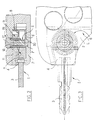
- the mechanical key which is illustrated in the figures has a part 1 forming a bit and a case 2.
- Part 1 forming a bit comprises a flat metal insert 3 and a part 4 which constitutes the head of the insert and which is made of a material plastic and is overmolded on an end portion of said insert.
- the housing 2 has a generally flat parallelepiped shape rounded.
- blind housing L which extends in its edge and which is opening on one side of said housing 2 at the front and on a portion in the length of it.
- the qualifiers front / rear must be understood in relation to the direction of introduction of the metal insert 3 in the cylinder of a lock, the metal insert 3 being at the front of the key when it comes out of the case 2, the case 2 then being at the rear.
- Housing L receives a pivoting mechanism block at the front of which the head 4 is a part, its rear part which opens onto the edge side of the housing 2 being for its part intended to receive the metal insert flat 3 when the latter is in its retracted position.
- the front part of the housing 2, in which is formed the housing L is molded in one piece.
- the rear part of this piece can be conformed to the shell and receive control electronics to RF or IR type distance.
- This half-shell is then closed by a another half-shell or a hatch which relates to this rear part.
- the head 4 of the part 1 forming a bit is a hollow head in which extends a helical spring 5 whose axis is perpendicular to the plane of the insert 3. This spring 5 bears on the bottom 6 of said head hollow 4.
- This hollow head 4 also has inside a bearing plate 7, parallel to the plane of the insert 3, on which a flat spring is received in spiral 8.
- This flat spring 8 ends in two end branches which extend perpendicularly to said spring, one of these branches (the one at its smallest diameter) engaging in a holding hole (not shown in the figures) that the bearing 7 has to receive it, the other (the one at its largest diameter) engaging in a holding slot 10 which is provided in a part 9 forming support.
- This part 9 has a main wall 11 and an edge 12 which extends from said wall 11, perpendicular thereto.
- the wall 11 is intended to be attached to said hollow part 4 to close it. It has a central allowance 11a whose edges are generally circular in shape. The diameter of this allowance is slightly smaller than the inside diameter of the hollow head 4, so that this additional thickness 11a contributes to guiding the head 4 in its pivoting around its axis.
- the edge 12 is also shaped so as to guide externally the head 4 in its pivoting around its axis.
- the bottom of the part 4 has a pivot pin P which extends projecting from said bottom, outside of part 4 and which is centered on the pivot axis of said part 4.
- This pawn P defines with a part 13 which will now be described a pivot axis for the whole of part 1 forming a bit.
- This part 13 is a generally cylindrical part with the interior of which extends the coil spring 5, the diameter of which outside is slightly smaller than the inside diameter of said part 13.
- This part 13 is intended to be received partially in the head 4 and to cross the wall 11.
- the diameter of the orifice 14 that the wall 11 has for this purpose is slightly greater than the diameter of the through part of said part 13.
- This part 13 also has two legs 15 which extend in protruding outside said piece 13, on the side of said piece 4, on substantially half the height of the piece 13.
- the axes along which these legs 15 extend are separated by 145 ° relative to each other.
- the wall 11 has meanwhile, on the edge of the orifice 14, notches 16 which are intended to receive the legs 15 on the one hand in the output position of the piece 1 forming a bit and on the other hand in its retracted position, to block the part 13 forming a pivot and the assembly of the part 1 which is integral with it in rotation, in one or the other of these two positions.
- the part forming a pivot 13 and the hollow sheet 4 of the bit are integral in rotation via the legs 15, the part forming pivot 13 and the support part 9 being in turn movable in rotation one compared to each other.
- the tabs and the notches 16 cooperate to block the pivot piece and the bit when the latter is in its position out or in its retracted position.
- the pivoting mechanism also includes a cap 17 which has a foot 18 intended to come to bear on the helical spring 5, inside the part 13 forming a pivot.
- said part 13 forming a pivot has an inner annular bulge which cooperates with a groove annular that said foot 18 has to achieve a snap resiliently locking the cap 17 on the part 13.
- the pivoting mechanism which has just been described is intended to be received in the front part of the housing L, which front part has a shape complementary to the block that constitutes the head 4 and the part 9 attached to it.
- the wall of the housing 2 against which is directly juxtaposed the wall 11 is crossed by an orifice 19 which receives the head of the cap 17 and possibly the upper part of the part 13 forming a pivot.
- the wall of the housing 2 which is opposite this orifice 19 has as to it a housing 20 in which is received the pin P forming a pivot and which is of complementary form to this one.
- the two springs 5 and 8 are initially placed in the head hollow 4, the inner end of the spiral spring 8 being engaged in the holding orifice provided for receiving it in said head 4.
- the support piece 9 is attached to said head 4 and said piece 13 forming a pivot. Said part 9 is positioned so that part 1 forming a bit is in abutment with respect to the edge 12, in the position which must be its own with respect to said edge 12 in its position not retracted.
- the block thus constituted is forcibly engaged in the housing L of the case 2, keeping the coil spring 5 compressed.
- this cap 17 can be personalized from a housing to another.
- the pivoting key is then in its non-retracted position and ready to use.
- the operator presses the button that constitutes the head of the cap for disengaging the lugs 15 from the part 13 forming a pivot by compared to the complementary notches 16 in which these legs 15 were engaged in the non-retracted position of part 1 forming bit.
- the part 1 forming a bit Due to the torsional torque exerted by the flat spiral spring 8, the part 1 forming a bit is elastically recalled to its position where the insert is completely out of the housing and is in abutment on the edge 12.
- the wall 11 of the room 9 forming a support could be split, the part 9 then having a U-shaped cross section whose bottom would be constituted by the edge 12.
- the pivot pin P projecting from the bottom 6 of the head 4 is received in the orifice 14 of one of the two walls 11.
- the spring means could not include only one helical spring which, instead of springs 5 and 8, would be used for times to recall bit 1 to its extended position and to push the button pusher 17.
Landscapes
- Engineering & Computer Science (AREA)
- Manufacturing & Machinery (AREA)
- Physics & Mathematics (AREA)
- General Physics & Mathematics (AREA)
- Lock And Its Accessories (AREA)
- Pivots And Pivotal Connections (AREA)
Applications Claiming Priority (2)
| Application Number | Priority Date | Filing Date | Title |
|---|---|---|---|
| FR9907934 | 1999-06-22 | ||
| FR9907934A FR2795443B1 (fr) | 1999-06-22 | 1999-06-22 | Cles, notamment de vehicule automobile, comportant une partie formant panneton et une partie de prehension |
Publications (2)
| Publication Number | Publication Date |
|---|---|
| EP1063374A1 true EP1063374A1 (de) | 2000-12-27 |
| EP1063374B1 EP1063374B1 (de) | 2004-12-08 |
Family
ID=9547142
Family Applications (1)
| Application Number | Title | Priority Date | Filing Date |
|---|---|---|---|
| EP20000401759 Expired - Lifetime EP1063374B1 (de) | 1999-06-22 | 2000-06-20 | Schlüssel, insbesondere für Kraftfahrzeuge, mit einem Schlüsselbart und einem Griffteil |
Country Status (4)
| Country | Link |
|---|---|
| EP (1) | EP1063374B1 (de) |
| DE (1) | DE60016508T2 (de) |
| ES (1) | ES2232394T3 (de) |
| FR (1) | FR2795443B1 (de) |
Cited By (5)
| Publication number | Priority date | Publication date | Assignee | Title |
|---|---|---|---|---|
| NL1022733C2 (nl) * | 2003-02-19 | 2004-08-23 | Stenman Holland Nv | Fietsslot voorzien van klapsleutel. |
| EP1609931A1 (de) * | 2004-06-23 | 2005-12-28 | Delphi Technologies, Inc. | Fernsteuervorrichtung mit einklappbarem Schlüssel, insbesondere für Kraftfahrzeug |
| WO2009049839A1 (fr) * | 2007-10-19 | 2009-04-23 | Johnson Controls Technology Company | Cle pivotante a blocage en position renforce, pour l'actionnement d'une serrure |
| ITTO20080536A1 (it) * | 2008-07-11 | 2010-01-12 | Alcibiade Cardanobile | Portachiavi con chiavi ad estrazione automatica |
| WO2011061279A1 (fr) * | 2009-11-20 | 2011-05-26 | Valeo Securite Habitacle | Cle a insert escamotable a resistance mecanique amelioree |
Families Citing this family (1)
| Publication number | Priority date | Publication date | Assignee | Title |
|---|---|---|---|---|
| FR2915759B1 (fr) | 2007-05-03 | 2009-07-03 | Johnson Controls Tech Co | Cle de serrure retractable a pivot renforce |
Citations (4)
| Publication number | Priority date | Publication date | Assignee | Title |
|---|---|---|---|---|
| US3765201A (en) * | 1972-10-16 | 1973-10-16 | D Humphrey | Key holder |
| FR2558696A1 (fr) * | 1984-01-31 | 1985-08-02 | Insignes Artistiques Fab | Porte-cles |
| EP0267429A1 (de) * | 1986-10-20 | 1988-05-18 | Siemens Aktiengesellschaft | Gerät zum Fernsteuern einer mit einem Empfänger ausgerüsteten Schliessanlage, insbesondere für Kraftfahrzeuge |
| DE3902537A1 (de) * | 1989-01-28 | 1990-08-09 | Daimler Benz Ag | Schluesselbehaelter mit ausschwenkbarem flachschluessel |
Family Cites Families (2)
| Publication number | Priority date | Publication date | Assignee | Title |
|---|---|---|---|---|
| DE3842790C1 (de) | 1988-12-20 | 1990-04-05 | Daimler-Benz Aktiengesellschaft, 7000 Stuttgart, De | |
| DE4226579C2 (de) | 1992-08-11 | 1995-02-16 | Daimler Benz Ag | Kompaktsender zur Fernansteuerung einer einen Schließzylinder umfassenden Schließeinrichtung |
-
1999
- 1999-06-22 FR FR9907934A patent/FR2795443B1/fr not_active Expired - Lifetime
-
2000
- 2000-06-20 EP EP20000401759 patent/EP1063374B1/de not_active Expired - Lifetime
- 2000-06-20 DE DE2000616508 patent/DE60016508T2/de not_active Expired - Lifetime
- 2000-06-20 ES ES00401759T patent/ES2232394T3/es not_active Expired - Lifetime
Patent Citations (4)
| Publication number | Priority date | Publication date | Assignee | Title |
|---|---|---|---|---|
| US3765201A (en) * | 1972-10-16 | 1973-10-16 | D Humphrey | Key holder |
| FR2558696A1 (fr) * | 1984-01-31 | 1985-08-02 | Insignes Artistiques Fab | Porte-cles |
| EP0267429A1 (de) * | 1986-10-20 | 1988-05-18 | Siemens Aktiengesellschaft | Gerät zum Fernsteuern einer mit einem Empfänger ausgerüsteten Schliessanlage, insbesondere für Kraftfahrzeuge |
| DE3902537A1 (de) * | 1989-01-28 | 1990-08-09 | Daimler Benz Ag | Schluesselbehaelter mit ausschwenkbarem flachschluessel |
Cited By (10)
| Publication number | Priority date | Publication date | Assignee | Title |
|---|---|---|---|---|
| NL1022733C2 (nl) * | 2003-02-19 | 2004-08-23 | Stenman Holland Nv | Fietsslot voorzien van klapsleutel. |
| EP1609931A1 (de) * | 2004-06-23 | 2005-12-28 | Delphi Technologies, Inc. | Fernsteuervorrichtung mit einklappbarem Schlüssel, insbesondere für Kraftfahrzeug |
| WO2009049839A1 (fr) * | 2007-10-19 | 2009-04-23 | Johnson Controls Technology Company | Cle pivotante a blocage en position renforce, pour l'actionnement d'une serrure |
| CN101827989B (zh) * | 2007-10-19 | 2013-04-03 | 约翰逊控制技术公司 | 用于开锁的带有加强的位置锁定的可枢转钥匙 |
| ITTO20080536A1 (it) * | 2008-07-11 | 2010-01-12 | Alcibiade Cardanobile | Portachiavi con chiavi ad estrazione automatica |
| WO2010004399A1 (en) * | 2008-07-11 | 2010-01-14 | Alcibiade Cardanobile | Key-holder with automatic key extraction |
| WO2011061279A1 (fr) * | 2009-11-20 | 2011-05-26 | Valeo Securite Habitacle | Cle a insert escamotable a resistance mecanique amelioree |
| FR2952956A1 (fr) * | 2009-11-20 | 2011-05-27 | Valeo Securite Habitacle | Cle a insert escamotable a resistance mecanique amelioree |
| JP2013511634A (ja) * | 2009-11-20 | 2013-04-04 | ヴァレオ セキュリテ アビタクル | 機械的強度を向上したインサート収納可能キー |
| US8479546B2 (en) | 2009-11-20 | 2013-07-09 | Valeo Securite Habitacle | Key having a retractable insert with improved mechanical strength |
Also Published As
| Publication number | Publication date |
|---|---|
| DE60016508T2 (de) | 2005-12-15 |
| FR2795443A1 (fr) | 2000-12-29 |
| EP1063374B1 (de) | 2004-12-08 |
| FR2795443B1 (fr) | 2001-09-14 |
| DE60016508D1 (de) | 2005-01-13 |
| ES2232394T3 (es) | 2005-06-01 |
Similar Documents
| Publication | Publication Date | Title |
|---|---|---|
| EP1578675B1 (de) | Flaschenverschluss mit kontrollierter öffnungsbewegung | |
| EP2331777B1 (de) | Schlüssel mit klappeinsatz | |
| EP2183987B1 (de) | Zigarrenschneider | |
| EP0985788B1 (de) | Schlüssel, insbesondere für Kraftfahrzeuge, mit Schlüsselkopf bestehend aus einem Fernbedienungsgehäuse mit herausklappbarem Einsatz und Verfahren zu seiner Herstellung | |
| FR2948402A1 (fr) | Commande d'ouverture exterieure d'un ouvrant de vehicule automobile et ouvrant equipe d'une telle commande d'ouverture | |
| EP2795025B1 (de) | Schlüssel mit einziehbarem einsatz und entsprechendes auslösungsmodul | |
| EP2114734B1 (de) | Diebstahlsicherung für ein fahrzeug mit ausgestattetem gehäuse und verfahren zur herstellung dieses gehäuses | |
| FR2912543A1 (fr) | Commutateur a verrouillage | |
| EP2201200A1 (de) | Drehbarer schlüssel mit verstärkter rastung zur betätigung eines schlosses | |
| EP4176756B1 (de) | Einsatzteil für uhrenarmband | |
| EP1063374B1 (de) | Schlüssel, insbesondere für Kraftfahrzeuge, mit einem Schlüsselbart und einem Griffteil | |
| EP0404688A1 (de) | Abnehmbarer Wasserbehälter für ein Haushaltsgerät und Haushaltsgerät mit einem solchen Behälter | |
| EP1179449B1 (de) | Mittelkonsole, insbesondere für den Kraftfahrzeuginnenraum | |
| EP0688692A1 (de) | Schwenkbarer Tankverschlussdeckel für Personenkraftwagen | |
| FR2864884A1 (fr) | Boitier a ouverture automatique | |
| FR2753475A1 (fr) | Verrou de poignee de portiere de vehicule automobile comportant un capuchon coulissant de protection du verrou | |
| EP2682546B1 (de) | Ablageeinheit für Fahrzeug, und Armaturenbrett mit einer solchen Einheit | |
| EP2804782B1 (de) | Herausnehmbare konsole für den innenraum eines kraftfahrzeugs | |
| EP1895078B1 (de) | Einklappbare Schlüsselvorrichtung und Montageverfahren | |
| EP1609931B1 (de) | Fernsteuervorrichtung mit einklappbarem Schlüssel, insbesondere für Kraftfahrzeug | |
| FR2809090A3 (fr) | Boite a couvercle pivotant | |
| WO2021122040A1 (fr) | Mecanisme pour un commutateur electrique,ensemble electrique et commutateur electrique associes | |
| FR2877818A1 (fr) | Boite, notamment destinee a contenir un ou plusieurs produits cosmetiques | |
| EP4185490A1 (de) | Lager mit mobilem innenverschluss | |
| EP0880155B1 (de) | Elektrischer Schlie mechanismus, der durch einen blockierbaren Schalter geschaltet wird. |
Legal Events
| Date | Code | Title | Description |
|---|---|---|---|
| PUAI | Public reference made under article 153(3) epc to a published international application that has entered the european phase |
Free format text: ORIGINAL CODE: 0009012 |
|
| AK | Designated contracting states |
Kind code of ref document: A1 Designated state(s): DE ES GB IT |
|
| AX | Request for extension of the european patent |
Free format text: AL;LT;LV;MK;RO;SI |
|
| 17P | Request for examination filed |
Effective date: 20010627 |
|
| AKX | Designation fees paid |
Free format text: DE ES GB IT |
|
| RAP1 | Party data changed (applicant data changed or rights of an application transferred) |
Owner name: VALEO SECURITE HABITACLE |
|
| RAP1 | Party data changed (applicant data changed or rights of an application transferred) |
Owner name: VALEO SECURITE HABITACLE S.A.S. |
|
| GRAP | Despatch of communication of intention to grant a patent |
Free format text: ORIGINAL CODE: EPIDOSNIGR1 |
|
| GRAS | Grant fee paid |
Free format text: ORIGINAL CODE: EPIDOSNIGR3 |
|
| GRAA | (expected) grant |
Free format text: ORIGINAL CODE: 0009210 |
|
| AK | Designated contracting states |
Kind code of ref document: B1 Designated state(s): DE ES GB IT |
|
| REG | Reference to a national code |
Ref country code: GB Ref legal event code: FG4D Free format text: NOT ENGLISH |
|
| REF | Corresponds to: |
Ref document number: 60016508 Country of ref document: DE Date of ref document: 20050113 Kind code of ref document: P |
|
| GBT | Gb: translation of ep patent filed (gb section 77(6)(a)/1977) |
Effective date: 20050301 |
|
| REG | Reference to a national code |
Ref country code: ES Ref legal event code: FG2A Ref document number: 2232394 Country of ref document: ES Kind code of ref document: T3 |
|
| PLBE | No opposition filed within time limit |
Free format text: ORIGINAL CODE: 0009261 |
|
| STAA | Information on the status of an ep patent application or granted ep patent |
Free format text: STATUS: NO OPPOSITION FILED WITHIN TIME LIMIT |
|
| 26N | No opposition filed |
Effective date: 20050909 |
|
| PGFP | Annual fee paid to national office [announced via postgrant information from national office to epo] |
Ref country code: DE Payment date: 20180607 Year of fee payment: 19 |
|
| PGFP | Annual fee paid to national office [announced via postgrant information from national office to epo] |
Ref country code: IT Payment date: 20180612 Year of fee payment: 19 |
|
| PGFP | Annual fee paid to national office [announced via postgrant information from national office to epo] |
Ref country code: GB Payment date: 20180613 Year of fee payment: 19 Ref country code: ES Payment date: 20180725 Year of fee payment: 19 |
|
| REG | Reference to a national code |
Ref country code: DE Ref legal event code: R119 Ref document number: 60016508 Country of ref document: DE |
|
| GBPC | Gb: european patent ceased through non-payment of renewal fee |
Effective date: 20190620 |
|
| PG25 | Lapsed in a contracting state [announced via postgrant information from national office to epo] |
Ref country code: IT Free format text: LAPSE BECAUSE OF NON-PAYMENT OF DUE FEES Effective date: 20190620 Ref country code: DE Free format text: LAPSE BECAUSE OF NON-PAYMENT OF DUE FEES Effective date: 20200101 Ref country code: GB Free format text: LAPSE BECAUSE OF NON-PAYMENT OF DUE FEES Effective date: 20190620 |
|
| REG | Reference to a national code |
Ref country code: ES Ref legal event code: FD2A Effective date: 20201028 |
|
| PG25 | Lapsed in a contracting state [announced via postgrant information from national office to epo] |
Ref country code: ES Free format text: LAPSE BECAUSE OF NON-PAYMENT OF DUE FEES Effective date: 20190621 |