EP1063425A2 - Zündvorrichtung für Brennkraftmaschine - Google Patents
Zündvorrichtung für Brennkraftmaschine Download PDFInfo
- Publication number
- EP1063425A2 EP1063425A2 EP00110130A EP00110130A EP1063425A2 EP 1063425 A2 EP1063425 A2 EP 1063425A2 EP 00110130 A EP00110130 A EP 00110130A EP 00110130 A EP00110130 A EP 00110130A EP 1063425 A2 EP1063425 A2 EP 1063425A2
- Authority
- EP
- European Patent Office
- Prior art keywords
- case
- ignition device
- core
- center core
- coil
- Prior art date
- Legal status (The legal status is an assumption and is not a legal conclusion. Google has not performed a legal analysis and makes no representation as to the accuracy of the status listed.)
- Withdrawn
Links
Images




Classifications
-
- F—MECHANICAL ENGINEERING; LIGHTING; HEATING; WEAPONS; BLASTING
- F02—COMBUSTION ENGINES; HOT-GAS OR COMBUSTION-PRODUCT ENGINE PLANTS
- F02P—IGNITION, OTHER THAN COMPRESSION IGNITION, FOR INTERNAL-COMBUSTION ENGINES; TESTING OF IGNITION TIMING IN COMPRESSION-IGNITION ENGINES
- F02P3/00—Other installations
- F02P3/02—Other installations having inductive energy storage, e.g. arrangements of induction coils
Definitions
- the present invention relates to an ignition device for an internal combustion engine, and particularly to a cylindrical ignition device which is received within a plug hole.
- a structure is made such that the side core is formed to have a circular pipe shape by using a silicon steel strip having a thickness of 0.2 to 0.7 mm and one slit is formed therein (which shape is, hereinafter, referred to as "a C-type shape").
- the center core is manufactured by laminating a plural pieces of silicon steel strip.
- An object of the present invention is to obtain an ignition device which can improve productivity for producing the ignition device while improving an efficiency of converting a magnetic flux by modifying a material and a structure of a center core.
- Another object of the present invention is to obtain an ignition device which can reduce the number of parts and the number of the steps of the assembling process thereof while improving an efficiency of converting a magnetic flux by modifying a material and the structure of a side core and by modifying the shape of a case.
- an ignition device for an internal combustion engine in which there is used, as a material of a center core, a thin film amorphous silicon steel strip of not more than 0.1 mm in thickness or a crystallized silicon steel strip of not more than 0.23 mm in thickness, each of which amorphous and crystallized silicon steel strips has a flux density B8 ⁇ 1.4T at a direct current magnetizing force of 800 A/m when measured in accordance with the direct current magnetizing characteristic test prescribed in JIS C2550, Paragraph 7.2, and regarding the center core the shape thereof is formed to have a spirally wound, cylindrical shape. Accordingly, in the invention the space factor thereof is improved and the efficiency of converting a magnetic flux is improved. Further, the productivity of the ignition device can be improved by employing the spiral structure.
- an ignition device for an internal combustion engine in which a silicon steel strip having a thickness not more than 0.2 mm is used to reduce eddy current loss for a material of the side core and in which the shape thereof is formed to have a spirally wound, cylindrical shape.
- the space factor thereof is improved and the efficiency of converting a magnetic flux is improved.
- a productivity can be improved by employing the spirally wound, cylindrical structure and the number of the steps of an assembling process can be reduced by making the parts formed in one unit.
- Fig. 1 is a cross sectional view which shows a structure of an ignition device provided in accordance with an embodiment of the present invention.
- a primary bobbin 1 is formed with a thermoplastic synthetic resin and a primary coil 2 is wound around the primary bobbin (1). Further, a secondary coil 4 is wound around a secondary bobbin 3 formed with a thermoplastic synthetic resin.
- a coil portion case 5 is formed with the same thermoplastic synthetic resin as that of the primary bobbin 1, and is arranged around an outer side of the primary coil 2.
- a center core 6 is arranged in an inner side of the secondary bobbin 3.
- a side core 7 opposed to the center core is arranged in an outer side of the primary coil 2 and in an outer side of the coil portion case 5. Further, a magnet which generates a magnetic flux in a direction opposite to a direction of a magnetic flux generated in the primary coil 2 is provided at one end or both ends of the center core 6.
- a flexible epoxy resin 8 for reducing a stress is made to fill between the center core 6 and the secondary bobbin 3.
- These constituting elements are concentrically arranged from the inner side toward the outer side thereof in the order of the center core 6, the secondary coil 4, the primary coil 2, the case 5 and the side core 7. Then, the coil portion-constituting elements are forced into the case 5, and an insulating filler such as an insulating epoxy resin 10 for insulating a high voltage is made to fill therein.
- an igniter unit 11 which includes a drive circuit is arranged within a circuit case 9 having a connector.
- a cover is mounted on an upper portion of the circuit case 9 with the connector so as to protect an epoxy resin surface and improve an outer appearance.
- Fig. 2 shows an embodiment of a side core formed in accordance with the invention.
- the side core 7 is formed by using a silicon steel strip having a thickness not more than 0.2 mm, and by winding 10 times the silicon steel strip therearound while using a jig or the like, thereafter the jig, being pulled out to provide a hollow portion having a diameter of 18 to 26 mm in a center portion of the side core to thereby finally form a cylindrical shape having an outer diameter of about 20 to 28 mm, the specific value of which outer diameter depends on a plug hole inner diameter (of 20 to 28 mm) for an ignition device.
- a flat rolled magnetic steel sheet of a sandwiched structure which was produced by Nippon Kokan Company Ltd. under the names of 20HF, 10HF and 05HF, in which sandwiched structure a 3% silicon portion 14 is located in the center portion thereof and a 6.5% silicon portion 15 is located in each of the surface portions so as to obtain the sandwich structure, thereby improving a workability and enabling to work it into the cylindrical shape.
- FIG. 3B another flat rolled magnetic steel sheet of another sandwiched structure is used which was also produced by Nippon Kokan Company Ltd., in which sandwiched structure the 3% silicon portion 14 is located in the center portion and the 6.5% silicon portion 15 is located in each of the surface portions so as to obtain the sandwich structure and at least one groove 16 is formed on each of the surface portions so that a characteristic is prevented from being deteriorated due to an eddy current loss at a time of generating a magnetic field.
- the working to form the groove 16 there may be used any method selected from the group of a method of forming the groove at the same time of forming the side core by using a roll jig having a projection, another method of using a laser process at a time of rolling a material and a still another method of mechanical working.
- the characteristic deterioration due to the eddy current loss is prevented by making the thickness of the insulating coated layer (which is currently between 0.8 and 1 ⁇ m) thicker to 2 to 5 ⁇ m.
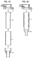
- Fig. 4A the case is separated into the circuit case 9 with the connector and the coil portion case 5.
- the coil portion case 5 a portion which is to be forced into the side core 7 is made to have a diameter smaller than the inner diameter of the side core 7, whereby it becomes possible to assemble the coil portion case 5, the side core 7 and the circuit case 9 in this order.
- the case is separated into a case 17 obtained by integrally forming both of the circuit with the connector and the coil portion and a case 18 only for a side of a high voltage portion.
- a portion which is to be forced into the side core 7 is made to have a diameter smaller than the inner diameter of the side core 7, whereby it becomes possible to assemble the circuit-and-coil integrating case 17, the side core 7 and the high voltage case 18 in this order.
- Fig. 4C the case is separated into the circuit case 9 with the connector, an intermediate portion case 19 in which the coil is inserted, and a case 18 only for the side of the high voltage portion.
- a part which is to be forced into the high pressure case 18 is made to have a diameter smaller than the inner diameter of the side core 7, and another part thereof which is to be forced into the circuit case 9 is made to have a diameter larger than the outer diameter of the side core, whereby it becomes possible to assemble the intermediate portion case 19, the side core 7, the high pressure case 18 and the circuit case 9 in this order.
- Fig. 4D the case is separated into the circuit case 9 with the connector and the coil portion case, and the coil portion case is molded by an injection molding or the like while inserting the side core 7, whereby it is possible to assemble a case 20 with the side core 7 and the circuit case 9 in this order.
- the forming process can be performed by winding the silicon steel strip around the jig, so that the productivity can be improved. Further, since the spirally wound cylindrical shape is adopted and since the space factor can be increased, it is possible to improve the flux density. In this case, when the same flux density is needed, the structure can be made further compact. Further, since it is possible to reduce the number of the parts in the side core, the number of the steps of the assembling process can be reduced.
- Fig. 5 shows an embodiment of a center core formed in accordance with the invention.
- the center core 6 is formed to have a spirally wound, cylindrical shape by steps of preparing a thin film amorphous silicon steel strip of not more than 0.1 mm in thickness (which was produced by Nippon Hishohshitu Company, Ltd. under the name of Amorphous 2605 TCA) or a crystallized silicon steel strip of not more than 0.23 mm in thickness, each of which amorphous and crystallized strips has a flux density 1.4T or more at a direct current magnetizing force of 800 A/m when measured in compliance with the direct current magnetizing characteristic test prescribed in JIS C2250, Paragraph 7.2, and winding the material around a jig or the like.
- a round bar iron core 14A of 4 to 8 mm in diameter made of a pure iron or a magnetic mild steel bar or the like is provided at a center portion of the center core, and the above-described amorphous silicon steel strip or the crystallized silicon steel strip described above is wound therearound, whereby a composite bar-like core 15 finally having an outer diameter between about 6 and about 10 mm is obtained which has a spirally wound portion around a solid portion.
- a jig having a size between about 1 and 8 mm is used, the amorphous or crystallized silicon steel strip described above being wound therearound, thereafter the jig is pulled out to thereby form a spirally wound, cylindrical core 15A having an outer diameter of about 6 to 10 mm, which core 15A has a hollow portion of 4 to 8 mm in diameter in the center portion of the center core.
- a flat rolled magnetic steel strip of the sandwiched structure described above which was produced by Nippon Kokan Company Ltd. is used, in which strip a 3% silicon portion 14 is located in the center portion thereof and 6.5% silicon portions 15 are located at the surface portions thereof so as to obtain the sandwich structure, thereby improving a workability and enabling to work the strip into the spiral shape.
- the product can be formed by winding it around the jig or the like, thereby improving the productivity.
- the product because of the increasing of the space factor thereof, it is possible to improve an efficiency of converting a magnetic flux.
- the invention it is possible to improve the productivity by the core of the spirally wound, cylindrical shape. Further, according to the invention, it is possible to raise the space factor of the center and side cores formed for a stick-shaped ignition coil to be fitted in an ignition plug-mounting hole, whereby it is possible to improve the flux density. On the other hand, in the case of the same flux density, it is possible to obtain a further compact structure. Further, since it is possible to reduce the number of the parts in the center core and the side core, it is possible to reduce the number of the steps of assembling process.
Landscapes
- Engineering & Computer Science (AREA)
- Chemical & Material Sciences (AREA)
- Combustion & Propulsion (AREA)
- Mechanical Engineering (AREA)
- General Engineering & Computer Science (AREA)
- Ignition Installations For Internal Combustion Engines (AREA)
Applications Claiming Priority (4)
| Application Number | Priority Date | Filing Date | Title |
|---|---|---|---|
| JP11175035A JP2001006953A (ja) | 1999-06-22 | 1999-06-22 | 内燃機関用点火装置 |
| JP17503599 | 1999-06-22 | ||
| JP11191202A JP2001023838A (ja) | 1999-07-06 | 1999-07-06 | 内燃機関用点火装置 |
| JP19120299 | 1999-07-06 |
Publications (2)
| Publication Number | Publication Date |
|---|---|
| EP1063425A2 true EP1063425A2 (de) | 2000-12-27 |
| EP1063425A3 EP1063425A3 (de) | 2002-09-25 |
Family
ID=26496428
Family Applications (1)
| Application Number | Title | Priority Date | Filing Date |
|---|---|---|---|
| EP00110130A Withdrawn EP1063425A3 (de) | 1999-06-22 | 2000-05-11 | Zündvorrichtung für Brennkraftmaschine |
Country Status (2)
| Country | Link |
|---|---|
| US (1) | US6474322B1 (de) |
| EP (1) | EP1063425A3 (de) |
Cited By (4)
| Publication number | Priority date | Publication date | Assignee | Title |
|---|---|---|---|---|
| GB2389237A (en) * | 2002-05-31 | 2003-12-03 | Denso Corp | Insulating resin encapsulating ignition coils and an igniter |
| EP1561943A3 (de) * | 2004-02-03 | 2007-07-11 | Delphi Technologies, Inc. | Kreisförmige Zündspulenanordnung |
| WO2008081211A1 (en) * | 2007-01-02 | 2008-07-10 | Ilija Andelic | Eco fuel saver for vehicle |
| WO2015071030A1 (de) * | 2013-11-14 | 2015-05-21 | Robert Bosch Gmbh | Elektronikmodul für eine zündeinheit |
Families Citing this family (5)
| Publication number | Priority date | Publication date | Assignee | Title |
|---|---|---|---|---|
| DE10152177A1 (de) * | 2001-10-23 | 2003-04-30 | Bosch Gmbh Robert | Stabspule für Zündanlagen |
| US7148780B2 (en) | 2005-01-24 | 2006-12-12 | Delphi Technologies, Inc. | Twin spark pencil coil |
| US7332991B2 (en) * | 2005-01-24 | 2008-02-19 | Delphi Technologies, Inc. | Twin spark ignition coil with provisions to balance load capacitance |
| DE102005028814A1 (de) * | 2005-06-22 | 2007-01-04 | Robert Bosch Gmbh | Zündspule für eine Brennkraftmaschine |
| US7445001B2 (en) * | 2006-06-15 | 2008-11-04 | Group Dekko Inc | Coil-on-plug ignition terminal |
Citations (1)
| Publication number | Priority date | Publication date | Assignee | Title |
|---|---|---|---|---|
| JPH0833523A (ja) | 1994-07-26 | 1996-02-06 | Matsushita Electric Works Ltd | 配膳車 |
Family Cites Families (7)
| Publication number | Priority date | Publication date | Assignee | Title |
|---|---|---|---|---|
| DE1764307A1 (de) * | 1967-05-15 | 1972-03-30 | Nippon Denso Co | Eisenkern fuer die Zuendspule eines Motorfahrzeugs |
| GB2105522A (en) * | 1981-09-05 | 1983-03-23 | Gen Motors Ltd | Laminated core structure |
| JPH02228011A (ja) * | 1989-03-01 | 1990-09-11 | Tdk Corp | トランス |
| JP3165000B2 (ja) * | 1995-04-21 | 2001-05-14 | 株式会社日立製作所 | 内燃機関用点火装置 |
| JPH09167711A (ja) * | 1995-12-14 | 1997-06-24 | Aisan Ind Co Ltd | 内燃機関用点火コイル |
| JP3165017B2 (ja) * | 1995-12-15 | 2001-05-14 | 株式会社日立製作所 | 内燃機関用点火装置 |
| EP0796993B1 (de) * | 1996-03-21 | 2003-07-09 | Hitachi, Ltd. | Zündapparat für eine Brennkraftmaschine |
-
2000
- 2000-05-11 EP EP00110130A patent/EP1063425A3/de not_active Withdrawn
- 2000-05-16 US US09/571,982 patent/US6474322B1/en not_active Expired - Fee Related
Patent Citations (1)
| Publication number | Priority date | Publication date | Assignee | Title |
|---|---|---|---|---|
| JPH0833523A (ja) | 1994-07-26 | 1996-02-06 | Matsushita Electric Works Ltd | 配膳車 |
Cited By (7)
| Publication number | Priority date | Publication date | Assignee | Title |
|---|---|---|---|---|
| GB2389237A (en) * | 2002-05-31 | 2003-12-03 | Denso Corp | Insulating resin encapsulating ignition coils and an igniter |
| GB2389237B (en) * | 2002-05-31 | 2006-03-08 | Denso Corp | Improvements in and relating to ignition coils |
| US7084729B2 (en) | 2002-05-31 | 2006-08-01 | Denso Corporation | Ignition coil |
| EP1561943A3 (de) * | 2004-02-03 | 2007-07-11 | Delphi Technologies, Inc. | Kreisförmige Zündspulenanordnung |
| WO2008081211A1 (en) * | 2007-01-02 | 2008-07-10 | Ilija Andelic | Eco fuel saver for vehicle |
| WO2015071030A1 (de) * | 2013-11-14 | 2015-05-21 | Robert Bosch Gmbh | Elektronikmodul für eine zündeinheit |
| CN105706538A (zh) * | 2013-11-14 | 2016-06-22 | 罗伯特·博世有限公司 | 用于点火单元的电子模块 |
Also Published As
| Publication number | Publication date |
|---|---|
| US6474322B1 (en) | 2002-11-05 |
| EP1063425A3 (de) | 2002-09-25 |
Similar Documents
| Publication | Publication Date | Title |
|---|---|---|
| EP0738831B1 (de) | Zündspule für eine innere Brennkraftmaschine | |
| US4392072A (en) | Dynamoelectric machine stator having articulated amorphous metal components | |
| US5088186A (en) | Method of making a high efficiency encapsulated power transformer | |
| JP2535094B2 (ja) | 点火コイル | |
| US5268663A (en) | Ignition coil assembly directly applied to ignition plug for internal combustion engine | |
| US20060130314A1 (en) | Method for manufacturing a stator core for a dynamoelectric machine | |
| US6650221B2 (en) | Ignition coil for an internal combustion engine | |
| JPH09320865A (ja) | 内燃機関用点火コイル | |
| US6474322B1 (en) | Ignition device for internal combustion engine | |
| JPH09186029A (ja) | 内燃機関用点火コイル | |
| EP0827164A3 (de) | Zündspulenvorrichtung für Brennkraftmaschine und Verfahren zum Wickeln einer Zündspule | |
| US4985984A (en) | Ignition coil for internal combustion engine | |
| US7239224B2 (en) | Ignition coil having center core | |
| JPH097860A (ja) | 内燃機関用点火コイル | |
| JP3671171B2 (ja) | コイル装置及びその製造方法 | |
| JPH0636950A (ja) | 内燃機関用点火コイルの磁心 | |
| JP2001023838A (ja) | 内燃機関用点火装置 | |
| JP3274997B2 (ja) | 内燃機関用点火コイル | |
| JPS5976409A (ja) | インダクタの製造方法 | |
| JPH09167711A (ja) | 内燃機関用点火コイル | |
| JPH0654495A (ja) | 分割型鉄芯の樹脂モールド方法 | |
| JPH09167710A (ja) | 内燃機関用点火コイル | |
| JPS59191314A (ja) | 内燃機関用点火コイル | |
| JP2002170727A (ja) | 点火コイル用鉄芯の製造方法 | |
| JPH09213543A (ja) | 内燃機関用点火コイル |
Legal Events
| Date | Code | Title | Description |
|---|---|---|---|
| PUAI | Public reference made under article 153(3) epc to a published international application that has entered the european phase |
Free format text: ORIGINAL CODE: 0009012 |
|
| AK | Designated contracting states |
Kind code of ref document: A2 Designated state(s): AT BE CH CY DE DK ES FI FR GB GR IE IT LI LU MC NL PT SE |
|
| AX | Request for extension of the european patent |
Free format text: AL;LT;LV;MK;RO;SI |
|
| PUAL | Search report despatched |
Free format text: ORIGINAL CODE: 0009013 |
|
| AK | Designated contracting states |
Kind code of ref document: A3 Designated state(s): AT BE CH CY DE DK ES FI FR GB GR IE IT LI LU MC NL PT SE |
|
| AX | Request for extension of the european patent |
Free format text: AL;LT;LV;MK;RO;SI |
|
| 17P | Request for examination filed |
Effective date: 20030124 |
|
| 17Q | First examination report despatched |
Effective date: 20030415 |
|
| AKX | Designation fees paid |
Designated state(s): DE FR GB IT |
|
| STAA | Information on the status of an ep patent application or granted ep patent |
Free format text: STATUS: THE APPLICATION IS DEEMED TO BE WITHDRAWN |
|
| 18D | Application deemed to be withdrawn |
Effective date: 20031028 |