EP1063473B1 - Appareil à combustion et four de fusion pour métaux non-ferreux - Google Patents
Appareil à combustion et four de fusion pour métaux non-ferreux Download PDFInfo
- Publication number
- EP1063473B1 EP1063473B1 EP00113290A EP00113290A EP1063473B1 EP 1063473 B1 EP1063473 B1 EP 1063473B1 EP 00113290 A EP00113290 A EP 00113290A EP 00113290 A EP00113290 A EP 00113290A EP 1063473 B1 EP1063473 B1 EP 1063473B1
- Authority
- EP
- European Patent Office
- Prior art keywords
- burner
- burner group
- furnace
- fired
- air
- Prior art date
- Legal status (The legal status is an assumption and is not a legal conclusion. Google has not performed a legal analysis and makes no representation as to the accuracy of the status listed.)
- Expired - Lifetime
Links
- 238000002485 combustion reaction Methods 0.000 title claims description 56
- 238000002844 melting Methods 0.000 title claims description 45
- 230000008018 melting Effects 0.000 title claims description 45
- 229910052751 metal Inorganic materials 0.000 title claims description 42
- 239000002184 metal Substances 0.000 title claims description 42
- 150000002739 metals Chemical class 0.000 title claims description 20
- 239000000446 fuel Substances 0.000 claims description 45
- 239000002918 waste heat Substances 0.000 claims description 30
- 230000001276 controlling effect Effects 0.000 claims description 12
- 230000001105 regulatory effect Effects 0.000 claims description 12
- 239000007788 liquid Substances 0.000 claims description 8
- 238000010304 firing Methods 0.000 claims description 4
- 238000000034 method Methods 0.000 claims description 4
- 230000008569 process Effects 0.000 claims description 4
- -1 ferrous metals Chemical class 0.000 claims 4
- 239000000567 combustion gas Substances 0.000 description 15
- 238000009434 installation Methods 0.000 description 14
- 229910001338 liquidmetal Inorganic materials 0.000 description 14
- 230000001172 regenerating effect Effects 0.000 description 8
- 230000004907 flux Effects 0.000 description 6
- 238000012423 maintenance Methods 0.000 description 6
- 239000007800 oxidant agent Substances 0.000 description 6
- 230000001590 oxidative effect Effects 0.000 description 6
- 229910052782 aluminium Inorganic materials 0.000 description 5
- XAGFODPZIPBFFR-UHFFFAOYSA-N aluminium Chemical compound [Al] XAGFODPZIPBFFR-UHFFFAOYSA-N 0.000 description 5
- 238000010276 construction Methods 0.000 description 5
- 238000010438 heat treatment Methods 0.000 description 5
- 230000007423 decrease Effects 0.000 description 4
- 239000000203 mixture Substances 0.000 description 4
- RYGMFSIKBFXOCR-UHFFFAOYSA-N Copper Chemical compound [Cu] RYGMFSIKBFXOCR-UHFFFAOYSA-N 0.000 description 2
- HCHKCACWOHOZIP-UHFFFAOYSA-N Zinc Chemical compound [Zn] HCHKCACWOHOZIP-UHFFFAOYSA-N 0.000 description 2
- 230000008901 benefit Effects 0.000 description 2
- 230000008859 change Effects 0.000 description 2
- 229910052802 copper Inorganic materials 0.000 description 2
- 239000010949 copper Substances 0.000 description 2
- 238000004519 manufacturing process Methods 0.000 description 2
- 239000000155 melt Substances 0.000 description 2
- 229910044991 metal oxide Inorganic materials 0.000 description 2
- 150000004706 metal oxides Chemical class 0.000 description 2
- 238000013021 overheating Methods 0.000 description 2
- TWNQGVIAIRXVLR-UHFFFAOYSA-N oxo(oxoalumanyloxy)alumane Chemical compound O=[Al]O[Al]=O TWNQGVIAIRXVLR-UHFFFAOYSA-N 0.000 description 2
- 239000011701 zinc Substances 0.000 description 2
- 229910052725 zinc Inorganic materials 0.000 description 2
- ATJFFYVFTNAWJD-UHFFFAOYSA-N Tin Chemical compound [Sn] ATJFFYVFTNAWJD-UHFFFAOYSA-N 0.000 description 1
- 238000009825 accumulation Methods 0.000 description 1
- 229910045601 alloy Inorganic materials 0.000 description 1
- 239000000956 alloy Substances 0.000 description 1
- 230000009467 reduction Effects 0.000 description 1
- 229910052718 tin Inorganic materials 0.000 description 1
- 239000011135 tin Substances 0.000 description 1
Images



Classifications
-
- F—MECHANICAL ENGINEERING; LIGHTING; HEATING; WEAPONS; BLASTING
- F27—FURNACES; KILNS; OVENS; RETORTS
- F27B—FURNACES, KILNS, OVENS OR RETORTS IN GENERAL; OPEN SINTERING OR LIKE APPARATUS
- F27B3/00—Hearth-type furnaces, e.g. of reverberatory type; Electric arc furnaces ; Tank furnaces
- F27B3/10—Details, accessories or equipment, e.g. dust-collectors, specially adapted for hearth-type furnaces
- F27B3/26—Arrangements of heat-exchange apparatus
- F27B3/263—Regenerators
-
- F—MECHANICAL ENGINEERING; LIGHTING; HEATING; WEAPONS; BLASTING
- F23—COMBUSTION APPARATUS; COMBUSTION PROCESSES
- F23L—SUPPLYING AIR OR NON-COMBUSTIBLE LIQUIDS OR GASES TO COMBUSTION APPARATUS IN GENERAL ; VALVES OR DAMPERS SPECIALLY ADAPTED FOR CONTROLLING AIR SUPPLY OR DRAUGHT IN COMBUSTION APPARATUS; INDUCING DRAUGHT IN COMBUSTION APPARATUS; TOPS FOR CHIMNEYS OR VENTILATING SHAFTS; TERMINALS FOR FLUES
- F23L15/00—Heating of air supplied for combustion
- F23L15/02—Arrangements of regenerators
-
- Y—GENERAL TAGGING OF NEW TECHNOLOGICAL DEVELOPMENTS; GENERAL TAGGING OF CROSS-SECTIONAL TECHNOLOGIES SPANNING OVER SEVERAL SECTIONS OF THE IPC; TECHNICAL SUBJECTS COVERED BY FORMER USPC CROSS-REFERENCE ART COLLECTIONS [XRACs] AND DIGESTS
- Y02—TECHNOLOGIES OR APPLICATIONS FOR MITIGATION OR ADAPTATION AGAINST CLIMATE CHANGE
- Y02E—REDUCTION OF GREENHOUSE GAS [GHG] EMISSIONS, RELATED TO ENERGY GENERATION, TRANSMISSION OR DISTRIBUTION
- Y02E20/00—Combustion technologies with mitigation potential
- Y02E20/34—Indirect CO2mitigation, i.e. by acting on non CO2directly related matters of the process, e.g. pre-heating or heat recovery
Definitions
- the present invention relates to a melting furnace, which includes a continuous furnace and a batch-type furnace, for melting nonferrous metals such as copper, aluminum, zinc and alloy, which comprises more than one pair of regenerative burners where waste heat produced by a first burner is stored in a regenerator of a second burner and the stored waste heat is utilized when the second burner is fired.
- a melting furnace which includes a continuous furnace and a batch-type furnace, for melting nonferrous metals such as copper, aluminum, zinc and alloy, which comprises more than one pair of regenerative burners where waste heat produced by a first burner is stored in a regenerator of a second burner and the stored waste heat is utilized when the second burner is fired.
- the apparatus comprises a regenerative burner including a pair of burners 19, 20.
- the burners 19, 20 are fired alternately as such that when a first burner 19 is fired, a second burner 20 stores waste heat produced by the first burner 19, and the stored waste heat is used to preheat the combustion air of the burner 20 when the second burner 20 is fired.
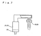
- the conventional combustion apparatus comprises one regenerator 21 or 22 per one burner 19 or 20, so that, for example, when there are provided eight (four pairs of) burners, the same number, eight, of regenerators need to be installed.
- the conventional combustion apparatus comprises a regulating valve 23 at the upper stream of the regenerator 3 for controlling a volume of combustion air. With an operation of the regulating valve 23, the combustion of the burner 19 or 20 is to be controlled.
- the regenerative burner comprises a pair of burners, each of which is fired alternately as such that when a first burner is fired, a second burner stores waste heat produced by the first burner. The stored waste heat is used to preheat the combustion air of the second burner when the second burner is fired.
- the conventional melting furnace for nonferrous metals will be described in detail referring to Figs. 8 and 9.
- the melting furnace comprises a pair of regenerative burners 16, 17, at the side wall 5a of the furnace casing 5, and each burner 16 or 17 is integrated with a regenerator.
- This melting furnace operates as such that while a first burner 16 is fired, a second burner 17 is unfired but stores the waste heat produced by the first burner 16, as the waste heat is exhausted through a regenerator of the second burner 17. And, when the second burner 17 is fired, combustion air is provided through the regenerator of the second burner 17 and is preheated by the stored waste heat. By use of the waste heat, a thermal efficiency of the burners 16, 17 increases.
- each burner 19 or 20 is equipped with its own regenerator 21 or 22, so that when a large number of burners 19, 20 require to be installed in, for example, a continuous furnace 18, the same number of regenerators 21, 22 should also be installed. Therefore, the conventional combustion apparatus requires a much installation space as well as much cost and labor for an installation of the regenerators 21, 22 and a maintenance engineering thereof.
- each burner 16 or 17 is integrated with its own regenerator and is installed in the side wall 5a of the furnace casing 5. Therefore, an installation space and size of the burners 16, 17 becomes restricted, and as a result of this, a quantity and capacity of the burners 16, 17 are also restricted. Besides, it becomes necessary to enlarge the furnace casing 5 in its size, which induces a higher construction cost.
- the conventional melting furnace is provided with a metal feeding device 14 for feeding aluminum, e.g., as well as an auxiliary apparatus 15, for example a pump, for circulation of the liquid metal at the side wall 5a of the furnace casing 5, in addition to the burners 16, 17 combined with the regenerators, an installation space of the burners 16, 17 is severely restricted. This becomes crucial when the furnace casing 5 is smaller in size. In such a case, it becomes necessary to select limited types of burners among many to install in the restricted small installation space. Also, a number of the burners to be installed is restricted. As a result of this, the burners 16, 17 tend to become unsatisfactory in capacity for efficiently melting and heating the nonferrous metal held in the furnace.
- the conventional melting furnace for nonferrous metals comprises the burners 16, 17 at the side wall 5a of the furnace casing 5, when the burners 16, 17 are fired, the combustion gas runs onto the surface of the liquid metal 40 in the nearly horizontal angle. Thus, the combustion gas does not wide spread over the surface of the liquid metal 40, heating only a local area of the surface. Besides, the jet flow of the combustion gas impinges on a certain area of the side wall 5a of the furnace. The certain area of the side wall 5a, where the jet flow of the combustion gas impinges on, becomes extremely high in temperature and a mass of nonferrous metal oxide 30 is produced thereabout and is ingrained and accumulated to the side wall 5a.
- US-A-5,823,769 discloses a melting furnace according to the preamble of claim 1.
- a first portion of a fuel is mixed with an oxidant to form a fuel-lean fuel/oxidant mixture in a fuel-lean combustion zone.
- the remaining portion of the fuel is mixed with the fuel-lean fuel/oxidant mixture downstream of the fuel-lean combustion zone, forming a substantially stoichiometric fuel/oxidant mixture.
- the stoichiometric fuel/oxidant mixture is ignited, forming a primary flame having high luminosity and low NO x emissions.
- It is an object of the present invention to provide a melting furnace for nonferrous metals comprising burners combined with regenerators on the roof of the furnace in order not to restrict the size, disposition and installation space of the burners, which will increase a heat transfer efficiency, save a construction cost and a production of oxide as well as an increase in a life duration of the side wall 5a and a reduction of maintenance cost.
- the object is achieved by the furnace according to the melting furnace of claim 1, as well as by the process of claim 3.
- the combustion apparatus comprises a regulating valve for controlling a volume of combustion air.
- the valve is installed on the side of each burner.
- High velocity jet flame or combustion gas ejected from each burner is directed right below to impinge on the nonferrous metal or the surface of the liquid metal in the furnace to transfer the heat.
- the melting furnace for nonferrous metals comprises a primary fuel supplying system and a secondary fuel supplying system, as well as a whole required combustion air supplying system.
- Each burner group is installed on the roof of the furnace as distanced from each other.
- a supplying ratio of the primary fuel and the secondary fuel is regulated to control the combustion in the furnace for the purpose of controlling the variation of flame and for controlling the temperature distribution in the furnace.
- a melting furnace for nonferrous metals comprises a primary fuel supplying system and a secondary fuel supplying system, as well as a whole required combustion air supplying system.
- Each burner group is installed on the roof of the furnace as distanced from each other.
- a supplying ratio of the primary fuel and the secondary fuel is regulated to control the combustion in the furnace for the purpose of shifting or varying the heat flux and for varying or evening the temperature fields in the furnace.
- regenerator per a plurality of burners. Therefore, it is possible to drastically save an installation space, cost and labor for installation and the maintenance engineering of regenerators.
- each burner is provided with a regulating valve for controlling a volume of a combustion air. Therefore, it becomes possible to control a combustion volume of each individual burner to accurately control the temperature of the furnace or melting furnace.
- each group of burners is installed on the roof of a furnace and they eject high velocity jet flame or combustion gas directly below the roof. Therefore, it is possible to install a desired type of burners. That is, no auxiliary apparatus but a wide space is provided above the furnace casing, so that a desired number and type of burners are selected and installed without any restrictions. Accordingly, it is possible to properly melt the nonferrous metal in the furnace and hold the metal in a liquid form. Because of such advantage, there is no need to enlarge the furnace casing, thus saving a construction cost and labor.
- the high velocity jet flame or combustion gas ejected from the burners impinges on the liquid metal surface at right angles, they spread all over the surface of the liquid metal, evenly heating the whole liquid metal and preventing any local area from overheating. Therefore, a generation of oxide is restrained and the decrease in the yield of melting is improved. Further, jet flows of the combustion gas evenly flow toward a side wall, so that the oxide does not accumulate at a specific area of the side wall. Therefore, the drawback regarding to a decrease of the life duration of the furnace is improved.
- a combustion volume of each burner group is controlled by adjusting a primary fuel and secondary fuel so as to shift or vary the heat flux in the vertical and horizontal directions and to vary or even the temperature fields in the furnace. Therefore, it becomes possible to maintain the inside of the furnace a properly desirable condition.
- Fig. 1 is a schematic plane view illustrating a combustion apparatus.
- the combustion apparatus comprises a plurality of regenerative burner groups, and each regenerative burner group comprises one regenerator 3 or 4 per four burners 1a, 1b, 1c, 1d or 2a, 2b, 2c, 2d. Two regenerative burner groups 1, 2 make a pair, and each group is fired alternately.
- a regenerator 4 of a second burner group 2 stores waste heat produced by the first group 1, and the stored waste heat is utilized to preheat the combustion air of the second burner group when the second burner group 2 is fired.
- the combustion apparatus comprises three pairs of burner groups, which are six burner groups, and they are installed in a continuous furnace 18.
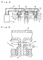
- a regulating valve 13 for controlling a volume of combustion air is provided at each burner side (see the regulating valve in Figs. 4 and 5).
- the other burner group 2 (a second burner group) is kept unfired but stores waste heat produced by the first burner group 1 in a regenerator 4 of the second burner group.
- the stored waste heat is utilized to preheat the combustion air of the second burner group 2.
- combustion air is preheated, thus each of the burners 1a to 2d are efficiently fired.
- the waste heat produced by the second burner group 2 is stored in a regenerator of the first burner group 1, and it is utilized to preheat the combustion air of the first burner group 1 when the first burner group 1 is fired.
- the combustion apparatus comprises one regenerator 3 or 4 per four burners 1a-1d or 2a-2d, so that it becomes possible to reduce an installation space of the apparatus. It is also possible to drastically reduce a cost and labor needed for installation and a maintenance engineering of the regenerator 3, 4.
- a regulating valve 13 for controlling a volume of combustion air is secured on the side of each burner 1a-2d, so that an individual control of a combustion volume of each burner becomes possible.
- the combustion apparatus in this embodiment is installed in a continuous furnace 18 though it may be installed in other types of furnaces including a batch-type furnace as well as in various types of melting furnaces and other existing facilities.
- FIG. 2 is a schematic plane view illustrating a melting furnace for nonferrous metals.
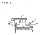
- Fig. 3 is a schematic sectional view along line A-A in Fig. 1. Same numerals are applied to portions identical to the portions shown in the prior art.
- An embodiment of a melting furnace for nonferrous metals comprises a pair of burner groups 1, 2, where each group 1 or 2 is fired alternately. Waste heat produced by a first burner group while the same is fired is stored in a regenerator 4 of a second burner group 2, and the stored waste heat is utilized to preheat the combustion air of the second burner group 2 when the second burner group 2 is fired.
- the melting furnace melts a nonferrous metal or heats the metal to hold it in a liquid form in a furnace.
- a pair of burner groups 1, 2 are installed on the roof of the furnace casing 5. Burners of each group 1, 2 eject high velocity jet flame or combustion gas down to the upper surface of the nonferrous metal or liquid metal and transfer the heat efficiently thereto.
- the nonferrous metal in the furnace in this embodiment is aluminum, but other nonferrous metals such as copper, zinc, tin or the like may be held and melted in the furnace.
- Each burner group 1 or 2 comprises three burners 1a-1c or 2a-2c respectively, and each three burners 1a-1c or 2a-2c are connected in series by a connecting duct 6 or 7 and communicates to an corresponding regenerator 3 or 4 which are installed nearby the side wall 5a of the furnace casing 5.
- Each connecting duct 6 or 7 is interconnected with an expansion joint 6a or 7a in order to expand or contract corresponding to the high temperature heat.
- all the burner groups 1, 2 are installed on the roof of the furnace casing 5, therefore, it is possible to obtain a wider installation space for the burners.
- the aluminum oxide 30 does not accumulate at a specific portion of the side wall 5a. Also, the combustion gas does not impinge on a specific portion of the side wall 5a. Therefore, a life duration of the furnace drastically lengthens.
- the melting furnace for nonferrous metals, there are provided three burners 1a-2c in each burner group 1 or 2 on the roof of the furnace casing 5, and there is provided, a certain distance between adjacent burners.
- This melting furnace has such functions: it enables to optimize the heat flux in the furnace by controlling a combustion volume of each burner 1a-2c; it also enables to vary and even the temperature fields in the furnace by moving or shifting the heat flux in the vertical and horizontal directions.
- each burner group 1 or 2 comprises an air nozzle 9 communicated with a primary fuel nozzle 10 in a burner tile 8, as well as a plurality of secondary fuel nozzles 11, 11 arranged in parallel nearby the port of the air nozzle 9.
- a pilot burner 12 for ignition and a regulating valve 13 for controlling a volume of combustion air are also provided.
- the air in the air nozzle 9 and the fuel supplied from the primary fuel nozzle 10 are fired in the burner tile 8.
- the air in the air nozzle 9 and the fuel supplied from the secondary fuel nozzle 11 are combined and fired in the furnace.
- the first and second systems are combined. Any combustion system out of three systems is selectively chosen. Further, by controlling a supplying ratio of the primary fuel and the secondary fuel for combustion, it becomes possible to selectively vary the flame to control a temperature distribution in the furnace.
- the primary fuel is supplied from the primary fuel nozzle 10, and the secondary fuel is supplied from the secondary fuel nozzle 11. Accordingly, it is possible to fire each burner group 1 or 2 as desired for a purpose of maintaining the furnace a preferable condition.
- regenerator per a plurality of burners. Therefore, it is possible to drastically save an installation space, cost and labor for installation and the maintenance engineering of regenerators. This prominently increases productivity of the apparatus.
- each burner is provided with a regulating valve for controlling a volume of combustion air. Therefore, it becomes possible to control a combustion volume of each individual burner to accurately control the temperature of the furnace or melting furnace. This also increases productivity of the apparatus.
- a group of burners are installed on the roof of a furnace casing and they eject high velocity jet flame or combustion gas directly below the roof. Therefore, it is possible to install a desired type of burners. That is, no auxiliary apparatus but a wide space is provided above the furnace casing, so that a desired number and type of burners are selected and installed without any restrictions.
- the high velocity jet flame or combustion gas ejected from the burners impinges on the liquid metal surface at right angles, they spread all over the surface of the liquid metal, evenly heating the whole liquid metal and preventing any local area from overheating.
- a combustion volume of each burner group is controlled by adjusting a primary fuel and secondary fuel so as to shift or vary the heat flux in the vertical and horizontal directions and to vary or even the temperature fields in the furnace. Therefore, it becomes possible to maintain the inside of the furnace a properly desirable condition.
Landscapes
- Engineering & Computer Science (AREA)
- Mechanical Engineering (AREA)
- General Engineering & Computer Science (AREA)
- Chemical & Material Sciences (AREA)
- Combustion & Propulsion (AREA)
- Vertical, Hearth, Or Arc Furnaces (AREA)
- Air Supply (AREA)
- Waste-Gas Treatment And Other Accessory Devices For Furnaces (AREA)
Claims (4)
- Four de fusion (18) pour les métaux non ferreux permettant de faire fondre tous les métaux non ferreux et permettant de maintenir le métal sous une forme liquide, comprenant un appareil à combustion comprenant une paire ou plus de deux paires de groupes brûleurs (1, 2) ; chaque groupe brûleur (1, 2) comprend un régénérateur (3, 4) pour une pluralité de brûleurs (1a-1d, 2a-2d) et lesdits groupes brûleurs (1, 2) sont installés sur le toit du four (18) à distance les uns des autres ; l'appareil à combustion comprend des moyens pour allumer un premier groupe brûleur (1) et un second groupe brûleur (2) de manière alternée, des moyens pour stocker la chaleur perdue produite lorsque ledit premier groupe brûleur (1) est allumé dans un régénérateur (4) du second groupe brûleur (2), des moyens pour utiliser ladite chaleur perdue stockée pour préchauffer l'air de combustion dudit second groupe brûleur (2) lorsque ledit second groupe brûleur (2) est allumé ; de manière similaire, des moyens pour stocker la chaleur perdue produite lorsque ledit second groupe brûleur (2) est allumé dans un régénérateur (3) du premier groupe brûleur (1), des moyens pour utiliser ladite chaleur perdue stockée pour préchauffer l'air de combustion dudit premier groupe brûleur (1) lorsque ledit premier groupe brûleur (1) est allumé, caractérisé en ce que :chaque groupe brûleur (1, 2) comprend une buse d'air (9) qui communique avec une buse de carburant principale (10) dans une brique (8) de brûleur, ainsi qu'une pluralité de buses de carburant secondaires (11) agencées parallèlement à proximité de l'orifice de la buse d'air (9) ;l'on prévoit trois systèmes de combustion :des moyens pour enflammer l'air dans la buse d'air (9) et le carburant alimenté à partir de la buse de carburant principale (10) dans la brique (8) de brûleur ;des moyens pour combiner l'air dans la buse d'air (9) et le carburant alimenté à partir de la buse de carburant secondaire (11) et pour les enflammer dans le four (18) ; etdes moyens pour combiner les premier et second systèmes.
- Four de fusion selon la revendication 1, caractérisé en ce qu'une soupape de régulation (13) pour réguler un volume d'air de combustion, est installée sur le côté de chaque brûleur (1a-d, 2a-d).
- Procédé pour faire fondre des métaux non ferreux et pour maintenir les métaux sous une forme liquide en utilisant un four de fusion (18) selon la revendication 1 ou 2, dans lequel un premier groupe brûleur (1) et un second groupe brûleur (2) sont allumés de manière alternée, dans lequel la chaleur perdue produite lorsque ledit premier groupe brûleur (1) est allumé, est stockée dans un régénérateur (4) du second groupe brûleur (2), ladite chaleur perdue stockée est utilisée pour préchauffer l'air de combustion dudit second groupe brûleur (2) lorsque ledit second groupe brûleur (2) est allumé, la chaleur perdue produite lorsque ledit second groupe brûleur (2) est allumé, est stockée dans un régénérateur (3) du premier groupe brûleur (1) ; ladite chaleur perdue stockée est utilisée pour préchauffer l'air de combustion dudit premier groupe brûleur (1) lorsque ledit premier groupe brûleur (1) est allumé, dans lequel l'air dans la buse d'air (9) et le carburant alimenté à partir de la buse de carburant principale (10) sont enflammés dans la brique (8) de brûleur, l'air dans la buse d'air (9) et le carburant alimenté à partir de la buse de carburant secondaire (11) sont combinés et enflammés dans le four (18) et l'on prévoit des moyens pour combiner les premier et second systèmes.
- Utilisation d'un four de fusion selon la revendication 1 ou 2 pour faire fondre des métaux non ferreux et pour maintenir les métaux sous une forme liquide.
Applications Claiming Priority (4)
| Application Number | Priority Date | Filing Date | Title |
|---|---|---|---|
| JP17935499 | 1999-06-25 | ||
| JP17935499 | 1999-06-25 | ||
| JP2000114936A JP3394500B2 (ja) | 1999-06-25 | 2000-04-17 | 非鉄金属溶解炉 |
| JP2000114936 | 2000-04-17 |
Publications (2)
| Publication Number | Publication Date |
|---|---|
| EP1063473A1 EP1063473A1 (fr) | 2000-12-27 |
| EP1063473B1 true EP1063473B1 (fr) | 2005-08-17 |
Family
ID=26499242
Family Applications (1)
| Application Number | Title | Priority Date | Filing Date |
|---|---|---|---|
| EP00113290A Expired - Lifetime EP1063473B1 (fr) | 1999-06-25 | 2000-06-21 | Appareil à combustion et four de fusion pour métaux non-ferreux |
Country Status (6)
| Country | Link |
|---|---|
| US (1) | US6495092B1 (fr) |
| EP (1) | EP1063473B1 (fr) |
| JP (1) | JP3394500B2 (fr) |
| KR (1) | KR100417156B1 (fr) |
| DE (1) | DE60021959T2 (fr) |
| ES (1) | ES2246204T3 (fr) |
Families Citing this family (7)
| Publication number | Priority date | Publication date | Assignee | Title |
|---|---|---|---|---|
| US7850448B2 (en) * | 2004-03-03 | 2010-12-14 | Beckett Gas, Inc. | Furnace |
| US7452400B2 (en) * | 2005-07-07 | 2008-11-18 | The North American Manufacturing Company, Ltd. | Method and apparatus for melting metal |
| US7648672B2 (en) * | 2007-05-17 | 2010-01-19 | Tempel Steel Company | Process and system employing generation of controlled furnace atmospheres without the use of separate gas supplies or stand-alone atmosphere generators |
| JP5203421B2 (ja) * | 2010-06-04 | 2013-06-05 | 中外炉工業株式会社 | 溶解炉 |
| US8740612B2 (en) * | 2010-06-30 | 2014-06-03 | Bryan Joseph Kraus | Regenerative firing system |
| PL3234071T3 (pl) * | 2014-12-17 | 2021-08-16 | Pilkington Group Limited | Piec |
| EP3722671B1 (fr) * | 2019-04-11 | 2021-10-06 | Hertwich Engineering GmbH | Procédé de chauffage continue de chambres de combustion à au moins trois brûleurs dégénératifs |
Family Cites Families (9)
| Publication number | Priority date | Publication date | Assignee | Title |
|---|---|---|---|---|
| US2354324A (en) * | 1941-06-18 | 1944-07-25 | Levi S Longenecker | Regenerative furnace and method of burning liquid fuel therein |
| GB2136553B (en) | 1983-03-11 | 1986-02-12 | British Gas Corp | Burner |
| US4923391A (en) * | 1984-08-17 | 1990-05-08 | American Combustion, Inc. | Regenerative burner |
| GB8507993D0 (en) * | 1985-03-27 | 1985-05-01 | Hotwork Ltd | Furnace heating |
| JP2638394B2 (ja) | 1992-06-05 | 1997-08-06 | 日本ファーネス工業株式会社 | 低NOx燃焼法 |
| FR2722272B1 (fr) * | 1994-07-08 | 1996-08-23 | Air Liquide | Ensemble de combustion pour un four et procede de mise en oeuvre |
| US5571006A (en) | 1995-07-24 | 1996-11-05 | Tokyo Gas Company, Ltd. | Regenerative burner, burner system and method of burning |
| WO1997027441A1 (fr) * | 1996-01-25 | 1997-07-31 | Frazier-Simplex, Inc. | Regeneration de chaleur pour fours chauffes a l'oxygene et au gaz combustible |
| US5823769A (en) * | 1996-03-26 | 1998-10-20 | Combustion Tec, Inc. | In-line method of burner firing and NOx emission control for glass melting |
-
2000
- 2000-04-17 JP JP2000114936A patent/JP3394500B2/ja not_active Expired - Fee Related
- 2000-06-21 US US09/598,734 patent/US6495092B1/en not_active Expired - Lifetime
- 2000-06-21 DE DE60021959T patent/DE60021959T2/de not_active Expired - Lifetime
- 2000-06-21 EP EP00113290A patent/EP1063473B1/fr not_active Expired - Lifetime
- 2000-06-21 ES ES00113290T patent/ES2246204T3/es not_active Expired - Lifetime
- 2000-06-24 KR KR10-2000-0035004A patent/KR100417156B1/ko not_active Expired - Fee Related
Also Published As
| Publication number | Publication date |
|---|---|
| JP3394500B2 (ja) | 2003-04-07 |
| KR20010007512A (ko) | 2001-01-26 |
| KR100417156B1 (ko) | 2004-02-05 |
| US6495092B1 (en) | 2002-12-17 |
| DE60021959T2 (de) | 2006-02-09 |
| ES2246204T3 (es) | 2006-02-16 |
| EP1063473A1 (fr) | 2000-12-27 |
| JP2001065859A (ja) | 2001-03-16 |
| DE60021959D1 (de) | 2005-09-22 |
Similar Documents
| Publication | Publication Date | Title |
|---|---|---|
| US6939130B2 (en) | High-heat transfer low-NOx combustion system | |
| TW491819B (en) | Method of boosting a glass melting furnace using a roof mounted oxygen-fuel burner | |
| KR101837832B1 (ko) | 축열로를 위한 선택형 산소-연료 부스트 버너 시스템 및 방법 | |
| US5934899A (en) | In-line method of burner firing and NOx emission control for glass melting | |
| JPH0597444A (ja) | ガラス溶融用の交差火炎型蓄熱炉における補助酸素バーナー技法 | |
| EP1138638B1 (fr) | Brûleur et procédé de combustion | |
| JP2001004128A (ja) | 高温炉の効率および生産性の向上方法およびシステム | |
| US6079229A (en) | Process for improving the thermal profile of glass ovens | |
| US5906119A (en) | Process and device for melting glass | |
| EP1063473B1 (fr) | Appareil à combustion et four de fusion pour métaux non-ferreux | |
| US3633886A (en) | Heating furnaces | |
| RU2215792C1 (ru) | Воздухонагреватель | |
| CN101993187A (zh) | 全氧燃烧用扁平式喷枪 | |
| US5855639A (en) | Process for the conversion of a glass furnace with the aid of a combustion with oxygen | |
| JP3608692B2 (ja) | るつぼ炉 | |
| JPH0694368A (ja) | 蓄熱式溶解炉およびその運転方法 | |
| US20260092703A1 (en) | Combustion furnace and assembly | |
| JP4670715B2 (ja) | 連続式加熱炉群の被加熱物の振り分け方法 | |
| EP1584694B1 (fr) | Four de type continu | |
| SU1280289A1 (ru) | Печь поверхностного горени | |
| JPH09303751A (ja) | マッフル炉 | |
| JPH10176826A (ja) | 蓄熱式バーナ | |
| CZ1701U1 (cs) | Sklářská tavicí pánvová pec |
Legal Events
| Date | Code | Title | Description |
|---|---|---|---|
| PUAI | Public reference made under article 153(3) epc to a published international application that has entered the european phase |
Free format text: ORIGINAL CODE: 0009012 |
|
| AK | Designated contracting states |
Kind code of ref document: A1 Designated state(s): DE ES FR GB |
|
| AX | Request for extension of the european patent |
Free format text: AL;LT;LV;MK;RO;SI |
|
| 17P | Request for examination filed |
Effective date: 20010425 |
|
| AKX | Designation fees paid |
Free format text: DE ES FR GB |
|
| 17Q | First examination report despatched |
Effective date: 20030813 |
|
| GRAP | Despatch of communication of intention to grant a patent |
Free format text: ORIGINAL CODE: EPIDOSNIGR1 |
|
| GRAS | Grant fee paid |
Free format text: ORIGINAL CODE: EPIDOSNIGR3 |
|
| GRAA | (expected) grant |
Free format text: ORIGINAL CODE: 0009210 |
|
| AK | Designated contracting states |
Kind code of ref document: B1 Designated state(s): DE ES FR GB |
|
| REG | Reference to a national code |
Ref country code: GB Ref legal event code: FG4D |
|
| REF | Corresponds to: |
Ref document number: 60021959 Country of ref document: DE Date of ref document: 20050922 Kind code of ref document: P |
|
| REG | Reference to a national code |
Ref country code: ES Ref legal event code: FG2A Ref document number: 2246204 Country of ref document: ES Kind code of ref document: T3 |
|
| PLBE | No opposition filed within time limit |
Free format text: ORIGINAL CODE: 0009261 |
|
| STAA | Information on the status of an ep patent application or granted ep patent |
Free format text: STATUS: NO OPPOSITION FILED WITHIN TIME LIMIT |
|
| 26N | No opposition filed |
Effective date: 20060518 |
|
| PG25 | Lapsed in a contracting state [announced via postgrant information from national office to epo] |
Ref country code: FR Free format text: LAPSE BECAUSE OF FAILURE TO SUBMIT A TRANSLATION OF THE DESCRIPTION OR TO PAY THE FEE WITHIN THE PRESCRIBED TIME-LIMIT Effective date: 20060818 |
|
| EN | Fr: translation not filed | ||
| PG25 | Lapsed in a contracting state [announced via postgrant information from national office to epo] |
Ref country code: FR Free format text: LAPSE BECAUSE OF FAILURE TO SUBMIT A TRANSLATION OF THE DESCRIPTION OR TO PAY THE FEE WITHIN THE PRESCRIBED TIME-LIMIT Effective date: 20050817 |
|
| PGFP | Annual fee paid to national office [announced via postgrant information from national office to epo] |
Ref country code: DE Payment date: 20150616 Year of fee payment: 16 Ref country code: ES Payment date: 20150512 Year of fee payment: 16 Ref country code: GB Payment date: 20150617 Year of fee payment: 16 |
|
| REG | Reference to a national code |
Ref country code: DE Ref legal event code: R119 Ref document number: 60021959 Country of ref document: DE |
|
| GBPC | Gb: european patent ceased through non-payment of renewal fee |
Effective date: 20160621 |
|
| PG25 | Lapsed in a contracting state [announced via postgrant information from national office to epo] |
Ref country code: DE Free format text: LAPSE BECAUSE OF NON-PAYMENT OF DUE FEES Effective date: 20170103 |
|
| PG25 | Lapsed in a contracting state [announced via postgrant information from national office to epo] |
Ref country code: GB Free format text: LAPSE BECAUSE OF NON-PAYMENT OF DUE FEES Effective date: 20160621 |
|
| PG25 | Lapsed in a contracting state [announced via postgrant information from national office to epo] |
Ref country code: ES Free format text: LAPSE BECAUSE OF NON-PAYMENT OF DUE FEES Effective date: 20160622 |
|
| REG | Reference to a national code |
Ref country code: ES Ref legal event code: FD2A Effective date: 20180626 |