EP1063478A2 - Fussboden- und/oder Wand- und/oder Deckenheizung aus Heizungselementen sowie derartige Heizungselemente und Verfahren zur Herstellung derselben - Google Patents
Fussboden- und/oder Wand- und/oder Deckenheizung aus Heizungselementen sowie derartige Heizungselemente und Verfahren zur Herstellung derselben Download PDFInfo
- Publication number
- EP1063478A2 EP1063478A2 EP99115893A EP99115893A EP1063478A2 EP 1063478 A2 EP1063478 A2 EP 1063478A2 EP 99115893 A EP99115893 A EP 99115893A EP 99115893 A EP99115893 A EP 99115893A EP 1063478 A2 EP1063478 A2 EP 1063478A2
- Authority
- EP
- European Patent Office
- Prior art keywords
- heating
- heating element
- longitudinal
- wall
- main surface
- Prior art date
- Legal status (The legal status is an assumption and is not a legal conclusion. Google has not performed a legal analysis and makes no representation as to the accuracy of the status listed.)
- Granted
Links
- 238000010438 heat treatment Methods 0.000 title claims abstract description 142
- 238000000034 method Methods 0.000 title description 2
- 238000004519 manufacturing process Methods 0.000 claims abstract description 5
- 239000002826 coolant Substances 0.000 claims abstract description 4
- 239000004927 clay Substances 0.000 claims description 14
- 238000009413 insulation Methods 0.000 claims description 14
- 239000000919 ceramic Substances 0.000 claims description 12
- 229910052570 clay Inorganic materials 0.000 claims description 12
- 229910052572 stoneware Inorganic materials 0.000 claims description 12
- 239000000853 adhesive Substances 0.000 claims description 9
- 230000001070 adhesive effect Effects 0.000 claims description 9
- 239000011521 glass Substances 0.000 claims description 9
- 239000004033 plastic Substances 0.000 claims description 9
- 229920003023 plastic Polymers 0.000 claims description 9
- 239000000463 material Substances 0.000 claims description 8
- 239000002023 wood Substances 0.000 claims description 8
- 229910052571 earthenware Inorganic materials 0.000 claims description 6
- 239000004570 mortar (masonry) Substances 0.000 claims description 5
- XLYOFNOQVPJJNP-UHFFFAOYSA-N water Substances O XLYOFNOQVPJJNP-UHFFFAOYSA-N 0.000 claims description 4
- 239000000835 fiber Substances 0.000 claims description 3
- 239000010802 sludge Substances 0.000 claims description 3
- 239000002657 fibrous material Substances 0.000 claims description 2
- 239000007858 starting material Substances 0.000 claims 2
- 238000010276 construction Methods 0.000 description 6
- 239000011449 brick Substances 0.000 description 4
- 238000009408 flooring Methods 0.000 description 4
- 238000009434 installation Methods 0.000 description 4
- 210000002105 tongue Anatomy 0.000 description 4
- 238000001816 cooling Methods 0.000 description 3
- 239000002994 raw material Substances 0.000 description 3
- 229910010293 ceramic material Inorganic materials 0.000 description 2
- 239000011810 insulating material Substances 0.000 description 2
- 230000005855 radiation Effects 0.000 description 2
- 238000009423 ventilation Methods 0.000 description 2
- 239000005995 Aluminium silicate Substances 0.000 description 1
- 239000004793 Polystyrene Substances 0.000 description 1
- 229920005830 Polyurethane Foam Polymers 0.000 description 1
- 238000004378 air conditioning Methods 0.000 description 1
- 235000012211 aluminium silicate Nutrition 0.000 description 1
- 230000001427 coherent effect Effects 0.000 description 1
- 230000005489 elastic deformation Effects 0.000 description 1
- 229920002457 flexible plastic Polymers 0.000 description 1
- 239000008236 heating water Substances 0.000 description 1
- NLYAJNPCOHFWQQ-UHFFFAOYSA-N kaolin Chemical compound O.O.O=[Al]O[Si](=O)O[Si](=O)O[Al]=O NLYAJNPCOHFWQQ-UHFFFAOYSA-N 0.000 description 1
- 239000000203 mixture Substances 0.000 description 1
- 239000002991 molded plastic Substances 0.000 description 1
- 238000010422 painting Methods 0.000 description 1
- 238000005192 partition Methods 0.000 description 1
- 230000000149 penetrating effect Effects 0.000 description 1
- 229920002223 polystyrene Polymers 0.000 description 1
- 239000011496 polyurethane foam Substances 0.000 description 1
- 239000002689 soil Substances 0.000 description 1
- 239000007787 solid Substances 0.000 description 1
Images


Classifications
-
- F—MECHANICAL ENGINEERING; LIGHTING; HEATING; WEAPONS; BLASTING
- F24—HEATING; RANGES; VENTILATING
- F24D—DOMESTIC- OR SPACE-HEATING SYSTEMS, e.g. CENTRAL HEATING SYSTEMS; DOMESTIC HOT-WATER SUPPLY SYSTEMS; ELEMENTS OR COMPONENTS THEREFOR
- F24D3/00—Hot-water central heating systems
- F24D3/12—Tube and panel arrangements for ceiling, wall, or underfloor heating
- F24D3/14—Tube and panel arrangements for ceiling, wall, or underfloor heating incorporated in a ceiling, wall or floor
- F24D3/141—Tube mountings specially adapted therefor
- F24D3/142—Tube mountings specially adapted therefor integrated in prefab construction elements
-
- Y—GENERAL TAGGING OF NEW TECHNOLOGICAL DEVELOPMENTS; GENERAL TAGGING OF CROSS-SECTIONAL TECHNOLOGIES SPANNING OVER SEVERAL SECTIONS OF THE IPC; TECHNICAL SUBJECTS COVERED BY FORMER USPC CROSS-REFERENCE ART COLLECTIONS [XRACs] AND DIGESTS
- Y02—TECHNOLOGIES OR APPLICATIONS FOR MITIGATION OR ADAPTATION AGAINST CLIMATE CHANGE
- Y02B—CLIMATE CHANGE MITIGATION TECHNOLOGIES RELATED TO BUILDINGS, e.g. HOUSING, HOUSE APPLIANCES OR RELATED END-USER APPLICATIONS
- Y02B30/00—Energy efficient heating, ventilation or air conditioning [HVAC]
Definitions
- the invention relates to floor and / or wall and / or ceiling heating, consisting of individual heating elements in the form of plate-shaped Cuboids, the recesses running parallel to each other have, which open into opposite end faces of the cuboid and the ends of the recesses of two adjacent cuboids, with their Butt end faces, cover each other, in the recesses at least one line carrying a heating or cooling medium is laid and is guided over a plurality of such heating elements, according to the Preamble of claim 1 and such a heating element according to the preamble of claim 7 and method for producing such Heating elements.
- the heat supply medium can either be a Hose system made of plastic hoses or a system of metallic Lines for the supply of water or it can also be an electrical one Use the line.
- the heat supply medium is usually with a layer of screed a few centimeters thick covered.
- the top flooring in the form of Tiles are applied using mortar or a plastic adhesive be applied to the screed.
- the basic disadvantage of all such systems is that these have a relatively large thermal inertia and also a more or require a high flow temperature if water is used as the heating medium becomes.
- the relatively high thermal inertia requires a large degree of inertia and stems from the fact that the medium supplying the heat is at a depth of the soil of at least about 3 to 6 cm inside the floor and the entire screed must be heated, which has a large heat capacity owns.
- the conditions regarding the thermal inertia be a little better, but here a wall heating installation is required with good insulation to the wall a relatively thick system structure.
- the means that the heat is not fed directly into the system there, where it is needed, namely on the surface of the floor or wall, in order to be able to run the heating medium at a low flow temperature.
- heat radiation are building blocks for the construction of heated walls or ceilings or floors known to create a Serve on all sides of the enclosed space (tepidarium), which is a homogeneous Has radiation air conditioning.
- DE 41 26 430 A1 describes this cuboid brick has become known, the continuous along an axis, has air-guiding holes in the end faces or from the Axes penetrating the side surfaces of the bricks.
- prefabricated elements are a plurality of bricks on their Side surfaces glued together and at the end areas according to the future function as a wall or ceiling or floor part to measure and Cut shape.
- the invention has for its object a floor and / or wall heating and to create a heating element therefor, which has a lower one Has thermal inertia as comparable systems of the prior art, the heating should have low heat losses and especially with low flow temperature of the heating medium is to be driven, whereby the system should also be suitable for cooling.
- the cutouts from one of the Main surfaces of the cuboid outgoing to this main surface are open longitudinal grooves, the depth of which is slightly greater or at most equal is the diameter of the line running lengthways in the longitudinal grooves is arranged positively and airtight, and thus the lines of the main surface are adjacent, the between the top of the lines formed within the longitudinal grooves and the main surface of the cuboid Residual joint is sealed airtight by means of a filling material.
- the decisive advantage of the floor and / or Wall and / or ceiling heating and the one used for the construction Heating element is that they have a lower thermal inertia and has low heat losses. This is because the heating medium leading lines immediately below the top flooring in the heating elements are installed and therefore generate the heat there is where it is needed, namely in the immediate vicinity of the top floor or wall covering. For this reason, the heating according to the invention also with a lower flow temperature of Heating medium are driven as in the prior art, namely in Range between 22 to 30 degrees C without sacrificing the subjective Comfort arise because the heating accounts for a high proportion Possesses radiant heat.
- the cuboid also faces the longitudinal grooves Main surface recesses in which heat insulating Insulating bodies are arranged; or the recesses can also be used Conduction of warm air or for air insulation.
- insulation in particular one made of a heat-insulating body the heating element is insulated downwards towards the floor or wall.
- the lines of the cuboid are then tiles or tiles or wood or other flooring applied.
- lines can be advantageous either flexible hoses or metallic pipes for the heating medium Water or electrical lines for the heating medium electrical energy each with a circular cross section.
- a filling material which is either a Mortar or adhesive or ceramic spatula adhesive, which is, if necessary is mixed with clay and / or glass grinding sludge.
- a filling material which is either a Mortar or adhesive or ceramic spatula adhesive, which is, if necessary is mixed with clay and / or glass grinding sludge.
- the lines are adequately protected against damage.
- the heating elements only need to be smoothed out and can then be painted or wallpapered, which is why the heater according to the invention in a special way Construction of heated partition walls or room dividers is suitable.
- a heating element for building a floor and / or wall and / or Ceiling heating consisting of a plate-shaped, solid cuboid, the has recesses running parallel to one another, which are in themselves opposite faces of the cuboid open and the ends of the Recesses of two adjacent cuboids with their end faces butt, cover each other, at least one in the recesses a pipe carrying a heating medium can be laid is characterized by that the cutouts from one of the main surfaces of the cuboid outgoing longitudinal grooves open towards this main surface are their Depth slightly larger than at most equal to the diameter of the in the Longitudinal grooves to be laid.
- the cuboid can also be in its Longitudinal grooves opposite the main surface at least one flat Have recess in the form of a longitudinal channel, the or at least is bordered by two longitudinal edge webs and one is heat-insulating Insulating body can be arranged or can be arranged or the or are used for air guidance.
- the bridges and the or Center bars form the load stamp with which the heating element on the The underground rests.
- Such a heating element is preferably made of ceramic, Stoneware, earthenware, clay, concrete, hard plastics, glass, reinforced fiber materials or wood.
- ceramic materials consist of a mixture of clay and chamotte as well as kaolin.
- the flow temperature can easily be 30 degrees Celsius.
- the cuboid is used as a floor element, it preferably points two or more recesses through at least one Divided middle bar and along the side edges of one each extending edge web are limited, being in the projection of the upper, the Main surface with longitudinal grooves on the lower, the recesses having a main surface each above a central web Longitudinal groove runs.
- the recesses can be used to hold the heat insulation better a dovetail-shaped or trapezoidal or undercut Have cross-section.
- the heating element on his two lateral, opposite longitudinal surfaces each have a longitudinal groove and a tongue and groove installation of two adjacent heating elements exhibit. It is also advantageous in each case on one of the long side walls of the heating element is a groove or on one of the transverse side walls Spring arranged.
- the heating element When using the heating element as a wall element, this has only one, each along the parallel narrow long sides running edge web limited recess, but are then preferred on the opposite main surface between four to six Longitudinal grooves arranged.
- the heating wall element is rectangular or angled corner element or curved.
- a heating element preferably has a length of approximately 50 to 100 cm, a width of 25 - 50 cm and a thickness of 5 to 8 cm, whereby the depth of the grooves is between 12 and 22 mm.
- This small thickness of 5 to 8 cm has the advantage that it has a small lateral structure is guaranteed, especially when used as a wall heater, so that the thermal insulation regulation is easily complied with with the invention.
- the heating element according to the invention is also entirely suitable special way that it can be integrated into a solar heating, because the heating element and the floor or wall heaters built with it is able to work effectively in the lowest temperature range, namely at flow temperatures between 25 and 40 degrees Celsius.
- the heating element according to the invention is also suitable excellent for cooling, because a cooling medium through the lines can be transported.
- a method according to the invention for producing a heating element to build such a heater consisting of a plate-shaped Cuboid made of ceramic, stoneware, earthenware or clay, is characterized by that the molded plastic raw material clay for ceramics, stoneware or stoneware continuously extruded from a press using a template is, which has the free cross section of the heating element and the Continuously strand into pieces of the length of the future heating element is cut, dried and then burned.
- Such heating elements are thus used to build floors and / or wall and / or ceiling heating used.
- the underfloor heating also has the advantage that the Heating elements with their insulating bodies integrated on the underside for a heat insulation but also impact sound insulation.
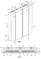
- Figure 1 shows a perspective view of a heating element 1 for Structure of an underfloor heating system consisting of a plate and rectangular, massive cuboid 1, which is preferably made of ceramic material consists. From the one main surface facing the room 21 starting from the heating element 1 has the same along each other, preferably parallel and at equidistant distances from each other Grooves 2, 3, 4, which are open longitudinally to the main surface 22.
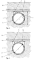
- Grooves 2, 3, 4 are lines 14, 15, 16 inserted in a form-fitting, airtight manner, the depth s of the grooves slightly greater than or equal to at most Diameter d of the line is. The lines therefore run directly adjacent or only a few millimeters below the main surface 21.
- the cross section of the grooves corresponds to that of the lines shaped and usually part circular.
- the inside width of the grooves corresponds to the diameter d of the lines, so that they are positively and airtight in the grooves.
- the lines lie after being pressed into the grooves; what under elastic deformation the lines are made in a form-fitting, airtight manner in the grooves.
- one longitudinal residual joint 17, 24 formed by means of a filling material 18, such as mortar or adhesive or ceramic spatula adhesive, which optionally mixed with clay and / or glass grinding sludge, airtight is grouted so that the main surface 21 is smooth and airtight.
- a filling material 18 such as mortar or adhesive or ceramic spatula adhesive, which optionally mixed with clay and / or glass grinding sludge, airtight is grouted so that the main surface 21 is smooth and airtight.
- the cuboid 1 also has the longitudinal grooves 2, 3, 4 opposite it Main surface 22 recesses 7, 8, which continuously in the two end faces 25, 26 of the cuboid 1 and which by two longitudinal edge webs 9, 10 and a central web 11 are limited, which extend in the same direction as the longitudinal grooves.
- the Recesses 7, 8 can have a dovetail cross section exhibit.
- the edge webs 9, 10 and the central web 11 serve to support the Heating element on the support floor 28
- the main surface 21 of the cuboid 1 is then tiles 20 or Tiles or wood or other flooring applied.
- the longitudinal channels can also be used to guide warm air or for air insulation serve.
- the heating element in its two side faces opposite longitudinal surfaces 39, 40 each have a longitudinal groove 5 and a tongue 6 for tongue and groove installation of two adjacent heating elements.
- Figure 5 shows a half end portion 29 of a heating element, which Heating elements 1 is docked with curved longitudinal grooves 30, 31, 32 for the meandering return of the lines to neighboring ones Heating elements.
- Figure 6 shows a corner heating element 33 with two perpendicular to each other shaped longitudinal legs 35, 35, in which how described above, from the main surfaces facing the room starting from, longitudinal grooves and, in the facing the wall Main surfaces starting, recesses are located. The legs can are also at an angle to each other.
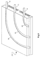
- Figures 7 and 8 show two Wall heating elements 36, 37, in which in the wall side The main surface is only a continuous recess without a central web is arranged. In this configuration, preference is given within the main surface on the room side between four to six longitudinal grooves arranged.
- These heating elements 33, 36, 37 can also be on the wall be screwed.
- Figure 8 is a wall heating element shown, the plate body 38 is convexly curved
- a heating element preferably has a length of approximately 50 to 100 cm, a width of 25 - 50 cm and a thickness of 5 to 7 cm, the The depth s of the grooves is between 12 and 22 mm.
- a heating element for the construction of a floor and / or wall and / or ceiling heating consisting of a plate-shaped cuboid made of ceramic, stoneware, earthenware or clay procedurally the form - plastic, pressable raw material clay for Ceramics, stoneware or stoneware from a press using a template endlessly extruded, the free cross section of the heating element having; the strand is continuously cut into pieces the length of the future Heating element cut, dried and then fired be, preferably at temperatures around 980 degrees Celsius Achieving a dense piece of broken glass. If a pourable raw material is used, namely concrete, hard plastic, glass or reinforced Fibers, so the material is in a positive shape according to the Cast shape of the cuboid.
- Figure 9 shows a further heating element 41, in a perspective view seen from the bottom, this heating element 41st is constructed similarly to the heating element 1 of FIG. 1.
- this heating element 41st is constructed similarly to the heating element 1 of FIG. 1.
- the heating element 41 On the lower main surface, the heating element 41 has lengthways running edge webs 42, 43, between which there is a central web 44 is located, so that between these edge webs 42, 43 and center web 44 longitudinal channels 45, 46 running along the lines 14, 15, 16 which preferably have a trapezoidal cross section in principle, as can be seen in FIG. 9. At the bottom of the longitudinal channels 45, 46 run longitudinal grooves 47, which compensate for expansion of the heating element 41 serve.
- the edge webs 42, 43 and the central web 44 form Load stamp with which the heating elements 41 rest on their wing.
- the transverse channels 48, 49 and 50 penetrate in their Continuing the longitudinal channels 45, 46 so that the transverse channels into the Longitudinal surfaces of the heating element 41 open out.
- the heating element 41 through the longitudinal channels 45, 46 both longitudinally, as also ventilated transversely through the transverse channels 48, 49, 50.
- this longitudinal and transverse ventilation has the advantage that it creates a excellent insulation of the heating element 41 from the Bottom or wing is reached. Trials have shown that with such a heating element the new heating cost regulation in their prescribed new values to be observed are far exceeded.
- this heating element 41 also has one longitudinal side wall 51 and preferably in a transverse side wall a longitudinal groove 53 on, as well as on the opposite long side wall and a spring is preferably formed in one of the transverse side walls 52.
- the heating element is particularly suitable for building a floor and / or wall and / or ceiling heating commercially applicable as well it for the construction and indirect heating of tiled stoves, tepidariums and painting systems due to the high proportion of radiant heat is commercially applicable.
Landscapes
- Engineering & Computer Science (AREA)
- Physics & Mathematics (AREA)
- Thermal Sciences (AREA)
- Chemical & Material Sciences (AREA)
- Combustion & Propulsion (AREA)
- Mechanical Engineering (AREA)
- General Engineering & Computer Science (AREA)
- Floor Finish (AREA)
- Central Heating Systems (AREA)
- Building Environments (AREA)
Abstract
Description
- Figur 1
- eine perspektivische Darstellung eines Heizungselementes mit in die Längsnuten eingelegten Leitungen für-das Heizmedium sowie mit unterseitiger Isolierung
- Figur 2
- einen Querschnitt durch das Heizungselement der Figur 1
- Figur 3
- einen vergrößerten Querschnitt durch ein Heizungselement im Bereich einer Längsnut für eine elastische Leitung
- Figur 4
- einen vergrößerten Querschnitt durch ein Heizungselement im Bereich einer Längsnut für eine starre Leitung
- Figur 5
- ein halbes Endteil für die mäanderförmige Rückführung der Leitungen in benachbarten Heizungselementen
- Figur 6
- ein Wandeck-Heizungselement in perspektivischer Darstellung
- Figur 7
- ein flächiges Wandelement
- Figur 8
- ein gekrümmtes, flächiges Wandelement und
- Figur 9
- eine weitere Ausführungsform eines Heizungselementes in perspektivischer Darstellung mit unterseitigen Längsnuten und Quernuten zur Belüftung.
Claims (24)
- Fußboden- und/oder Wand- und/oder Deckenheizung, bestehend aus einzelnen Heizungselementen in Form von plattenförmigen Quadern (1,29), die parallel zueinander verlaufende Aussparungen (2,3,4) aufweisen, die in sich gegenüberliegende Stirnflächen (25,26) des Quaders (1) münden und die Enden der Aussparungen (2,3,4) zweier benachbarter Quader (1), die mit ihren Stirnflächen (25,26) aneinanderstoßen, sich decken, wobei in die Aussparungen (2,3,4) wenigstens eine ein Heiz- oder Kühlmedium führende Leitung (14,15,16) verlegt und über eine Mehrzahl derartiger Heizungselemente geführt ist, dadurch gekennzeichnet,
dass die Aussparungen von einer der Hauptoberflächen (21,22) des Quaders (1) ausgehende, zu dieser Hauptoberfläche (21,22) hin offene Längsnuten (2,3,4) sind, deren Tiefe (s) geringfügig größer bis höchstens gleich dem Durchmesser (d) der Leitung (14,15,16) ist, die in den Längsnuten (2,3,4) längs formschlüssig-luftdicht angeordnet ist, und somit die Leitungen (14,15,16) der Hauptoberfläche (21,22) benachbart sind, wobei die zwischen Oberseite der Leitungen (14,15,16) innerhalb der Längsnuten (2,3,4) und der Hauptoberfläche (21,22) des Quaders (1) gebildete Restfuge (17,24) mittels eines Füllmaterials luftdicht (18) verfugt ist. - Fußboden- und/oder Wand- und/oder Deckenheizung nach Anspruch 1,
dadurch gekennzeichnet, dass der Quader (1) auch in seiner den Längsnuten (2,3,4) gegenüberliegenden Hauptoberfläche (21,22) Aussparungen (7,8), vorzugsweise in Form von Längskanälen, aufweist, in denen wärmeisolierende Isolierkörper (12,13) angeordnet sind oder die Aussparungen bzw. Längskanäle zur Leitung von Warm- oder Kaltluft oder zur Luftisolation dienen. - Fußboden- und/oder Wand- und/oder Deckenheizung nach Anspruch 2,
dadurch gekennzeichnet, dass die luftführenden Aussparungen (45,46), vorzugsweise in Form von Längskanälen (45,46), von luftführenden Querkanälen (48,49,50) durchsetzt sind. - Fußboden- und/oder Wand- und/oder Deckenheizung nach Anspruch 1 oder 2, dadurch gekennzeichnet, dass die Heizungselementen in Form von plattenförmigen Quadern (1) aus Keramik, Steinzeug, Steingut, Ton, Beton, Hartkunststoffen, Glas, armierten Faserstoffen oder Holz bestehen.
- Fußboden- und/oder Wand- und/oder Deckenheizung nach einem der Ansprüche 1 oder 2 oder 3,
dadurch gekennzeichnet, dass auf der die Längsnuten (2,3,4) und die Leitungen (14,15,16) aufweisenden Hauptoberfläche (21) des Quaders (1) Fliesen (20) oder Kacheln oder Holz oder ein sonstiger Bodenbelag aufgebracht ist. - Fußboden- und/oder Wand- und/oder Deckenheizung nach einem der vorherigen Ansprüche, dadurch gekennzeichnet,
dass die Leitungen entweder flexible Schläuche (14,15,16) oder metallische Rohre (23) für das Heizmedium Wasser oder elektrische Leitungen für das Heizmedium elektrische Energie jeweils mit kreisrundem Querschnitt sind. - Fußboden- und/oder Wand- und/oder Deckenheizung nach einem der vorherigen Ansprüche, dadurch gekennzeichnet,
dass das Füllmaterial für die Restfugen (17,24) des Quaders (1) ein Mörtel oder Kleber oder keramischer Spachtelkleber ist, welcher gegebenenfalls mit Ton und/oder Glasschleifschlamm vermischt ist. - Heizungselement zum Aufbau einer Fußboden- und/oder Wand- und/oder Deckenheizung, bestehend aus einem plattenförmigen Quader (1,29), der parallel zueinander verlaufende Aussparungen (2,3,4) aufweist, die in sich gegenüberliegende Stirnflächen (25,26) des Quaders (1) münden und die Enden der Aussparungen (2,3,4) zweier benachbarter Quader (1), die mit ihren Stirnflächen (25,26) aneinanderstoßen, sich decken, wobei in die Aussparungen (2,3,4) wenigstens eine ein Heizmedium führende Leitung (14,15,16) verlegbar ist, dadurch gekennzeichnet,
dass die Aussparungen von einer der Hauptoberflächen (21,22) des Quaders (1) ausgehende, zu dieser Hauptoberfläche (21,22) hin offene Längsnuten (2,3,4) sind, deren Tiefe (s) geringfügig größer bis höchstens gleich dem Durchmesser (d) der in den Längsnuten (2,3,4) zu verlegenden Leitung (14,15,16) ist, - Heizungselement nach Anspruch 8, dadurch gekennzeichnet,
dass der Quader (1) auch in seiner den Längsnuten (2,3,4) gegenüberliegenden Hauptoberfläche (21,22) wenigstens eine flächige Aussparung (7,8,45,46), vorzugsweise in Form eines Längskanals, aufweist, die wenigstens von zwei längs verlaufenden Randstegen begrenzt ist und in der ein wärmeisolierender Isolierkörper (12,13) angeordnet ist. - Heizungselement nach Anspruch 9, dadurch gekennzeichnet,
dass der Quader (1) zur Verwendung als Bodenelement zwei oder mehr Aussparungen (7,8,45,46), vorzugsweise in Form von Längskanälen, aufweist, die durch wenigstens einen Mittelsteg (11) unterteilt und an den Seitenkanten von je einem längs verlaufenden Randsteg (9,10) begrenzt sind, wobei in der Projektion der oberen, die Längsnuten (2,3,4) aufweisenden Hauptoberfläche (21) auf die untere, die Aussparungen (7,8) aufweisende Hauptoberfläche (22) jeweils oberhalb eines Mittelsteges (11) eine Längsnut (2,3,4) verläuft. - Heizungselement nach Anspruch 9 oder 10, dadurch gekennzeichnet,
dass die luftführenden Aussparungen (45,46), vorzugsweise in Form von Längskanälen (45,46) des Heizungselements (41) von luftführenden Querkanälen (48,49,50) durchsetzt sind, welche quer verlaufend in den Randstegen (9,10) und dem/den Mittelsteg/en (11) angeordnet sind. - Heizungselement nach einem der Ansprüche 8 bis 11,
dadurch gekennzeichnet, dass zur Erzielung eines luftdichten Formschlusses der flexiblen Schläuche (14,15,16) innerhalb der Längsnuten (2,3,4) die lichte Weite derselben längs der Einmündung in die Hauptoberfläche kleiner ist als der Radius (r) des ansonsten kreisrunden Querschnitts der Längsnut (2,3,4). - Heizungselement nach einem der vorherigen Ansprüche 8 bis 12,
dadurch gekennzeichnet, dass die Aussparungen (7,8,45,46) einen schwalbenschwanzförmigen oder trapezförmigen Querschnitt aufweisen. - Heizungselement nach einem der vorherigen Ansprüche 8 bis 13,
dadurch gekennzeichnet, dass dasselbe auf seinen zwei seitlichen, sich gegenüberliegenden Längsflächen (39,40) je eine Längsnut (5) und eine Feder (6) zur Nut-und-Federverlegung zweier benachbarter Heizungselemente (1) aufweist. - Heizungselement nach einem der vorherigen Ansprüche 8 bis 14,
dadurch gekennzeichnet, dass bei der Verwendung desselben als Wandelement dieses nur eine einzige, von je einem längs verlaufenden Randsteg begrenzte Aussparung aufweist, und auf der gegenüberliegenden Hauptoberfläche zwischen vier bis sechs Längsnuten angeordnet sind. - Heizungselement nach einem der vorherigen Ansprüche 8 bis 15 zur Verwendung als Wandelement, dadurch gekennzeichnet, dass dasselbe als rechtwinkliges oder schiefwinkliges Eckelement (33) mit zwei Längsschenkeln (34,35) ausgebildet ist.
- Heizungselement nach einem der vorherigen Ansprüche 7 bis 16, zur Verwendung als Wandelement (37), dadurch gekennzeichnet,
dass dasselbe gekrümmt ausgestaltet ist. - Heizungselement nach einem der vorherigen Ansprüche 8 bis 17,
dadurch gekennzeichnet, dass dasselbe ungefähr eine Länge zwischen 50 bis 100 cm, eine Breite von 25 - 50 cm und eine Dicke von 5 bis 7 cm aufweist, wobei die Tiefe der Nuten zwischen 12 bis 22 mm beträgt. - Heizungselement nach einem der vorherigen Ansprüche 8 bis 17,
dadurch gekennzeichnet, dass es aus Keramik, Steinzeug, Steingut, Ton, Beton, Hartkunststoffen, Glas, armierten Faserstoffen oder Holz besteht. - Verfahren zur Herstellung eines Heizungselementes zum Aufbau einer Fußboden- und/oder Wand- und/oder Deckenheizung, bestehend aus einem plattenförmigen Quader (1) aus Keramik, Steinzeug, Steingut oder Ton gemäß der Ausgestaltung nach Anspruch 8, dadurch gekennzeichnet,
dass das formplastische, preßbare Ausgangsmaterial Ton für Keramik, Steinzeug, oder Steingut aus einer Presse mittels einer Schablone endlos stranggepreßt wird, die den freien Querschnitt des Heizungselementes aufweist und der Strang fortlaufend in Stücke der Länge des künftigen Heizungselementes geschnitten wird, die getrocknet und anschließend gebrannt werden, vorzugsweise bei Temperaturen um die 980 Grad Celsius zur Erzielung eines dichten Scherben. - Verfahren zur Herstellung eines Heizungselementes gemäß der Ausgestaltung nach Anspruch 8 zum Aufbau einer Fußboden- und/oder Wand- und/oder Deckenheizung, dadurch gekenhzeichnet, dass ein gießfähiges Ausgangsmaterial verwendet wird, nämlich Beton, Hartkunststoff, Glas oder armierte Faserstoffe und das Material in eine positive Form entsprechend der Form des Quaders gegossen wird.
- Verwendung eines Heizungselementes der Ausgestaltung gemäß Anspruch 8 zum Aufbau einer Fußboden- und/oder Wand- und/oder Deckenheizung gemäß Anspruch 1.
- Fußboden- und/oder Wand- und/oder Deckenheizung nach einem der Ansprüche 1 bis 7, dadurch gekennzeichnet, dass der Abstand der Leitung (14, 15, 16) zur Hauptoberfläche (21) und/oder die Dicke der Restfugen (17, 24) zwischen der Leitung (14, 15, 16) und der Wandung der Längsnuten (2, 3, 4) weniger als 20 mm, vorzugsweise weniger als 15 mm, weniger als 10 mm oder insbesondere weniger als 5 mm beträgt.
- Heizungselement nach einem der Ansprüche 8 bis 19, dadurch gekennzeichnet, dass der Abstand der Leitung (14, 15, 16) zur Hauptoberfläche (21) und/oder die Dicke der Restfugen (17, 24) zwischen der Leitung (14, 15, 16) und der Wandung der Längsnuten (2, 3, 4) weniger als 20 mm, vorzugsweise weniger als 15 mm, weniger als 10 mm oder insbesondere weniger als 5 mm beträgt.
Applications Claiming Priority (4)
| Application Number | Priority Date | Filing Date | Title |
|---|---|---|---|
| DE19929338 | 1999-06-26 | ||
| DE19929338 | 1999-06-26 | ||
| DE19931759 | 1999-07-08 | ||
| DE19931759A DE19931759A1 (de) | 1999-06-26 | 1999-07-08 | Fußboden- und/oder Wand- und/oder Deckenheizung aus Heizungselementen sowie derartige Heizungselemente und Verfahren zur Herstellung derselben |
Publications (3)
| Publication Number | Publication Date |
|---|---|
| EP1063478A2 true EP1063478A2 (de) | 2000-12-27 |
| EP1063478A3 EP1063478A3 (de) | 2001-01-31 |
| EP1063478B1 EP1063478B1 (de) | 2003-10-22 |
Family
ID=26053938
Family Applications (1)
| Application Number | Title | Priority Date | Filing Date |
|---|---|---|---|
| EP99115893A Expired - Lifetime EP1063478B1 (de) | 1999-06-26 | 1999-08-12 | Fussboden- und/oder Wand- und/oder Deckenheizung aus Heizungselementen sowie derartige Heizungselemente |
Country Status (2)
| Country | Link |
|---|---|
| EP (1) | EP1063478B1 (de) |
| AT (1) | ATE252712T1 (de) |
Cited By (20)
| Publication number | Priority date | Publication date | Assignee | Title |
|---|---|---|---|---|
| EP1327828A1 (de) * | 2002-01-11 | 2003-07-16 | Baustoffe Guth GmbH & Co.KG | Wandheizung oder Fussbodenheizung mit Heizleitungen zwischen Schamottesteinen |
| EP1353129A1 (de) * | 2002-04-10 | 2003-10-15 | Polypipe Building Products Ltd. | Fussbodenheizung auf bestehendem Boden |
| EP1419348A4 (de) * | 2000-08-15 | 2005-01-05 | Michael Fitzemeyer | Montageplatte zur befestigung eines strahlungswärmesystemrohrs |
| CN100371553C (zh) * | 2005-06-20 | 2008-02-27 | 南京林业大学 | 复合地热地板 |
| NL1033859C2 (nl) * | 2007-05-16 | 2008-11-18 | Infill Systems Bv | Systeem voor het aanleggen van leidingen in een vloer en daarbij toe te passen tegel. |
| ES2324590A1 (es) * | 2009-02-03 | 2009-08-10 | Rafael Garcia Quesada | Bloque termoarcilla preparado para ubicacion de instalaciones sin aperturas de rozas. |
| ES2324811A1 (es) * | 2009-02-03 | 2009-08-14 | Rafael Garcia Quesada | Ladrillo ceramico extrusionado preparado para ubicacion de instalaciones sin aperturas de rozas. |
| DE102008055978A1 (de) | 2008-11-05 | 2010-05-06 | Brecht, Wido E. | Platten-Unterbau zum flächigen Verlegen von Rohrleitungen für Heiz- Kühl- oder Absorberzwecke, zum Beispiel für Fußboden- oder Wandheizungen sowie Verfahren zur Herstellung einer solchen Heizung |
| US9416979B2 (en) | 2009-08-28 | 2016-08-16 | Progress Profiles Spa | Method and apparatus for positioning heating elements |
| US9625163B2 (en) | 2014-08-18 | 2017-04-18 | Progress Profiles Spa | Method and apparatus for positioning heating elements |
| US9719265B2 (en) | 2015-03-17 | 2017-08-01 | Progress Profiles Spa | Floor underlayment for positioning heating elements |
| US9726383B1 (en) | 2016-06-17 | 2017-08-08 | Progress Profiles S.P.A. | Support for radiant covering and floor heating elements |
| US9797146B2 (en) | 2012-09-12 | 2017-10-24 | Schluter Systems L.P. | Veneer underlayment |
| US10859274B2 (en) | 2016-04-01 | 2020-12-08 | Progress Profiles S.P.A. | Support for radiant covering and floor heating elements |
| EP3760934A1 (de) | 2019-07-01 | 2021-01-06 | Fundación Tecnalia Research & Innovation | Wärmeableitende struktur und verfahren zur bereitstellung davon |
| USD1036243S1 (en) | 2020-10-09 | 2024-07-23 | Progress Profiles S.P.A. | Floor underlayment |
| US12044016B2 (en) | 2017-03-09 | 2024-07-23 | Schluter Systems L.P. | Uncoupling mat with heating elements |
| USD1036242S1 (en) | 2020-04-22 | 2024-07-23 | Progress Profiles S.P.A. | Floor underlayment |
| USD1036979S1 (en) | 2020-04-06 | 2024-07-30 | Progress Profiles S.P.A. | Floor underlayment |
| USD1101979S1 (en) | 2023-02-07 | 2025-11-11 | Progress Profiles S.P.A. | Floor underlayment |
Families Citing this family (4)
| Publication number | Priority date | Publication date | Assignee | Title |
|---|---|---|---|---|
| DE102004023920B4 (de) * | 2004-05-12 | 2014-05-15 | Kamal Mostafa | Mosaikbelag |
| USD813421S1 (en) | 2009-08-28 | 2018-03-20 | Progress Profiles Spa | Floor underlayment |
| US10215423B2 (en) | 2014-08-18 | 2019-02-26 | Progress Profiles S.P.A. | Method and apparatus for positioning heating elements |
| KR101636627B1 (ko) * | 2014-12-31 | 2016-07-07 | 이신춘 | 조립식 경량 및 고강도 황토 온돌패널 |
Citations (1)
| Publication number | Priority date | Publication date | Assignee | Title |
|---|---|---|---|---|
| DE4126430A1 (de) | 1990-08-07 | 1992-03-05 | Michael Brenner | Verfahren zum erstellen eines allseits umschlossenen raumes, der eine homogene strahlungsklimatisierung aufweist, insbesondere tepidarium oder lackierkabine, verwendung eines ziegels zur herstellung des raumes und dergestalt erstellter, allseits umschlossener raum |
Family Cites Families (7)
| Publication number | Priority date | Publication date | Assignee | Title |
|---|---|---|---|---|
| DE2838603A1 (de) * | 1978-09-05 | 1980-03-06 | Hartmann Georg Elektr | Heizkoerper |
| DE3208278A1 (de) * | 1982-03-08 | 1983-09-15 | Gerhard 5952 Attendorn Rosenberg | Schablonenplatte zum verlegen von fussbodenheizungsrohren |
| DE3215902A1 (de) * | 1982-04-29 | 1983-11-03 | Wirsbo Pex, Zweigniederlassung der Platzer Schwedenbau GmbH, 6056 Heusenstamm | Heizflaeche fuer fussbodenheizung |
| DE3367790D1 (en) * | 1982-11-20 | 1987-01-08 | Hartmut Groll | Tile, modular tile |
| DE9314110U1 (de) * | 1993-09-17 | 1994-10-27 | Sandler Energietechnik GmbH & Co. KG, 87600 Kaufbeuren | Plattenförmiger Wärmetauscher |
| DE19605142C1 (de) * | 1996-02-13 | 1999-10-14 | Schlueter Systems Gmbh | Fußbodenverbundkörper |
| DE29801344U1 (de) * | 1998-01-28 | 1998-04-30 | emcal Wärmesysteme GmbH, 48282 Emsdetten | Wärmetauscherdecke mit Wärmeleitelementen |
-
1999
- 1999-08-12 EP EP99115893A patent/EP1063478B1/de not_active Expired - Lifetime
- 1999-08-12 AT AT99115893T patent/ATE252712T1/de not_active IP Right Cessation
Patent Citations (1)
| Publication number | Priority date | Publication date | Assignee | Title |
|---|---|---|---|---|
| DE4126430A1 (de) | 1990-08-07 | 1992-03-05 | Michael Brenner | Verfahren zum erstellen eines allseits umschlossenen raumes, der eine homogene strahlungsklimatisierung aufweist, insbesondere tepidarium oder lackierkabine, verwendung eines ziegels zur herstellung des raumes und dergestalt erstellter, allseits umschlossener raum |
Cited By (35)
| Publication number | Priority date | Publication date | Assignee | Title |
|---|---|---|---|---|
| EP1419348A4 (de) * | 2000-08-15 | 2005-01-05 | Michael Fitzemeyer | Montageplatte zur befestigung eines strahlungswärmesystemrohrs |
| EP1327828A1 (de) * | 2002-01-11 | 2003-07-16 | Baustoffe Guth GmbH & Co.KG | Wandheizung oder Fussbodenheizung mit Heizleitungen zwischen Schamottesteinen |
| EP1353129A1 (de) * | 2002-04-10 | 2003-10-15 | Polypipe Building Products Ltd. | Fussbodenheizung auf bestehendem Boden |
| CN100371553C (zh) * | 2005-06-20 | 2008-02-27 | 南京林业大学 | 复合地热地板 |
| NL1033859C2 (nl) * | 2007-05-16 | 2008-11-18 | Infill Systems Bv | Systeem voor het aanleggen van leidingen in een vloer en daarbij toe te passen tegel. |
| WO2008140303A1 (en) * | 2007-05-16 | 2008-11-20 | Infill Systems B.V. | System for arranging lines in a floor and tile for use therein |
| DE102008055978A1 (de) | 2008-11-05 | 2010-05-06 | Brecht, Wido E. | Platten-Unterbau zum flächigen Verlegen von Rohrleitungen für Heiz- Kühl- oder Absorberzwecke, zum Beispiel für Fußboden- oder Wandheizungen sowie Verfahren zur Herstellung einer solchen Heizung |
| ES2324811B1 (es) * | 2009-02-03 | 2010-03-12 | Rafael Garcia Quesada | Ladrillo ceramico extrusionado preparado para ubicacion de instalaciones sin apertura de rozas. |
| ES2324590B1 (es) * | 2009-02-03 | 2010-03-12 | Rafael Garcia Quesada | Bloque termoarcilla preparado para ubicacion de instalaciones sin aperturas de rozas. |
| ES2324811A1 (es) * | 2009-02-03 | 2009-08-14 | Rafael Garcia Quesada | Ladrillo ceramico extrusionado preparado para ubicacion de instalaciones sin aperturas de rozas. |
| ES2324590A1 (es) * | 2009-02-03 | 2009-08-10 | Rafael Garcia Quesada | Bloque termoarcilla preparado para ubicacion de instalaciones sin aperturas de rozas. |
| US9416979B2 (en) | 2009-08-28 | 2016-08-16 | Progress Profiles Spa | Method and apparatus for positioning heating elements |
| US9518746B2 (en) | 2009-08-28 | 2016-12-13 | Progress Profiles Spa | Method and apparatus for positioning heating elements |
| US11041638B2 (en) | 2009-08-28 | 2021-06-22 | Progress Profiles Spa | Method and apparatus for positioning heating elements |
| US9797146B2 (en) | 2012-09-12 | 2017-10-24 | Schluter Systems L.P. | Veneer underlayment |
| US10822812B2 (en) | 2012-09-12 | 2020-11-03 | Schluter Systems L.P. | Veneer underlayment |
| US10392814B2 (en) | 2012-09-12 | 2019-08-27 | Schluter Systems L. P. | Veneer underlayment |
| US9777931B2 (en) | 2014-08-18 | 2017-10-03 | Progress Profiles Spa | Method and apparatus for positioning heating elements |
| US9625163B2 (en) | 2014-08-18 | 2017-04-18 | Progress Profiles Spa | Method and apparatus for positioning heating elements |
| US10408469B2 (en) | 2014-08-18 | 2019-09-10 | Progress Profiles Spa | Method and apparatus for positioning heating elements |
| US12044417B2 (en) | 2014-08-18 | 2024-07-23 | Progress Profiles Spa | Method and apparatus for positioning heating elements |
| US10712020B2 (en) | 2014-08-18 | 2020-07-14 | Progress Profiles Spa | Method and apparatus for positioning heating elements |
| US10739016B2 (en) | 2014-08-18 | 2020-08-11 | Progress Profiles Spa | Method and apparatus for positioning heating elements |
| US9719265B2 (en) | 2015-03-17 | 2017-08-01 | Progress Profiles Spa | Floor underlayment for positioning heating elements |
| US10859274B2 (en) | 2016-04-01 | 2020-12-08 | Progress Profiles S.P.A. | Support for radiant covering and floor heating elements |
| US10502434B2 (en) | 2016-04-01 | 2019-12-10 | Progress Profiles S.P.A. | Support for radiant covering and floor heating elements |
| US12560339B2 (en) | 2016-04-01 | 2026-02-24 | Progress Profiles S.P.A. | Support for radiant covering and floor heating elements |
| US9726383B1 (en) | 2016-06-17 | 2017-08-08 | Progress Profiles S.P.A. | Support for radiant covering and floor heating elements |
| US12044016B2 (en) | 2017-03-09 | 2024-07-23 | Schluter Systems L.P. | Uncoupling mat with heating elements |
| US12297651B2 (en) | 2017-03-09 | 2025-05-13 | Schluter Systems L.P. | Uncoupling mat with heating elements |
| EP3760934A1 (de) | 2019-07-01 | 2021-01-06 | Fundación Tecnalia Research & Innovation | Wärmeableitende struktur und verfahren zur bereitstellung davon |
| USD1036979S1 (en) | 2020-04-06 | 2024-07-30 | Progress Profiles S.P.A. | Floor underlayment |
| USD1036242S1 (en) | 2020-04-22 | 2024-07-23 | Progress Profiles S.P.A. | Floor underlayment |
| USD1036243S1 (en) | 2020-10-09 | 2024-07-23 | Progress Profiles S.P.A. | Floor underlayment |
| USD1101979S1 (en) | 2023-02-07 | 2025-11-11 | Progress Profiles S.P.A. | Floor underlayment |
Also Published As
| Publication number | Publication date |
|---|---|
| EP1063478A3 (de) | 2001-01-31 |
| EP1063478B1 (de) | 2003-10-22 |
| ATE252712T1 (de) | 2003-11-15 |
Similar Documents
| Publication | Publication Date | Title |
|---|---|---|
| EP1063478B1 (de) | Fussboden- und/oder Wand- und/oder Deckenheizung aus Heizungselementen sowie derartige Heizungselemente | |
| WO1997030247A1 (de) | Fussbodenverbundkörper | |
| DE3242942A1 (de) | Fliese | |
| DE202006015397U1 (de) | Mehrschichtiges Aufbausystem für Bodenbeläge bei Fußbodenheizungen | |
| DE19801123B4 (de) | Fundamentaufbau sowie Sockelelement für die Verwendung darin | |
| DE29618705U1 (de) | Bausystem zur Erstellung von Gebäuden | |
| DE4021081A1 (de) | Hohles, plattenfoermiges bauteil | |
| EP0111763B1 (de) | Fliese, Fliesenbaustein | |
| DE19931759A1 (de) | Fußboden- und/oder Wand- und/oder Deckenheizung aus Heizungselementen sowie derartige Heizungselemente und Verfahren zur Herstellung derselben | |
| EP1070796A1 (de) | Hohlblocktonziegel | |
| EP0111235A2 (de) | Vorgefertigtes Verbundelement zur Aussenisolierung von Gebäudewänden | |
| DE2809086C2 (de) | Keramikplatte zur Klimatisierung von Räumen | |
| DE29911861U1 (de) | Heizungselement sowie Fußboden- und/oder Wand- und/oder Deckenheizung aus derartigen Heizungselementen | |
| DE8800710U1 (de) | Fußbodenelement | |
| DE19950356C2 (de) | Mehrschichtige Bauplatte, sowie Verfahren zu ihrer Herstellung | |
| WO2019180605A1 (de) | Bauprodukt | |
| EP1911899A2 (de) | Bausystem | |
| DE2755323A1 (de) | Beheizbarer fussboden | |
| AT369838B (de) | Abdeckung von gebaeudeteilen, insb. fussboeden oder raumwaenden | |
| DE926571C (de) | Strahlungsheizungsanlage mit in die Raumbegrenzungsbauteile eingebetteten Heizroehren | |
| DE2640539B2 (de) | Beheizbarer Unterboden | |
| CH721096A2 (de) | Unterlagsboden, insbesondere mit einer Bodenheizung | |
| EP1835086A2 (de) | Mauerstein mit zweischaligem Aufbau | |
| DE29904167U1 (de) | Plattenartiger Formstein für Heizanlagen | |
| DE3517976A1 (de) | Doppelboden |
Legal Events
| Date | Code | Title | Description |
|---|---|---|---|
| PUAI | Public reference made under article 153(3) epc to a published international application that has entered the european phase |
Free format text: ORIGINAL CODE: 0009012 |
|
| PUAL | Search report despatched |
Free format text: ORIGINAL CODE: 0009013 |
|
| AK | Designated contracting states |
Kind code of ref document: A2 Designated state(s): AT BE CH CY DE DK ES FI FR GB GR IE IT LI LU MC NL PT SE |
|
| AX | Request for extension of the european patent |
Free format text: AL;LT;LV;MK;RO;SI |
|
| AK | Designated contracting states |
Kind code of ref document: A3 Designated state(s): AT BE CH CY DE DK ES FI FR GB GR IE IT LI LU MC NL PT SE |
|
| AX | Request for extension of the european patent |
Free format text: AL;LT;LV;MK;RO;SI |
|
| AKX | Designation fees paid | ||
| 17P | Request for examination filed |
Effective date: 20011015 |
|
| RBV | Designated contracting states (corrected) |
Designated state(s): AT BE CH CY DE DK ES FI FR GB GR IE IT LI LU MC NL PT SE |
|
| RAP1 | Party data changed (applicant data changed or rights of an application transferred) |
Owner name: KAUFMANN KERAMIK GMBH |
|
| 17Q | First examination report despatched |
Effective date: 20020402 |
|
| RTI1 | Title (correction) |
Free format text: UNDERFLOOR AND/OR WALL AND/OR CEILING HEATING WITH HEATING ELEMENTS, AND SUCH HEATING ELEMENTS |
|
| GRAH | Despatch of communication of intention to grant a patent |
Free format text: ORIGINAL CODE: EPIDOS IGRA |
|
| GRAS | Grant fee paid |
Free format text: ORIGINAL CODE: EPIDOSNIGR3 |
|
| GRAA | (expected) grant |
Free format text: ORIGINAL CODE: 0009210 |
|
| AK | Designated contracting states |
Kind code of ref document: B1 Designated state(s): AT BE CH CY DE DK ES FI FR GB GR IE IT LI LU MC NL PT SE |
|
| PG25 | Lapsed in a contracting state [announced via postgrant information from national office to epo] |
Ref country code: IE Free format text: LAPSE BECAUSE OF FAILURE TO SUBMIT A TRANSLATION OF THE DESCRIPTION OR TO PAY THE FEE WITHIN THE PRESCRIBED TIME-LIMIT Effective date: 20031022 Ref country code: FI Free format text: LAPSE BECAUSE OF FAILURE TO SUBMIT A TRANSLATION OF THE DESCRIPTION OR TO PAY THE FEE WITHIN THE PRESCRIBED TIME-LIMIT Effective date: 20031022 Ref country code: CY Free format text: LAPSE BECAUSE OF FAILURE TO SUBMIT A TRANSLATION OF THE DESCRIPTION OR TO PAY THE FEE WITHIN THE PRESCRIBED TIME-LIMIT Effective date: 20031022 |
|
| REG | Reference to a national code |
Ref country code: GB Ref legal event code: FG4D Free format text: NOT ENGLISH |
|
| REG | Reference to a national code |
Ref country code: CH Ref legal event code: EP |
|
| REG | Reference to a national code |
Ref country code: IE Ref legal event code: FG4D Free format text: GERMAN |
|
| REF | Corresponds to: |
Ref document number: 59907451 Country of ref document: DE Date of ref document: 20031127 Kind code of ref document: P |
|
| PG25 | Lapsed in a contracting state [announced via postgrant information from national office to epo] |
Ref country code: SE Free format text: LAPSE BECAUSE OF FAILURE TO SUBMIT A TRANSLATION OF THE DESCRIPTION OR TO PAY THE FEE WITHIN THE PRESCRIBED TIME-LIMIT Effective date: 20040122 Ref country code: GR Free format text: LAPSE BECAUSE OF FAILURE TO SUBMIT A TRANSLATION OF THE DESCRIPTION OR TO PAY THE FEE WITHIN THE PRESCRIBED TIME-LIMIT Effective date: 20040122 Ref country code: DK Free format text: LAPSE BECAUSE OF FAILURE TO SUBMIT A TRANSLATION OF THE DESCRIPTION OR TO PAY THE FEE WITHIN THE PRESCRIBED TIME-LIMIT Effective date: 20040122 |
|
| PG25 | Lapsed in a contracting state [announced via postgrant information from national office to epo] |
Ref country code: ES Free format text: LAPSE BECAUSE OF FAILURE TO SUBMIT A TRANSLATION OF THE DESCRIPTION OR TO PAY THE FEE WITHIN THE PRESCRIBED TIME-LIMIT Effective date: 20040202 |
|
| GBT | Gb: translation of ep patent filed (gb section 77(6)(a)/1977) |
Effective date: 20040113 |
|
| REG | Reference to a national code |
Ref country code: IE Ref legal event code: FD4D |
|
| ET | Fr: translation filed | ||
| PG25 | Lapsed in a contracting state [announced via postgrant information from national office to epo] |
Ref country code: LU Free format text: LAPSE BECAUSE OF NON-PAYMENT OF DUE FEES Effective date: 20040812 |
|
| PLBE | No opposition filed within time limit |
Free format text: ORIGINAL CODE: 0009261 |
|
| STAA | Information on the status of an ep patent application or granted ep patent |
Free format text: STATUS: NO OPPOSITION FILED WITHIN TIME LIMIT |
|
| PG25 | Lapsed in a contracting state [announced via postgrant information from national office to epo] |
Ref country code: MC Free format text: LAPSE BECAUSE OF NON-PAYMENT OF DUE FEES Effective date: 20040831 |
|
| 26N | No opposition filed |
Effective date: 20040723 |
|
| REG | Reference to a national code |
Ref country code: CH Ref legal event code: PL |
|
| REG | Reference to a national code |
Ref country code: CH Ref legal event code: AEN Free format text: DAS PATENT IST AUFGRUND DES WEITERBEHANDLUNGSANTRAGS VOM 19.04.2005 REAKTIVIERT WORDEN. |
|
| PGFP | Annual fee paid to national office [announced via postgrant information from national office to epo] |
Ref country code: AT Payment date: 20050707 Year of fee payment: 7 |
|
| PGFP | Annual fee paid to national office [announced via postgrant information from national office to epo] |
Ref country code: GB Payment date: 20050802 Year of fee payment: 7 |
|
| PGFP | Annual fee paid to national office [announced via postgrant information from national office to epo] |
Ref country code: NL Payment date: 20050818 Year of fee payment: 7 |
|
| PGFP | Annual fee paid to national office [announced via postgrant information from national office to epo] |
Ref country code: FR Payment date: 20050819 Year of fee payment: 7 |
|
| PGFP | Annual fee paid to national office [announced via postgrant information from national office to epo] |
Ref country code: BE Payment date: 20050823 Year of fee payment: 7 |
|
| PGFP | Annual fee paid to national office [announced via postgrant information from national office to epo] |
Ref country code: CH Payment date: 20051003 Year of fee payment: 7 |
|
| PG25 | Lapsed in a contracting state [announced via postgrant information from national office to epo] |
Ref country code: AT Free format text: LAPSE BECAUSE OF NON-PAYMENT OF DUE FEES Effective date: 20060812 |
|
| PG25 | Lapsed in a contracting state [announced via postgrant information from national office to epo] |
Ref country code: LI Free format text: LAPSE BECAUSE OF NON-PAYMENT OF DUE FEES Effective date: 20060831 Ref country code: CH Free format text: LAPSE BECAUSE OF NON-PAYMENT OF DUE FEES Effective date: 20060831 Ref country code: BE Free format text: LAPSE BECAUSE OF NON-PAYMENT OF DUE FEES Effective date: 20060831 |
|
| PGFP | Annual fee paid to national office [announced via postgrant information from national office to epo] |
Ref country code: IT Payment date: 20060831 Year of fee payment: 8 |
|
| PG25 | Lapsed in a contracting state [announced via postgrant information from national office to epo] |
Ref country code: NL Free format text: LAPSE BECAUSE OF NON-PAYMENT OF DUE FEES Effective date: 20070301 |
|
| REG | Reference to a national code |
Ref country code: CH Ref legal event code: PL |
|
| GBPC | Gb: european patent ceased through non-payment of renewal fee |
Effective date: 20060812 |
|
| NLV4 | Nl: lapsed or anulled due to non-payment of the annual fee |
Effective date: 20070301 |
|
| REG | Reference to a national code |
Ref country code: FR Ref legal event code: ST Effective date: 20070430 |
|
| PG25 | Lapsed in a contracting state [announced via postgrant information from national office to epo] |
Ref country code: GB Free format text: LAPSE BECAUSE OF NON-PAYMENT OF DUE FEES Effective date: 20060812 |
|
| BERE | Be: lapsed |
Owner name: *KAUFMANN KERAMIK G.M.B.H. Effective date: 20060831 |
|
| PG25 | Lapsed in a contracting state [announced via postgrant information from national office to epo] |
Ref country code: PT Free format text: LAPSE BECAUSE OF NON-PAYMENT OF DUE FEES Effective date: 20040322 |
|
| PG25 | Lapsed in a contracting state [announced via postgrant information from national office to epo] |
Ref country code: FR Free format text: LAPSE BECAUSE OF NON-PAYMENT OF DUE FEES Effective date: 20060831 |
|
| PG25 | Lapsed in a contracting state [announced via postgrant information from national office to epo] |
Ref country code: IT Free format text: LAPSE BECAUSE OF NON-PAYMENT OF DUE FEES Effective date: 20070812 |
|
| PGFP | Annual fee paid to national office [announced via postgrant information from national office to epo] |
Ref country code: DE Payment date: 20151023 Year of fee payment: 17 |
|
| REG | Reference to a national code |
Ref country code: DE Ref legal event code: R119 Ref document number: 59907451 Country of ref document: DE |
|
| PG25 | Lapsed in a contracting state [announced via postgrant information from national office to epo] |
Ref country code: DE Free format text: LAPSE BECAUSE OF NON-PAYMENT OF DUE FEES Effective date: 20170301 |