EP1063518A2 - Appareil pour analyser un échantillon gazeux par l'absorption d'infrarouge - Google Patents
Appareil pour analyser un échantillon gazeux par l'absorption d'infrarouge Download PDFInfo
- Publication number
- EP1063518A2 EP1063518A2 EP00111529A EP00111529A EP1063518A2 EP 1063518 A2 EP1063518 A2 EP 1063518A2 EP 00111529 A EP00111529 A EP 00111529A EP 00111529 A EP00111529 A EP 00111529A EP 1063518 A2 EP1063518 A2 EP 1063518A2
- Authority
- EP
- European Patent Office
- Prior art keywords
- receiver
- radiator
- measuring cell
- carrier
- temperature
- Prior art date
- Legal status (The legal status is an assumption and is not a legal conclusion. Google has not performed a legal analysis and makes no representation as to the accuracy of the status listed.)
- Granted
Links
Images

Classifications
-
- G—PHYSICS
- G01—MEASURING; TESTING
- G01N—INVESTIGATING OR ANALYSING MATERIALS BY DETERMINING THEIR CHEMICAL OR PHYSICAL PROPERTIES
- G01N21/00—Investigating or analysing materials by the use of optical means, i.e. using sub-millimetre waves, infrared, visible or ultraviolet light
- G01N21/17—Systems in which incident light is modified in accordance with the properties of the material investigated
- G01N21/25—Colour; Spectral properties, i.e. comparison of effect of material on the light at two or more different wavelengths or wavelength bands
- G01N21/31—Investigating relative effect of material at wavelengths characteristic of specific elements or molecules, e.g. atomic absorption spectrometry
- G01N21/35—Investigating relative effect of material at wavelengths characteristic of specific elements or molecules, e.g. atomic absorption spectrometry using infrared light
- G01N21/3504—Investigating relative effect of material at wavelengths characteristic of specific elements or molecules, e.g. atomic absorption spectrometry using infrared light for analysing gases, e.g. multi-gas analysis
Definitions
- the invention relates to a device for analyzing a gas sample by means of infrared absorption according to the preamble of claim 1.
- NDIR measuring devices non-dispersive infrared
- the determination of an exhaust gas concentration is determined by infrared absorption measurement (IR absorption measurement).
- IR absorption measurement infrared absorption measurement
- a glass cuvette (measuring cell) of a certain length is irradiated, which is generated by a radiator, and the absorption of this emitted light beam is determined within a wave range specific to the gas.
- the wavelength range is determined in a non-dispersive manner, ie by means of an interference filter or certain filter gases.
- a long absorption distance within the measuring cell should be selected for an accurate measurement of low concentrations.
- the absorption measurement only works if the intensity of the light beam is constant during its measurement, whereby the current intensity measurement is compared with a measurement in 0-gas (zero gas) and the ratio is a measure of the exhaust gas concentration (Beer's law) .
- the short-term drift of a receiver receiving the light or an amplifier electronics is minimized by an additional alternating light method, for which purpose the radiation is chopped or the radiator is flashed.
- a medium-term drift of the receiver signals for example due to changes in the temperature of the receiver or the radiator, is minimized either by thermal stabilization of the receiver or by measuring the radiator temperature.
- the receiver signals are usually post-compensated using a non-absorbed wavelength (reference range) of the sample gas by means of a reference receiver, while with chopped emitters, the emitter temperature is readjusted using an additional control circuit.
- An infrared absorption measuring cell of the generic type is in DE 297 22 579 U1 disclosed.
- a measuring section is proposed lengthen in a measuring cell in such a way that additional radiation is caused by radiation reflections built-in mirror surfaces at least four times the measurement beam is realized.
- the emitter and the receiver are on one side of the measuring cell, where both are arranged separately.
- the container in front of the measuring cell is the one from an infrared radiation source (IR radiation source) emitted IR radiation bundled and coupled into the White measuring cell.
- the White measuring cell itself has three concave mirrors with the same radius of curvature on.
- the absorbed IR radiation is then removed from the white measuring cell via the mirrors given to an IR detector.
- the container and the white measuring cell as well as the IR detectors are interconnected and form a compact IR gas analyzer.
- the IR radiation source has an additional photodiode arranged as a detector for recording the amount of light emitted by an emitter element (emitter) works.
- DE 44 20 320 C2 discloses a method for measuring the concentration of a component in a sample gas and an IR gas analyzer to carry out the method.
- the temperature of a light source (radiator) and the emitted light are measured given to detectors (receivers) only when the light source is used for the measurement has reached a suitable and predetermined temperature.
- the spotter is controlled so that it blinks. With this measure, the temperature influence of the light source on the Detectors minimized.
- the invention is based on the idea of a radiator and a receiver on one common, thermally stabilized carrier in close proximity to each other and on one Arrange the side of a measuring cell. Both the receiver temperature as well as the radiator temperature kept constant, which causes the thermal drift of the radiator and the recipient are prevented. This eliminates additional thermal Correction means for the radiator. Since only one temperature stabilization device for the The radiator and the receiver are required at the same time, which reduces construction costs and the cost. This is due to the fact that the heater in turn now uses its waste heat also heats the receiver, the required energy for the required heat output drops, whereby simple energy suppliers can be used and the device can be used on site. The ambient temperature itself has no influence on the drift properties of the emitter and receiver.
- Direct heating can thus be applied to the common carrier, which consists of only one common control and heating element as one component.
- This component can be a transistor element, for example.
- Another advantage is the high efficiency of the new heating, which is in the range of 95-100%.
- the heating is controlled without interference in DC mode and can therefore be very precisely metered.
- Direct heating itself does not generate any waste heat, as in the case of linearly regulated heating systems with a separate heating element, and likewise does not cause any electrical disturbances, as in the case of pulsed heating systems.
- This control of the radiator temperature can be carried out with an IR component, for example an IR photodiode, which is also temperature-stabilized in the carrier and has a significantly higher sensitivity than the actual receiver of the gas analyzer.
- a radiation power change in the actual measuring range of 3-5% for example, corresponds approximately to a radiation power fluctuation in the NIR range of approx. 30%, which provides better information about the radiation power change.
- a concrete statement about the heater temperature can be made with little electronic effort.
- the analog signal drifts that occur when the receiver signal is amplified are by an AC coupling, for example over a capacitor, the amplifier stages suppressed with signal clamping, whereby the amplifier stages only in terms of AC voltage (AC) are coupled to the previous amplifier stage.
- AC AC voltage
- the radiator reaches its lowest temperature at the end of the off phase, the receiver signal also reaching its smallest value.
- This value will through the analog clamping circuit, for example a switch, to a defined one Voltage level of a first amplifier stage clamped.
- a drift of the working point of the previous amplifier stage (s) is completely ignored, i.e. the output signal of the previous amplifier stage is always raised or lowered to the same signal level.
- the clamping is switched off, so that only the AC coupling of the amplifier stages remains. Then the change of the receiver signals fully transmitted to the amplifier stages, whereby one of the Signal amplitude-dependent modulation of the receiver signals is created.
- the receiver signals are therefore independent of the absolute signal level.
- This method allows one Use of simpler and therefore cheaper operational amplifiers (OP amplifiers) in analog signal processing. Due to the clocked clamping, very low frequencies are also Noise component in the receiver signal due to the 1 / f noise of the OP amplifier significantly suppressed below half the clamping frequency, resulting in an improvement of the signal-to-noise ratio is achieved in the receiver signal.
- the device is constructed from two assemblies, one Optical / analog part and a digital part.
- the optical / analog part consists of the measuring cell, the carrier with the attached components as well as the entire analog Signal processing including AD and DA converters.
- the digital part is completely independent of the optics / analog part operated on it, since each matched optics / analog part can be combined with any digital part. This facilitates manufacturing because both parts can be manufactured separately. At the same time there is no final assembly Adaptation of the assemblies more necessary.
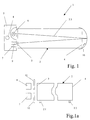
- a gas analyzer (here without evaluation electronics 20) referred to, which consists of a preferably cylindrical measuring cell as measuring cell 2, which is closed on both sides by two cell windows 3 and 4.
- the cell window 3, 4 are made of a material permeable to IR radiation.
- the cylindrical measuring cell 2 has an inlet pipe 2.1 and in a known manner Outlet pipe 2.2 for a sample gas, which for the sake of clarity only in Fig. 1a closer are shown.
- a carrier 5 is arranged on the cell window 3, on which there is a radiator 6 and a receiver 7 are in close proximity to the radiator 6.
- the carrier 5 is there a thermally stabilized metal element, on which an additional heating and control element 8, for example a transistor, is applied as direct heating.
- IR component for example an IR photodiode 9, in the immediate vicinity of the receiver 7 provided and preferably applied to the carrier 5.
- IR component for example an IR photodiode 9
- the carrier 5 At the cell window 3 opposite side of the measuring cell 2 is located behind the cell window 4 spherical mirror 10. This can also be a direct component of the measuring cell 2.
- a sample or test gas is admitted through the inlet pipe 2.1 into the measuring cell 2.
- An IR radiation emitted by the radiator 6 and, for example, chopped by a chopper blade 11 (FIG. 1 a) arrives in the measuring cell 2 and then through the sample gas.
- the IR radiation passes through an absorption section 2.3 within the measuring cell 2 twice, the IR radiation being attenuated twice in a known manner by the components of the sample gas.
- the spherical mirror 10 itself results in a general increase in the intensity of the attenuated IR radiation by bundling the same onto the receiver 7.
- a plurality of filters 12 are arranged between the measuring cell 2 and the receiver 7.
- the attenuated IR radiation allows only the wavelengths of the gas component to be measured to pass through the filters 12 used.
- This IR radiation transmitted through the filter 12 is received by the receiver 7, it being known that each gas has a different wavelength, which is converted into an equivalent signal.
- the CO 2 gas has a wavelength ⁇ of 4.25 or 4.41 ⁇ m and the CO gas has a wavelength ⁇ of 4.64 ⁇ m.
- the radiator 6 can also be flashed, the IR radiation being off the radiator 6 is emitted flashing.
- the temperature of the carrier 5 and thus of the radiator is controlled by the heating and regulating element 8 directly attached to the carrier 5 via a control circuit (not shown) 6 and the receiver 7 are preferably kept constant at approximately 55 ° C., the natural heat of the radiator 6 also being taken into account.
- the radiator temperature is measured via the IR photodiode 9 and made available as a reference signal for the radiation power actually generated by the radiator 6, as a result of which the radiator 6 is checked at the same time.
- the switch-on point and the end point of the radiator power are determined in order to compensate for this in the subsequent evaluation.
- the radiation power is preferably measured in a shorter-wave range (1 .mu.m to 2.5 .mu.m) in which the change in the radiator temperature is noticeably more noticeable than in the longer-wave actual measuring range.
- the sensitivity of the IR photodiode 9 is tuned to this wave range, for example delivering a high signal with low energy.
- the signals measured at the receiver 7 are very small and, as is known, must be amplified from approx. 100 ⁇ V to approx. 4 V for an evaluation.
- these signals are given to a plurality of, at least two amplifier stages 21, 22 of an analog signal processing 25 connected in series.
- an AC coupling C 1 of the amplifier stages 21, 22 is preferably carried out with one another (FIG. 2).
- the voltage level corresponding to the lowest radiator temperature is determined at the receiver 7 and clamped onto the input of the amplifier stage 21 as a defined input signal value.
- the clamping is switched off via the switch S 1 , so that only the AC coupling via the capacitor C 1 remains between the amplifier stages 21, 22, which results in an amplification which is independent of the absolute signal level of the receiver signal.
- the device consists of two separate ones Assemblies built, an optics / analog part 13 and a digital part 14.
- the optics / analog part 13 consists of the measuring cell 2, the carrier 5 with its applied Components and the entire analog signal processing, not shown here 25 including the AD and DA converters, not shown.
- a parameter memory 26 for example an EEPROM, on this optics / analog part 13, in which all optics and analog parameters are saved.
- the digital part 14 is completely independent of that operated optical / analog part 13, whereby each balanced optical / analog part 13 with each digital part 14 can be combined.
- the measuring cell 2 can have 9 mirrors instead of just one spherical mirror for a multiple pass of the IR radiation, in which case the radiator 6 from Receiver 7 is arranged somewhat away on the carrier 5, so another mirror is preferably is arranged between the two, but within the measuring cell 2.
Landscapes
- Physics & Mathematics (AREA)
- Spectroscopy & Molecular Physics (AREA)
- Health & Medical Sciences (AREA)
- Life Sciences & Earth Sciences (AREA)
- Chemical & Material Sciences (AREA)
- Analytical Chemistry (AREA)
- Biochemistry (AREA)
- General Health & Medical Sciences (AREA)
- General Physics & Mathematics (AREA)
- Immunology (AREA)
- Pathology (AREA)
- Investigating Or Analysing Materials By Optical Means (AREA)
Applications Claiming Priority (2)
| Application Number | Priority Date | Filing Date | Title |
|---|---|---|---|
| DE19929034 | 1999-06-25 | ||
| DE19929034A DE19929034A1 (de) | 1999-06-25 | 1999-06-25 | Vorrichtung zur Analyse einer Gasprobe mittels Infrarot-Absorption |
Publications (3)
| Publication Number | Publication Date |
|---|---|
| EP1063518A2 true EP1063518A2 (fr) | 2000-12-27 |
| EP1063518A3 EP1063518A3 (fr) | 2001-11-07 |
| EP1063518B1 EP1063518B1 (fr) | 2005-04-27 |
Family
ID=7912436
Family Applications (1)
| Application Number | Title | Priority Date | Filing Date |
|---|---|---|---|
| EP00111529A Expired - Lifetime EP1063518B1 (fr) | 1999-06-25 | 2000-05-30 | Appareil pour analyser un échantillon gazeux par l'absorption d'infrarouge |
Country Status (3)
| Country | Link |
|---|---|
| EP (1) | EP1063518B1 (fr) |
| AT (1) | ATE294381T1 (fr) |
| DE (2) | DE19929034A1 (fr) |
Cited By (1)
| Publication number | Priority date | Publication date | Assignee | Title |
|---|---|---|---|---|
| WO2009121089A1 (fr) * | 2008-04-04 | 2009-10-08 | Nanoident Technologies Ag | Système modulaire de mesure d'absorption |
Families Citing this family (5)
| Publication number | Priority date | Publication date | Assignee | Title |
|---|---|---|---|---|
| CN101592602B (zh) * | 2008-05-28 | 2011-04-20 | 北京市加华博来科技有限公司 | 高灵敏度、高稳定性的红外瓦斯传感器系统 |
| CN101592600B (zh) * | 2008-05-28 | 2011-04-20 | 北京市加华博来科技有限公司 | 高灵敏度快速响应红外瓦斯传感器 |
| CN101592603B (zh) * | 2008-05-29 | 2011-01-12 | 北京市加华博来科技有限公司 | 低能耗红外瓦斯传感器 |
| DE102009012767B4 (de) * | 2009-03-12 | 2013-05-23 | Texas Instruments Deutschland Gmbh | Geschaltete Spannungsversorgung mit Stromabtastung |
| DE102012215660B4 (de) | 2012-09-04 | 2014-05-08 | Robert Bosch Gmbh | Optische Gassensorvorrichtung und Verfahren zum Bestimmen der Konzentration eines Gases |
Family Cites Families (6)
| Publication number | Priority date | Publication date | Assignee | Title |
|---|---|---|---|---|
| US4358679A (en) * | 1980-09-02 | 1982-11-09 | Astro Safety Products Inc. | Calibration of analyzers employing radiant energy |
| US4596975A (en) * | 1984-05-31 | 1986-06-24 | Sierra Monitor Corporation | Thermally insulative mounting with solid state device |
| US4678904A (en) * | 1984-07-06 | 1987-07-07 | Technology Dynamics, Inc. | Optical measuring device using a spectral modulation sensor having an optically resonant structure |
| US5247185A (en) * | 1991-10-28 | 1993-09-21 | Critikon, Inc. | Regulated infrared source |
| US5747808A (en) * | 1994-02-14 | 1998-05-05 | Engelhard Sensor Technologies | NDIR gas sensor |
| DE19731241C2 (de) * | 1997-07-21 | 1999-09-23 | Fraunhofer Ges Forschung | Vorrichtung und Verfahren zur Bestimmung von Fluidkomponenten und Verfahren zur Herstellung der Vorrichtung |
-
1999
- 1999-06-25 DE DE19929034A patent/DE19929034A1/de not_active Ceased
-
2000
- 2000-05-30 AT AT00111529T patent/ATE294381T1/de not_active IP Right Cessation
- 2000-05-30 DE DE50010143T patent/DE50010143D1/de not_active Expired - Fee Related
- 2000-05-30 EP EP00111529A patent/EP1063518B1/fr not_active Expired - Lifetime
Cited By (2)
| Publication number | Priority date | Publication date | Assignee | Title |
|---|---|---|---|---|
| WO2009121089A1 (fr) * | 2008-04-04 | 2009-10-08 | Nanoident Technologies Ag | Système modulaire de mesure d'absorption |
| US9562847B2 (en) | 2008-04-04 | 2017-02-07 | Asmag-Holding Gmbh | Modular absorption measuring system |
Also Published As
| Publication number | Publication date |
|---|---|
| EP1063518A3 (fr) | 2001-11-07 |
| DE19929034A1 (de) | 2000-12-28 |
| DE50010143D1 (de) | 2005-06-02 |
| EP1063518B1 (fr) | 2005-04-27 |
| ATE294381T1 (de) | 2005-05-15 |
Similar Documents
| Publication | Publication Date | Title |
|---|---|---|
| EP0874233B1 (fr) | Capteur permettant une détection sélective de gaz | |
| DE68924163T2 (de) | Verfahren und vorrichtung zur spektroskopischen messung der gaskonzentration. | |
| DE19940280C2 (de) | Gassensor mit offener optischer Meßstrecke | |
| DE3688349T2 (de) | System zur chemischen Fernanalyse. | |
| EP1183520A2 (fr) | Dispositif de capteur de gaz | |
| EP3559634B1 (fr) | Procédé de correction de la longueur d'onde et de la gamme d'accord d'un spectromètre à laser | |
| DE102009025147B3 (de) | Verfahren zum Betrieb eines Spektrometers zur Gasanalyse, sowie Spektrometer selbst | |
| DE2365605A1 (de) | Kompensation gegenseitiger stoerung mehrerer spektralkomponenten | |
| EP3798611B1 (fr) | Procédé et analyseur de gaz permettant de mesurer la concentration d'un composant gazeux dans un gaz mesuré | |
| DE2438294A1 (de) | Verfahren zur messung kleiner gaskonzentrationen | |
| WO2013127657A1 (fr) | Procédé de mesure de la concentration d'une composante gazeuse dans un gaz de mesure et spectromètre laser | |
| EP3112846B1 (fr) | Procede de determination de la concentration d'un composant gazeux et spectrometre associe | |
| WO2000011452A1 (fr) | Dispositif et procede photometriques permettant de determiner le pouvoir calorifique d'un gaz d'essai | |
| DE2363180C2 (de) | Reaktionskinetisches Meßgerät | |
| DE4122572A1 (de) | Verfahren zum betrieb einer laserdiode | |
| EP3104163B1 (fr) | Analyseur de gaz de processus et procédé d'analyse d'un gaz de processus | |
| EP1063518B1 (fr) | Appareil pour analyser un échantillon gazeux par l'absorption d'infrarouge | |
| DE102011080086B4 (de) | Verfahren zur Messung der Konzentration einer Gaskomponente in einem Messgas | |
| DE102016108267A1 (de) | Vorrichtung und Verfahren zum Ermitteln einer Konzentration von wenigstens einer Gaskomponente eines Gasgemischs | |
| DE3106441C2 (de) | Verfahren zur quantitativen Bestimmung von Elementen durch Zeeman-Atomabsorptionsspektrometrie und Zeeman-Atomabsorptionsspektrometer | |
| EP0443702A2 (fr) | Procédé de mesure pour déterminer de petites absorptions de lumière | |
| DE102004031643A1 (de) | Nichtdispersiver Infrarot-Gasanalysator | |
| EP2899533A1 (fr) | Procédé de spectroscopie de modulation de la longueur d'onde avec un filtre pour le signal démodulé de mesure et le signal simulé | |
| EP0629851A2 (fr) | Dispositif pour analyse de traces de gaz par spectroscopie d'absorption | |
| DE68923966T2 (de) | Schaltung zur steuerung des einstellungspunktes in einer infrarot-gasanalysiervorrichtung. |
Legal Events
| Date | Code | Title | Description |
|---|---|---|---|
| PUAI | Public reference made under article 153(3) epc to a published international application that has entered the european phase |
Free format text: ORIGINAL CODE: 0009012 |
|
| 17P | Request for examination filed |
Effective date: 20000530 |
|
| AK | Designated contracting states |
Kind code of ref document: A2 Designated state(s): AT BE CH CY DE DK ES FI FR GB GR IE IT LI LU MC NL PT SE Kind code of ref document: A2 Designated state(s): AT DE FR GB IT |
|
| AX | Request for extension of the european patent |
Free format text: AL;LT;LV;MK;RO;SI |
|
| PUAL | Search report despatched |
Free format text: ORIGINAL CODE: 0009013 |
|
| AK | Designated contracting states |
Kind code of ref document: A3 Designated state(s): AT BE CH CY DE DK ES FI FR GB GR IE IT LI LU MC NL PT SE |
|
| AX | Request for extension of the european patent |
Free format text: AL;LT;LV;MK;RO;SI |
|
| AKX | Designation fees paid |
Free format text: AT DE FR GB IT |
|
| 17Q | First examination report despatched |
Effective date: 20040308 |
|
| GRAP | Despatch of communication of intention to grant a patent |
Free format text: ORIGINAL CODE: EPIDOSNIGR1 |
|
| GRAS | Grant fee paid |
Free format text: ORIGINAL CODE: EPIDOSNIGR3 |
|
| GRAA | (expected) grant |
Free format text: ORIGINAL CODE: 0009210 |
|
| AK | Designated contracting states |
Kind code of ref document: B1 Designated state(s): AT DE FR GB IT |
|
| REG | Reference to a national code |
Ref country code: GB Ref legal event code: FG4D Free format text: NOT ENGLISH |
|
| GBT | Gb: translation of ep patent filed (gb section 77(6)(a)/1977) |
Effective date: 20050427 |
|
| PG25 | Lapsed in a contracting state [announced via postgrant information from national office to epo] |
Ref country code: AT Free format text: LAPSE BECAUSE OF NON-PAYMENT OF DUE FEES Effective date: 20050530 |
|
| REF | Corresponds to: |
Ref document number: 50010143 Country of ref document: DE Date of ref document: 20050602 Kind code of ref document: P |
|
| PLBE | No opposition filed within time limit |
Free format text: ORIGINAL CODE: 0009261 |
|
| STAA | Information on the status of an ep patent application or granted ep patent |
Free format text: STATUS: NO OPPOSITION FILED WITHIN TIME LIMIT |
|
| ET | Fr: translation filed | ||
| 26N | No opposition filed |
Effective date: 20060130 |
|
| PGFP | Annual fee paid to national office [announced via postgrant information from national office to epo] |
Ref country code: IT Payment date: 20090527 Year of fee payment: 10 Ref country code: FR Payment date: 20090519 Year of fee payment: 10 |
|
| PGFP | Annual fee paid to national office [announced via postgrant information from national office to epo] |
Ref country code: GB Payment date: 20090528 Year of fee payment: 10 Ref country code: DE Payment date: 20090727 Year of fee payment: 10 |
|
| GBPC | Gb: european patent ceased through non-payment of renewal fee |
Effective date: 20100530 |
|
| REG | Reference to a national code |
Ref country code: FR Ref legal event code: ST Effective date: 20110131 |
|
| PG25 | Lapsed in a contracting state [announced via postgrant information from national office to epo] |
Ref country code: IT Free format text: LAPSE BECAUSE OF NON-PAYMENT OF DUE FEES Effective date: 20100530 |
|
| PG25 | Lapsed in a contracting state [announced via postgrant information from national office to epo] |
Ref country code: DE Free format text: LAPSE BECAUSE OF NON-PAYMENT OF DUE FEES Effective date: 20101201 |
|
| PG25 | Lapsed in a contracting state [announced via postgrant information from national office to epo] |
Ref country code: FR Free format text: LAPSE BECAUSE OF NON-PAYMENT OF DUE FEES Effective date: 20100531 |
|
| PG25 | Lapsed in a contracting state [announced via postgrant information from national office to epo] |
Ref country code: GB Free format text: LAPSE BECAUSE OF NON-PAYMENT OF DUE FEES Effective date: 20100530 |