EP1063724A1 - Connexion de sertissage - Google Patents
Connexion de sertissage Download PDFInfo
- Publication number
- EP1063724A1 EP1063724A1 EP00112895A EP00112895A EP1063724A1 EP 1063724 A1 EP1063724 A1 EP 1063724A1 EP 00112895 A EP00112895 A EP 00112895A EP 00112895 A EP00112895 A EP 00112895A EP 1063724 A1 EP1063724 A1 EP 1063724A1
- Authority
- EP
- European Patent Office
- Prior art keywords
- crimp connection
- wire
- wire claw
- claw
- crimp
- Prior art date
- Legal status (The legal status is an assumption and is not a legal conclusion. Google has not performed a legal analysis and makes no representation as to the accuracy of the status listed.)
- Withdrawn
Links
- 210000000078 claw Anatomy 0.000 claims abstract description 107
- 239000004020 conductor Substances 0.000 claims abstract description 6
- 239000000463 material Substances 0.000 claims description 14
- 238000005452 bending Methods 0.000 claims description 13
- 238000007373 indentation Methods 0.000 claims description 3
- 230000000149 penetrating effect Effects 0.000 abstract 1
- 238000004049 embossing Methods 0.000 description 11
- 238000010586 diagram Methods 0.000 description 10
- 230000006835 compression Effects 0.000 description 9
- 238000007906 compression Methods 0.000 description 9
- 238000012360 testing method Methods 0.000 description 8
- 238000000418 atomic force spectrum Methods 0.000 description 4
- 238000000034 method Methods 0.000 description 4
- 238000004519 manufacturing process Methods 0.000 description 3
- 238000012544 monitoring process Methods 0.000 description 2
- 210000003462 vein Anatomy 0.000 description 2
- 229910000851 Alloy steel Inorganic materials 0.000 description 1
- 238000011161 development Methods 0.000 description 1
- 230000018109 developmental process Effects 0.000 description 1
- 238000011156 evaluation Methods 0.000 description 1
Images



Classifications
-
- H—ELECTRICITY
- H01—ELECTRIC ELEMENTS
- H01R—ELECTRICALLY-CONDUCTIVE CONNECTIONS; STRUCTURAL ASSOCIATIONS OF A PLURALITY OF MUTUALLY-INSULATED ELECTRICAL CONNECTING ELEMENTS; COUPLING DEVICES; CURRENT COLLECTORS
- H01R4/00—Electrically-conductive connections between two or more conductive members in direct contact, i.e. touching one another; Means for effecting or maintaining such contact; Electrically-conductive connections having two or more spaced connecting locations for conductors and using contact members penetrating insulation
- H01R4/10—Electrically-conductive connections between two or more conductive members in direct contact, i.e. touching one another; Means for effecting or maintaining such contact; Electrically-conductive connections having two or more spaced connecting locations for conductors and using contact members penetrating insulation effected solely by twisting, wrapping, bending, crimping, or other permanent deformation
- H01R4/18—Electrically-conductive connections between two or more conductive members in direct contact, i.e. touching one another; Means for effecting or maintaining such contact; Electrically-conductive connections having two or more spaced connecting locations for conductors and using contact members penetrating insulation effected solely by twisting, wrapping, bending, crimping, or other permanent deformation by crimping
- H01R4/183—Electrically-conductive connections between two or more conductive members in direct contact, i.e. touching one another; Means for effecting or maintaining such contact; Electrically-conductive connections having two or more spaced connecting locations for conductors and using contact members penetrating insulation effected solely by twisting, wrapping, bending, crimping, or other permanent deformation by crimping for cylindrical elongated bodies, e.g. cables having circular cross-section
- H01R4/184—Electrically-conductive connections between two or more conductive members in direct contact, i.e. touching one another; Means for effecting or maintaining such contact; Electrically-conductive connections having two or more spaced connecting locations for conductors and using contact members penetrating insulation effected solely by twisting, wrapping, bending, crimping, or other permanent deformation by crimping for cylindrical elongated bodies, e.g. cables having circular cross-section comprising a U-shaped wire-receiving portion
Definitions
- the invention relates to a crimp connection on an electrical component for connecting at least one strand of an electrical conductor the component, with a contact web, and with one projecting from the contact web Wire claw, which merges with its flat sides into the contact bridge and to clamp the strand on the contact web in the direction of Contact web is bendable. Furthermore, the invention relates to an electrical Component with such a crimp connection.
- Such a crimp connection is often used on electronic components for connecting electrical conductors.
- this type of crimp connections there is the problem that with a given material thickness of the wire claw only one strand with a sufficiently high cross-sectional diameter can be clamped, since otherwise there is a risk that the clamping force with which the strand in the crimp connection between the wire claw and the contact web is clamped, is not sufficient to prevent the wire from coming loose from the crimp connection.
- a stranded wire whose cross-sectional area must not be less than 0.5 mm 2 can be clamped.
- the compressive force component that is to say the percentage difference between the deforming force used when deforming a crimp connection with an inserted strand and the deforming force required when deforming a crimp connection without an inserted strand, is below a minimum permissible limit value of usually 10% falls, which must at least be given for monitoring an automatic deformation process.
- the invention solves the problem by a crimp connection with the Features according to claim 1 and in particular in that the wire claw at least one continuous extending between the flat sides Has recess.
- the invention also achieves the object by an electrical component with the features of claim 11.
- the recess formed on the wire claw achieved that the resulting during the deformation process Tensions in the material run in a defined direction and that material arranged in the bending line in a predetermined direction is deformed. Furthermore, the material of the wire claw according to the invention due to the same material thickness compared to a conventional wire claw less stiffness deformed more so that after removal the resilience of the external deforming forces wire claw according to the invention is less than in the conventional Wire claw.
- the wire claw according to the invention lies after the Bending with greater pretensioning force on the between the contact web and the wire claw clamped wire, so that the clamping force on the Strand compared to that of a conventional wire claw Clamping force is higher and also strands with a small cross-sectional area can be securely clamped. Furthermore, the compression force component lies even with strands with a small cross-sectional area above the minimum value to be recorded of 10%, as test series have shown so that the crimp connections according to the invention also in their automatic production can be monitored.
- the recess in a section of the wire claw by making the greatest deformations when bending the wire claw occur. In this way it is achieved that the material in particular in the area of the bending line through the recess accordingly is reduced and the material by a corresponding deformation forces receives a high degree of deformation through which the springback effect after removal of the deformation forces is low.
- the recess is a preferred one square window.
- they lie deformation forces required for reshaping the crimp connection with a vein claw designed in this way by about 20% below that for one conventional wire claw forces.
- the pull-out force required to pull the wire out of the crimp connection is required above the pull-out force required for a crimp connection can be achieved with a conventionally designed wire claw can.
- the compression force component is about 30%, so that the production of the crimp connections can also be easily monitored.
- the recess be designed as a slot preferably runs transversely to the bending line of the recess.
- the Compression force component that can be realized with the crimp connection according to the invention greater than the amount of compressive force that a conventional Crimp connection can be achieved, so that a proper one Monitoring the deformation process of the crimp connection is possible.
- the recess is designed as a circular or oval opening. Similar results have also been achieved in this embodiment leave, as was determined in several test series.
- a material is proposed as the material for the crimp connection, the tensile strength Rm of which is in a range from approximately 250 to 800 N / mm 2 , preferably approximately 760 N / mm 2 , since such a material withstands the forces which arise on the wire claw during the deformation process can and the wire claw does not tear or break even in the area of greatest deformation.
- FIG. 1 shows a first exemplary embodiment of a crimp connection 10 in perspective representation, which on an electrical component (not shown) such as a socket or a plug pin is provided.
- the crimp connection 10 has a contact web 12, which is electrically conductively connected to the component and to the component
- a wire claw 14 or 16 is integrally formed on the longitudinal edges. Every wire claw 14 and 16 is approximately rectangular in shape and has between them Flat sides on a square recess 18 and 20 respectively.
- the square Recess 18 or 20 is symmetrical between the side edges the wire claw 14 and 16 arranged and lies in a section of Wire claw 14 or 16, in which when bending the wire claw 14 or 16 the greatest deformation occurs.
- each square recess 18 and 20 groove-shaped indentation 22 formed On the facing flat sides of the two wire claws 14 and 16 is one on both sides of each square recess 18 and 20 groove-shaped indentation 22 formed, of which only the left in Fig. 1 shown can be seen.
- the groove-shaped impressions 22 run transverse to the bending lines of the wire claws 14 and 16 from one flat side the wire claw 14 to the other flat side of the wire claw 16.
- the crimp connection are on the flat sides the wire claws 14 and 16 no impressions formed.
- the crimp connection 30 also has one here Contact web 32, from the two longitudinal edges of wire claws 34th and 36 stand out.
- Contact web 32 from the two longitudinal edges of wire claws 34th and 36 stand out.
- In this embodiment are as recesses on each wire claw 34 and 36 two in parallel at a distance from each other extending slots 38 and 40 or 42 and 44 formed, with groove-shaped embossments on the facing flat sides of the Wire claws 34 and 36 were dispensed with.
- FIG. 3 shows a third embodiment of a crimp connection 50 in perspective view shown.
- the crimp connection is also in this case 50 formed from a contact web 32, from the longitudinal edges two wire claws 54 and 56 protrude.
- a circular recess 58 or 60 is formed approximately in the middle, which in the section of the wire claw 54 or 56 is formed, which is when bending is deformed the most.
- On both sides of the circular recesses 58 and 60 is on the facing flat sides of the Core claws 54 and 56 each have a groove-shaped indentation 62 and 64 formed, which extends transversely to the bending line of the wire claws 54 and 56 and ends near the free end of each wire claw 54 or 56.
- the mutually facing flat sides of the wire claws 54 and 56 without impressions educated.
- the two cutouts 58 and 60 facilitate deformation the wire claws 54 and 56 when the strand (not shown) through the Wire claws 54 and 56 are to be clamped on the contact web 52.
- crimp connections were tested, which also with a thus designed wire claw were provided, one in each wire claw square window was formed, as in that shown in Fig. 1 Embodiment.
- wire claws with and without internal embossing checked.
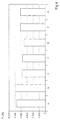
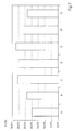
- 4, 5 and 7 are the test results for crimp connections with a wire claw without internal embossing with C and for crimp connections with a wire claw with internal embossing marked with D.
- Fig. 4 shows a diagram in which the deformation forces required for deformation for the various crimp connections tested are. It is striking that to deform the crimp connections A and B with wire claws without recesses about 20% higher deformation forces were required to deform the wire claws than for deforming the five other crimp connections tested in the comparison C to G with cutouts on the wire claws.
- FIG. 6 shows a force-time diagram in which the general relationship between the force profile of the deformation force F V during the deformation of a crimp connection into which a stranded wire has been inserted and the force profile of a deformation force F V0 during the deformation a crimp connection is shown without inserted wire.
- This percentage difference also called headroom, referred to as the compressive force component X
- This percentage difference should usually not fall below a value of 10%, since from this percentage fluctuations in the deformation force are greater than changes in force due to crimp errors, such as missing strands, so that a correct evaluation of whether the Crimp connection has been carried out properly, is not possible.
- the compression force component X gives an indication of whether the strand has been clamped sufficiently strong because of the amount of compressive force X is roughly proportional to the difference between the deformation forces on the wire claw and the deformation force on the strand. It has been found that with a compression force component X, which is less than or equal to 5%, a secure crimp connection is not guaranteed and the automated creation of the crimp connection is not can be monitored. Conditional security of the crimp connection is given if the compressive force component X is in the range from 5 to 15 % lies. If the compression force component X is in a range of over 15 % or significantly above, can be from a secure crimp connection sufficiently high clamping force can be assumed for the stranded wire can be monitored well during automated production.
- FIG. 7 shows a diagram in which the different compressive force components X of the different crimp connections A to G in Comparison are shown. It was found that in particular the Crimp connections C, D and E, whose wire claws with square Windows or slits were a particularly high proportion of compressive force X while the crimp connections with Standard claws have less than 12% less compression force X owned. Also the two crimp connections, their wire claws were provided with circular recesses Compression force proportions X each have percentages that correspond to the Standard crimp connections achievable percentages of compressive force X were comparable, so that here too a sufficient Security of the crimp connections was given.
Landscapes
- Connections Effected By Soldering, Adhesion, Or Permanent Deformation (AREA)
Applications Claiming Priority (2)
| Application Number | Priority Date | Filing Date | Title |
|---|---|---|---|
| DE1999129004 DE19929004A1 (de) | 1999-06-24 | 1999-06-24 | Crimpverbindung |
| DE19929004 | 1999-06-24 |
Publications (1)
| Publication Number | Publication Date |
|---|---|
| EP1063724A1 true EP1063724A1 (fr) | 2000-12-27 |
Family
ID=7912413
Family Applications (1)
| Application Number | Title | Priority Date | Filing Date |
|---|---|---|---|
| EP00112895A Withdrawn EP1063724A1 (fr) | 1999-06-24 | 2000-06-19 | Connexion de sertissage |
Country Status (2)
| Country | Link |
|---|---|
| EP (1) | EP1063724A1 (fr) |
| DE (1) | DE19929004A1 (fr) |
Cited By (1)
| Publication number | Priority date | Publication date | Assignee | Title |
|---|---|---|---|---|
| WO2012137989A1 (fr) * | 2011-04-06 | 2012-10-11 | Yazaki Corporation | Cosse de protection pour câble coaxial |
Families Citing this family (2)
| Publication number | Priority date | Publication date | Assignee | Title |
|---|---|---|---|---|
| DE10253977A1 (de) * | 2002-11-20 | 2003-12-18 | Bosch Gmbh Robert | Crimpverbindung |
| DE102006013347B4 (de) | 2006-03-23 | 2022-12-22 | Kostal Kontakt Systeme Gmbh | Steckverbinderanordnung |
Citations (5)
| Publication number | Priority date | Publication date | Assignee | Title |
|---|---|---|---|---|
| DE1540640A1 (de) * | 1958-10-15 | 1969-08-21 | Amp Inc | Kugelkopfstecker |
| US3662089A (en) * | 1969-11-13 | 1972-05-09 | Post Office | Modifications of wire connectors |
| US3812448A (en) * | 1972-11-24 | 1974-05-21 | Thomas & Betts Corp | Electrical connector |
| GB1537493A (en) * | 1976-04-02 | 1978-12-29 | Ross Courtney & Co Ltd | Electrical connector tags |
| EP0793311A2 (fr) * | 1996-03-01 | 1997-09-03 | Molex Incorporated | Système pour terminer le blindage d'un câble à grande vitesse |
Family Cites Families (4)
| Publication number | Priority date | Publication date | Assignee | Title |
|---|---|---|---|---|
| DE1150730B (de) * | 1961-10-11 | 1963-06-27 | Amp Inc | Wendelfoermige Anschlussklemme fuer einen elektrischen Leiter |
| DE1515774B1 (de) * | 1965-08-03 | 1971-02-25 | Grote & Hartmann | Verfahren zur Herstellung eines mit einem lackisolierten,elektrischen Leiter kontaktgebenden Krallenverbinders |
| CA1189690A (fr) * | 1981-07-20 | 1985-07-02 | Paul E. O'donnell | Connecteur electrique a sertir, avec joint anaerobie |
| DE19549174A1 (de) * | 1995-10-28 | 1997-07-03 | Bosch Gmbh Robert | Kontaktelement mit Crimpabschnitt |
-
1999
- 1999-06-24 DE DE1999129004 patent/DE19929004A1/de not_active Withdrawn
-
2000
- 2000-06-19 EP EP00112895A patent/EP1063724A1/fr not_active Withdrawn
Patent Citations (5)
| Publication number | Priority date | Publication date | Assignee | Title |
|---|---|---|---|---|
| DE1540640A1 (de) * | 1958-10-15 | 1969-08-21 | Amp Inc | Kugelkopfstecker |
| US3662089A (en) * | 1969-11-13 | 1972-05-09 | Post Office | Modifications of wire connectors |
| US3812448A (en) * | 1972-11-24 | 1974-05-21 | Thomas & Betts Corp | Electrical connector |
| GB1537493A (en) * | 1976-04-02 | 1978-12-29 | Ross Courtney & Co Ltd | Electrical connector tags |
| EP0793311A2 (fr) * | 1996-03-01 | 1997-09-03 | Molex Incorporated | Système pour terminer le blindage d'un câble à grande vitesse |
Cited By (4)
| Publication number | Priority date | Publication date | Assignee | Title |
|---|---|---|---|---|
| WO2012137989A1 (fr) * | 2011-04-06 | 2012-10-11 | Yazaki Corporation | Cosse de protection pour câble coaxial |
| CN103477499A (zh) * | 2011-04-06 | 2013-12-25 | 矢崎总业株式会社 | 用于同轴电缆的屏蔽端子 |
| CN103477499B (zh) * | 2011-04-06 | 2016-01-27 | 矢崎总业株式会社 | 用于同轴电缆的屏蔽端子 |
| US9325082B2 (en) | 2011-04-06 | 2016-04-26 | Yazaki Corporation | Crimped terminal for coaxial cable |
Also Published As
| Publication number | Publication date |
|---|---|
| DE19929004A1 (de) | 2000-12-28 |
Similar Documents
| Publication | Publication Date | Title |
|---|---|---|
| DE10231887B4 (de) | Krimpanschlußklemme | |
| DE69911911T2 (de) | Crimpanschlussklemme für flexible Leiterplatte und Crimpanordnung für Leitungsader | |
| DE69700563T2 (de) | Steckerelement und Herstellungsverfahren dafür | |
| DE3110144A1 (de) | Elektrischer verbinder fuer nicht abisolierte leiter | |
| DE2637378C2 (de) | Verbinderkontakt | |
| EP0823752A2 (fr) | Connecteur à ressort pour conducteur électrique | |
| DE10250924A1 (de) | Inline-Klemmverbinder für Flex-Flachbandkabel | |
| DE2545011A1 (de) | Anwuergverbindung und verfahren zu ihrer herstellung | |
| DE2342408C3 (fr) | ||
| DE19809706B4 (de) | Quetschklemme | |
| DE2055583C3 (de) | Verbindungsklemme zum Andrücken an elektrische Drähte | |
| DE202010003385U1 (de) | Elektrische Anschlussklemme | |
| DE102016105192B3 (de) | Leiteranschlussklemme | |
| DE69913397T2 (de) | Schneidklemme | |
| DE4320539C2 (de) | Leitungsdraht-Verbindungsklemme | |
| EP2230732B1 (fr) | Dispositif pour sertir un conducteur sur un élément de connexion | |
| DE2653357A1 (de) | Klemmelement zum abisolierfreien anschluss elektrischer leiter | |
| DE19929004A1 (de) | Crimpverbindung | |
| DE69601109T2 (de) | Verbindungsanordnung, sein Herstellverfahren, und elektrische Vorrichtung mit einem solchen Verbindungsanordnung | |
| DE69806205T2 (de) | Geschlitzte Anschlussklemme für eine Verbindungsanordnung für mindestens eine elektrische Leiter | |
| DE102004023850B4 (de) | Presssitz-Setzwerkzeug für einen Verbinder | |
| DE10200282A1 (de) | Selbsttätig abisolierendes Anschlusselement mit einem konvergierenden Schlitz | |
| EP0675564B1 (fr) | Contact auto-dénudant oblique | |
| DE3637626C2 (de) | Verfahren zum Festlegen eines Metallstifts innerhalb eines keramischen Isolierkörpers | |
| DE102020003770A1 (de) | Elektrischer Kontakt |
Legal Events
| Date | Code | Title | Description |
|---|---|---|---|
| PUAI | Public reference made under article 153(3) epc to a published international application that has entered the european phase |
Free format text: ORIGINAL CODE: 0009012 |
|
| AK | Designated contracting states |
Kind code of ref document: A1 Designated state(s): DE ES FR GB IT |
|
| AX | Request for extension of the european patent |
Free format text: AL;LT;LV;MK;RO;SI |
|
| 17P | Request for examination filed |
Effective date: 20010126 |
|
| 17Q | First examination report despatched |
Effective date: 20010611 |
|
| AKX | Designation fees paid |
Free format text: DE ES FR GB IT |
|
| STAA | Information on the status of an ep patent application or granted ep patent |
Free format text: STATUS: THE APPLICATION IS DEEMED TO BE WITHDRAWN |
|
| 18D | Application deemed to be withdrawn |
Effective date: 20011023 |