EP1064152B1 - Procede et appareil d'extraction d'une puce d'une tranche et de transport de ladite puce jusqu'a un point de collecte - Google Patents
Procede et appareil d'extraction d'une puce d'une tranche et de transport de ladite puce jusqu'a un point de collecte Download PDFInfo
- Publication number
- EP1064152B1 EP1064152B1 EP99908205A EP99908205A EP1064152B1 EP 1064152 B1 EP1064152 B1 EP 1064152B1 EP 99908205 A EP99908205 A EP 99908205A EP 99908205 A EP99908205 A EP 99908205A EP 1064152 B1 EP1064152 B1 EP 1064152B1
- Authority
- EP
- European Patent Office
- Prior art keywords
- component
- die
- conveyor
- head
- flexible film
- Prior art date
- Legal status (The legal status is an assumption and is not a legal conclusion. Google has not performed a legal analysis and makes no representation as to the accuracy of the status listed.)
- Expired - Lifetime
Links
Images









Classifications
-
- H—ELECTRICITY
- H10—SEMICONDUCTOR DEVICES; ELECTRIC SOLID-STATE DEVICES NOT OTHERWISE PROVIDED FOR
- H10P—GENERIC PROCESSES OR APPARATUS FOR THE MANUFACTURE OR TREATMENT OF DEVICES COVERED BY CLASS H10
- H10P72/00—Handling or holding of wafers, substrates or devices during manufacture or treatment thereof
- H10P72/04—Apparatus for manufacture or treatment
- H10P72/0442—Apparatus for placing on an insulating substrate, e.g. tape
-
- H—ELECTRICITY
- H10—SEMICONDUCTOR DEVICES; ELECTRIC SOLID-STATE DEVICES NOT OTHERWISE PROVIDED FOR
- H10P—GENERIC PROCESSES OR APPARATUS FOR THE MANUFACTURE OR TREATMENT OF DEVICES COVERED BY CLASS H10
- H10P72/00—Handling or holding of wafers, substrates or devices during manufacture or treatment thereof
- H10P72/04—Apparatus for manufacture or treatment
- H10P72/0428—Apparatus for mechanical treatment or grinding or cutting
-
- Y—GENERAL TAGGING OF NEW TECHNOLOGICAL DEVELOPMENTS; GENERAL TAGGING OF CROSS-SECTIONAL TECHNOLOGIES SPANNING OVER SEVERAL SECTIONS OF THE IPC; TECHNICAL SUBJECTS COVERED BY FORMER USPC CROSS-REFERENCE ART COLLECTIONS [XRACs] AND DIGESTS
- Y10—TECHNICAL SUBJECTS COVERED BY FORMER USPC
- Y10T—TECHNICAL SUBJECTS COVERED BY FORMER US CLASSIFICATION
- Y10T156/00—Adhesive bonding and miscellaneous chemical manufacture
- Y10T156/11—Methods of delaminating, per se; i.e., separating at bonding face
- Y10T156/1105—Delaminating process responsive to feed or shape at delamination
-
- Y—GENERAL TAGGING OF NEW TECHNOLOGICAL DEVELOPMENTS; GENERAL TAGGING OF CROSS-SECTIONAL TECHNOLOGIES SPANNING OVER SEVERAL SECTIONS OF THE IPC; TECHNICAL SUBJECTS COVERED BY FORMER USPC CROSS-REFERENCE ART COLLECTIONS [XRACs] AND DIGESTS
- Y10—TECHNICAL SUBJECTS COVERED BY FORMER USPC
- Y10T—TECHNICAL SUBJECTS COVERED BY FORMER US CLASSIFICATION
- Y10T156/00—Adhesive bonding and miscellaneous chemical manufacture
- Y10T156/19—Delaminating means
- Y10T156/1906—Delaminating means responsive to feed or shape at delamination
-
- Y—GENERAL TAGGING OF NEW TECHNOLOGICAL DEVELOPMENTS; GENERAL TAGGING OF CROSS-SECTIONAL TECHNOLOGIES SPANNING OVER SEVERAL SECTIONS OF THE IPC; TECHNICAL SUBJECTS COVERED BY FORMER USPC CROSS-REFERENCE ART COLLECTIONS [XRACs] AND DIGESTS
- Y10—TECHNICAL SUBJECTS COVERED BY FORMER USPC
- Y10T—TECHNICAL SUBJECTS COVERED BY FORMER US CLASSIFICATION
- Y10T156/00—Adhesive bonding and miscellaneous chemical manufacture
- Y10T156/19—Delaminating means
- Y10T156/1978—Delaminating bending means
- Y10T156/1983—Poking delaminating means
-
- Y—GENERAL TAGGING OF NEW TECHNOLOGICAL DEVELOPMENTS; GENERAL TAGGING OF CROSS-SECTIONAL TECHNOLOGIES SPANNING OVER SEVERAL SECTIONS OF THE IPC; TECHNICAL SUBJECTS COVERED BY FORMER USPC CROSS-REFERENCE ART COLLECTIONS [XRACs] AND DIGESTS
- Y10—TECHNICAL SUBJECTS COVERED BY FORMER USPC
- Y10T—TECHNICAL SUBJECTS COVERED BY FORMER US CLASSIFICATION
- Y10T29/00—Metal working
- Y10T29/49—Method of mechanical manufacture
- Y10T29/49815—Disassembling
- Y10T29/49819—Disassembling with conveying of work or disassembled work part
-
- Y—GENERAL TAGGING OF NEW TECHNOLOGICAL DEVELOPMENTS; GENERAL TAGGING OF CROSS-SECTIONAL TECHNOLOGIES SPANNING OVER SEVERAL SECTIONS OF THE IPC; TECHNICAL SUBJECTS COVERED BY FORMER USPC CROSS-REFERENCE ART COLLECTIONS [XRACs] AND DIGESTS
- Y10—TECHNICAL SUBJECTS COVERED BY FORMER USPC
- Y10T—TECHNICAL SUBJECTS COVERED BY FORMER US CLASSIFICATION
- Y10T29/00—Metal working
- Y10T29/49—Method of mechanical manufacture
- Y10T29/49815—Disassembling
- Y10T29/49822—Disassembling by applying force
- Y10T29/49824—Disassembling by applying force to elastically deform work part or connector
Definitions
- This invention relates generally to the manufacture of circuit boards, more particularly, the surface mounting of integrated circuits (ICs) on substrates including printed circuit boards and other platforms where components are mounted and connected. More particularly, the invention relates to a die feeder device that performs the function of removing each known good die from a sawed wafer disposed on a flexible adhesive film, placing the die on a conveyer, and conveying the die to a pick-up location.
- ICs integrated circuits
- tape feeders tape feeders
- An example of a reel type tape feeder is shown in U.S. Patent 4,437,232, issued to Araki et al. on March 20, 1984 .
- One advantage of the tape feeders is that they take up a small amount of space during the assembly of the circuit board, thus a large number of tape feeders can be placed adjacent to one another and utilized by a single assembly machine.
- tape feeders are relatively simple in operation and are capable of feeding die reliably at a very rapid pace.
- the present invention takes the place of these tape feeders and obviates the steps of placing die onto the plastic tape then removing them from the plastic tape.
- the present invention is capable of performing this function of presenting die serially directly from a wafer without taking up significantly more space than a tape feeder. For this reason, it is called a direct die feeder, or DDF.
- DDF direct die feeder
- US 4,876,791 describes apparatus for and methods of bonding a component to a substrate. More particularly, this invention relates to apparatus for and methods of removing small components, such as dies or other electrical components, from a wafer and bonding the components to a substrate.
- the present invention is, intended to replace current tape feeders, it is designed to maintain the narrow form-factor width standard of 80 mm which is standard in the industry.
- the narrow width enables many direct die feeders of the present invention to be positioned side by side (or along with tape feeders) and thus accessible by a single pick and place machine.
- By maintaining the narrow form-factor fewer pick and place machines are needed as well as fewer pick and place stations in the assembly line. This significantly affects the overall cost and time consumed in the production of each unit. Maintaining this narrow profile required many design innovations herein disclosed.
- the present invention represents a significant departure from the established practice of packaging dies in carrier tapes, shipping the die in the carrier tapes to a circuit board manufacturer, and then feeding the tapes to pick and place machines.
- each die is picked from the wafer and presented directly to the host automated pick and place machine via a conveyor.
- the feeder can also replace matrix trays to present parts to the host pick and place machine.
- the tray feeders represent a considerable expense as they take up a large section of the host machine interface as well as the cost of buying and stuffing trays.
- Wafers usable by this invention are provided in a manner which is standard in the industry.
- a wafer which has been etched to form the micro-electric circuitry thereon is placed on a flexible adhesive film which holds the wafer in place during a sawing (or "dicing") operation.
- the adhesive film is mounted in a ring which holds the flexible film during removal of the die.
- the wafer is "expanded", which means that the flexible adhesive film is stretched after dicing so that individual die spread out from one another.
- the mounting ring is used to maintain the flexible film in the stretched state.
- An expanded ring is characterized by an enlarged gap between adjacent dies, which improve the reliability of die extraction and prevents "chip-out” (damage to the picked die or adjacent die caused by scraping the die edges during pick-up).
- a machine vision system is employed by the present invention to perform die recognition using the die edges, which requires gaps between the die, permitting them to be perceived by a visual imaging apparatus.
- the gaps caused by the dicing operation, without further expansion, is often sufficient to enable the chips to be reliably recognized and removed by the present invention, although it is recommended that the wafer be expanded prior to removing die.
- U.S. Patent 4,876,791 to Michaud et al. discloses an apparatus for removing die from an expanded wafer and placing the die on a substrate.
- U.S. Patent 5,671,530 to combs et al. discloses an apparatus which removes die from an expanded wafer oriented vertically for use in the environment intended for the present invention.
- the present invention overcomes the disadvantages of the prior art noted above.
- the direct die feeder of the present invention takes the place of conventional tape and tray feeders, and is therefore compatible with existing assembly machinery.
- the use of the direct die feeder is not limited to feeding die; it can feed any type of component positioned on a flexible film.
- die generally refers to any type of component mounted to a flexible film.
- a novel conveyor belt die may be transported to the pickup location while the pick-head assembly is busy removing more die from the wafer.
- a novel flip head is selectively operable to accept a die from the pick head and then place the die in the flipped position on the conveyor.
- the pick head can place the die directly on the conveyor in the conventional orientation if required.
- the present invention is capable of presenting the die in the proper orientation for either the conventional or the flipped methods of mounting.
- the die conveyor extends substantially the full length of the feeder traversing the entire wafer. This feature minimizes pick head movement as it removes die from the wafer and places them at any convenient location on the conveyor.
- the pick head is thus limited to two short 10 mm strokes in order to remove and register a die to the transport system where the transportation of the die is done in parallel to the picking.
- Prior attempts have incorporated the transport system in the pick and place mechanism resulted in requiring the die to by moved 300 mm or more to their final destination which requires a very substantial mechanism to perform this movement quickly. Such a device would be too large and bulky to fit into the narrow form factor required by the industry.
- the reduced motion of the pick head of the present invention translates into rapid die removal from the wafer that operates in the narrow form factor and is energy efficient.
- the conveyor also facilitates buffering of die to the extraction point, which permits an assembly machine to take a cluster of die from the conveyor in rapid succession if it has that capability.
- an assembly machine By accepting a cluster of die in rapid succession using, for example, a rotary pick and place head assembly, the assembly machine can operate at peak efficiency. While the assembly machine is busy installing the chips on the circuit boards, the chip feeder will pick die off the wafer and place them on the conveyer, loading the conveyer for the mounting heads' return to take the next cluster of die from the feeder. Buffering of die also provides the practical advantage of being able to exchange wafers without shutting down the line.
- Fig. 1 shows the fully assembled direct die feeder 100 in a false-perspective, isometric view.
- Direct die feeder 100 includes a service access 94 which is transparent to allow viewing of the operation of the invention.
- Service access 94 pivots upward at hinge 95 to permit periodic maintenance and servicing of the moving parts inside.
- Cabinet 92 houses the control unit 101 and associated control systems, such as pneumatic control assembly 106.
- a control panel 96 shown in Figs. 1 and 37, is provided which controls the function of the apparatus, which can also be controlled remotely through a network connection.
- the direct die feeder 100 mounts to the host assembly machine using rails 90, which allow the direct die feeder to slide out from between other feeders making it accessible for servicing.
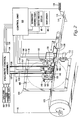
- Fig. 2 provides a schematic representation of the main working parts and control system of the invention.
- the major components of the invention include wafer frame 111, conveyor 170, die strip head 130, pick head 150, flip head 140, machine vision camera 160, and control unit 101.
- the basic operation of this system is best understood with reference to the schematic representation of the invention shown in Fig. 2, however reference should also be made to Figure 3 which shows the working parts after certain covers and components are removed.
- Fig. 2 incorporates the following conventions to clearly show the important moving parts of the invention:
- Each actuator is represented as a cylindrical body having rod extending therefrom which either translates along the axis of the cylindrical body or rotates on the axis of the cylindrical body.
- the motion of each actuator or the part it moves is indicated with an arrow near the actuator. Occasionally, the arrow is shown adjacent to the part actuated.
- Structural supports are represented with thick black lines.
- Wafer 105 is shown in phantom so that parts positioned behind the wafer, including die strip head 130, die strip head actuator 132, and associated control lines and support structures could be clearly shown. It should also be understood, however, that the wafer itself in not part of this invention.
- Wafer 105 is an expanded 8 inch wafer, however the frame 111 can also position other sized wafers, and the invention can be modified to accept larger wafers.
- Wafers are expanded by stretching the flexible film to which the sawed wafer is attached, causing each chip on the film to move away from its neighbors. Once the film is stretched, it is placed in a wafer ring 110 (see Fig. 38) which clamps the film between two component rings. Although recommended, wafers are often not required to be expanded prior to being loaded into direct die feeder 100 in order for the feeder to function properly. Regardless of whether the wafer is expanded, it must be supported in a ring 110 that is compatible with frame 111 of the device.
- wafer 105 is inserted through wafer access 113 in the direction of arrow 114, in a manner more particularly described below.
- Wafer 105 is positioned vertically in frame 111, but this is not a mandatory orientation. While the vertical orientation minimizes the horizontal reach of the profile, the frame can operate at any angle as it rotates on an axis that is parallel to conveyor 170.
- clamp 112 actuates to lock wafer 105 in place.
- control unit 101 shown in Fig. 2, which may consist of a general purpose computer system equipped with multiple i/o ports for sending and receiving signals from the various sensors and actuators.
- control unit 101 may consist of a general purpose computer system equipped with multiple i/o ports for sending and receiving signals from the various sensors and actuators.
- the signal pathways are each represented in Fig. 2 with a single fine line, it should be understood that each may consist of more than one electrical wire to and from each actuator or sensor, and in the case of actuators, the single line may also represent feedback lines from verification sensors.
- many of the actuators are electro-mechanical, but some are preferred to be pneumatically actuated.
- pneumatic control is effectuated through the use of control lines 135 which operate solenoid-controlled valves (not shown) in pneumatic control assembly 106, which connects each of pneumatic control lines 157 and 137 with either a vacuum source 107, ambient atmospheric pressure source 108, or compressed air source 109 as required.
- Control unit 101 receives input from a variety of sources, including an external advance signal generated by the host automated assembly machine 172, die placement sensor 176 which detects die when present at the extraction point, user input from keypad 96, door and service sensors 86, and video input signal 166 from video camera 160.
- sources including an external advance signal generated by the host automated assembly machine 172, die placement sensor 176 which detects die when present at the extraction point, user input from keypad 96, door and service sensors 86, and video input signal 166 from video camera 160.
- frame 111 raises or lowers wafer 105 in response to commands from a control unit 101 to rotary actuator 112 via control line 116.
- Fork-shaped support 125 seen in Figs. 2, 3, and 4, includes die strip arm 127 shown in Figs. 2, 3, 4, and 13-17, which is positioned on the back side of wafer frame 111 as it is viewed in Figs. 2 and 3.
- Fork-shaped support 125 also includes a pick head assembly arm 126 seen in Figs. 2-6 which is positioned on the front side of wafer frame 111 as it is viewed in Figs. 2 and 3.
- Outrigging support 120 rides on rail 121 mounted on the back side of the conveyor assembly.
- fork-shaped support 125 including die strip arm 127 and pick head assembly arm 126 are represented using thick lines. Die strip arm 127 and pick head assembly arm 126 are mechanically connected and move as a unit in the x-direction to maintain alignment between the pick head 150 and strip head 130.
- the principal purpose of this invention is to remove die from a wafer, and place them on a conveyor belt whereupon they are conveyed to a pickup location.
- the process of locating known good die and removing them from a wafer is well known in the art, but is not normally performed with the wafer oriented vertically and it was heretofore unknown to do so in the tight confines of a 80 mm form factor.
- a number of innovations in design and engineering were employed relating to the operation of the pick head, strip head, flip head, and machine vision system.
- the die removal process can be used for purposes other than placing die on a conveyor belt.
- die removal could be carried out for stuffing carrier tape or matrix trays with die for packaging, or for delivering directly to a host pick and place machine.
- Use of the narrow form factor machine herein disclosed for picking and stuffing die in either carrier tape or matrix trays provides for efficient use of production space. If the tape or trays are to be fed directly to a host machine, almost unlimited buffering of the components can be realized.
- the conveyor belt represents a significantly improved means of conveying dies and other small objects to a specific location with a high degree of precision and accuracy.
- the die removal apparatus and the conveyor belt herein disclosed have separate and distinct utility.
- the first and most common uses ink dots to mark bad die. Typically the ink dots are black, but they can be of other colors as well.
- the second method is array mapping of the wafer, in which the physical location of each die, and its status or grade is provided along with the wafer. Using the on board machine vision system the invention can detect ink dots to disqualify die.
- the invention may incorporate off the shelf color and luster comparison to detect ink dots by scanning die for net average variances from a known reference.
- Technology supports processing of pre-mapped wafers, i.e., wafers provided with maps generated during testing of the wafer that disclose array locations of known good die.
- a suitably durable scheme could be employed using edge detection technology to reference an array starting point.
- the machine vision system can also be employed to check for the presence of solder bumps for flip chips and to ensure that die corners are present.
- camera 160 is directed generally parallel to wafer 105 and perpendicular to the direction of travel of conveyor 170 at a half-silvered mirror 162 (see Fig. 2) which is angled at 45°, for obtaining a normal view of a section of the wafer.
- a light source 164 having a reflector to direct light horizontally toward the wafer and not up into the camera is disposed behind the half-silvered mirror to illuminated the wafer while minimizing shadows.
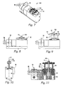
- fork-shaped support 125 and/or frame 111 is moved to align that die with pick head device 150, which is shown in Figs. 2 and 3, and shown in detail in Figs. 7-11.
- pick head 150 is facing up, revealing interchangeable rubber tip 51 which has a suction port 152 which operates to hold a die against tip 51 when a suction is present inside tip 51.
- Tip 51 is interchangeable to permit pick head 150 to operate with different sized die, thus the size of port 152 varies with the size and shape of the die to be handled.
- pick head tip 51 is mounted on pick plate 53 which extends as seen in Figs.
- pick plate 53 is effectuated via two pneumatic control lines 37 (see Fig. 2) which feed to two pneumatic ports 59 and which feed to cylinder 58 on either side of piston 59.
- air pressure is applied to either side of piston 59, plate 53, which rides on guide rods 56, extends and retracts as required.
- Suction at port 152 is supplied via a third control line 37, and is supplied axially through cylinder 58 and piston 59.
- Hole 55 (Figs. 11 and 12d) is normally covered during operation, but provides an alignment utility to align pick head 140 with pins of strip head 130.
- Strip head 130 rotates on an axis parallel with the plane of wafer 105 and perpendicular with the direction of travel of conveyor 170.
- Strip head 130 is shown in a non-rotated position in Fig. 13a and a rotated position in Fig. 13b.
- the head may be pneumatically actuated or electro-mechanically actuated for rotation so that wafer ring 110, shown in Fig. 38, which is significantly thicker than wafer 105, can pass by the non-rotated strip head 130 during insertion and ejection of the wafer and during vision imaging of wafer 105 at the extreme right side of wafer 105 as seen in Figs. 2 and 3.
- Guyway 129 provides a means for maintaining control lines within the narrow profile of the invention by passing the control lines over the strip head assembly 128.
- Dies are removed from wafer 105 in a manner typical in the industry.
- a vacuum is applied by strip head 130 to the flexible film to stabilize it.
- a pin or pins 134 push through the flexible film from the rear side, i.e., from within strip head 130, while at the same time, pick head 150 applies a vacuum to the die itself on the front of the wafer.
- the number and configuration of pins 134 varies with the size and shape of the die.
- Strip head 130 is removable, and can be replaced with a different sized strip head, such as the smaller one shown in Figs. 14-17a, and/or having a different pin configuration depending upon the size of the die to be extracted.
- Two pneumatic control lines 157 are provided to strip head 130.
- One of pneumatic control lines 137 provides a vacuum which is applied to the flexible film to stabilize it.
- the second of pneumatic control lines 137 operates a piston within strip head 130 which in turn operates pin or pins 134.
- the rotation of strip head 130 may be operated by electro-mechanical rotating actuator 132 (see Fig. 2), which operates in response to a signal 135 from control unit 101, but other motivating means can be used instead.
- pneumatic control is implemented to rotate strip head 130.
- Pins 134 are actuated pneumatically in response to air vacuum or pressure transmitted via one of control lines 137 from the pneumatic control assembly 106, which is in turn controlled via lines 135 from control unit 101.
- pins 134 are actuated pneumatically in the preferred embodiment, any other type of actuator suitable for the purpose can also be used.
- Figs. 14 and 16 show a bottom view of strip arm 25 with strip head in rotated and non-rotated positions respectively.
- Figs. 15 and 17 are sectional views of Figs. 14 and 16 and attempt to show the altered position of rack assemblies 32, shown in detail views 15a and 17a, which respond to pistons which arc provided with pressurized air or vacuum, depending on the desired movement.
- Rack assemblies 32 extend in response to increased air pressure present in respective cylinders, causing pinion gears (not shown) connected to strip head 130 to rotate.
- spud 35 extends, engaging a flat surface on strip head 130, thereby preventing unwanted rotation, which is particularly required when auto-loading or auto-ejecting a wafer, which operation is discussed in further detail in the next paragraph.
- strip head 130 serves another important function, which is to partially automate the insertion and ejection of the wafer.
- wafer entry and control doors 82 are shown in the open position.
- the control doors 82 have guides in the form of grooves 84 which ensure that the wafer is properly aligned to the opening during insertion and removal, minimizing the potential for damage to the wafer.
- doors 82 are closed.
- Control unit 101 senses the position of control doors 82 via door sensor 86.
- Fork-shaped support 125 shown in Figs. 2-4, slides horizontally until strip head 130 is inside ring 110.
- Strip head 130 then rotates to the rotated position shown in Fig. 6b and slides (with fork 125) in the positive x direction, towards pickup location 173, until the side of strip head 130 engages the inside edge of ring 110.
- Strip head 130 then continues to the positive x direction, dragging ring 110 with it until it taches the fully mounted position shown in Fig. 2.
- the strip head 130 performs the same operation in reverse, pushing ring 110 out from outside ring 110, until it can be manually pulled out the rest of the way through doors 82.
- the invention allows a single wafer to be inserted into the feeder multiple times for short run production, or simply exhausted in a volume environment.
- Pick head 150 includes a suction port 152, seen in Figs. 7-11 and 12c. and die strip head 130 includes a pin structure 134.
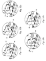
- the pick head 150 rotates to face the die as shown in Figs. 5 and 12a and pick head plate 53 extends toward the selected die to place suction port 152 in contact with the selected die. Then the suction port 152 of pick head 150 activates to hold the die against suction port 152 once it is released from the adhesive material.
- the strip head 130 in the rotated position shown in Fig. 13b, applies suction to the flexible adhesive film that the wafer is mounted on to stabilize the film using suction ports 132.
- pins 134 extend from one or more of suction ports 132, through the flexible film to which the selected die is mounted, forcing the selected die from the material and against suction port 152 where it is held by the applied suction.
- the number of pins utilized and their configuration depends in part on the size of the die to be extracted as is known in the art. Pins 134 then retract and pick head plate 53 retracts, separating the die from the wafer. Due to perforations caused by pins 134 in the film, a strong vacuum is necessary to maintain the film against strip head 130 when removing a die which is adjacent to a recently removed die.
- Flag 54 shown in Figs. 7-11, is a simple extension to provide an indication to a feedback sensor (not shown) for confirmation of rotation actuation of pick head 59.
- Disposition of the picked die by the pick head depends on whether the die is required to be placed in a circuit up orientation or a "flipped" or circuit down orientation. If the die is required to be placed circuit-up then the pick head 150 rotates 90° down as seen in Fig. 12b, Pick head plate 53 then extends to place the die on conveyor 170 as seen in Fig. 12e, then the die is released by removing suction from port 152 and supplying a puff, or a series of puffs, of air to blow the die off port 152, and finally the pick head plate 53 retracts once more and rotates to face the wafer in preparation to pick the next die.
- the selected die is always adjacent to conveyor 170 and pick head 150 requires only minimal movement to extract the die from the wafer and place it on the conveyor. Furthermore, since the pick head moves in the x or negative x direction, it can place multiple die on the conveyor without any requirement that the conveyor advance. This permits asynchronous operation between the pick head and the conveyor, and allows the conveyor to operate as a buffer between the pick head operation and the assembly machine retrieving die from the conveyor at pickup location 176.
- the pick head 150 rotates 90° up as shown in Fig. 12c and pick head plate 153 extends upward to place the die in contact with flip head 140 which also has a suction port that is activated when pneumatic control assembly 106 applies a suction to pneumatic control line 187.
- suction port of flip head 140 is activated, suction from port 152 of pick head 150 is removed, thus transferring the die from pick head 150 to flip head 140.
- Pick head plate 153 then retracts and pick head 150 rotates to face the wafer, ready for the next selected die.
- Linear actuator 159 which may be an electro-mechanical actuator or a pneumatic actuator, operates to shift support 155 to the left in response to signal 157 from control unit 101.
- Camera 160, its associated mirror 162 and light source 164, as well as flip head 140 are mounted to support 155 and so they all shift to the left.
- Flip head 140 then drops to place the die in contact with conveyor 170 as shown in Fig. 12d.
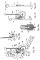
- flip head 140 is mounted to an elongated tube 141 formed of light-weight titanium having a flat, hardened wear plate 147 along its mid-section.
- the head and tube assembly shown in Fig. 20 is ultra-light weight to reduce inertial forces.
- Tube 141 is positioned between four roller-bearings 183 and friction drive roller 182 (see fig. 18a) attached to pulley 186.
- stepper motor 188 which is mounted to shift support 155, activates pulley 186 via belt 187.
- Pulley 186 is connected to friction drive roller 182 which is spring-biased against wear plate 147. Spring biasing is effectuated through mounting drive arm 181 on pivot 184 and biasing mounting drive arm 181 against bear plate 147.
- Tensioning arm 189 is similarly biased against belt 187 to provide tension to belt 187 through tensioning pulley 185.
- Tube 141 When pulley 186 is rotated, the friction drive roller rolls against wear plate 147, causing entire tube 141 to raise or lower.
- suction port 144 At the top of tube 14 is suction port 144 for supplying suction to flip head 140.
- Flip head 140 also has a rubber tip 142 at its bottom end which includes a suction port for holding onto a die when its transferred from pick head 150 until it is placed onto conveyor belt 170 and released.
- Tube 141 also includes a sensor flag 146 for providing feedback to control unit 101 in case of malfunction.
- Flip head 140 includes a cylindrical chamber in which piston 143 having several holes drilled through it around the periphery thereof. Piston 143 also includes a push-off pin 149 extending from its bottom and out through tip 142. During periods of negative pressure, i.e., when holding a die, piston 143 lifts up allowing air to rush in through tip 142 and through holes in piston 143. When a die is being released, a puff of air blows down, causing piston 143 to drop and thereby pushing a die off tip 142 with push-off pin 149.
- Fig. 21 shows the shifting mechanism from substantially the same perspective as generally seen in Fig. 3. while Fig. 22 shows the same apparatus from a reverse perspective.
- Shift support 155 moves axially with respect to pick arm support 126.
- Stepper motor 259 is mounted to shift support 155 while rack gear 254 is mounted to and remains stationary with pick arm support 126.
- rack gear 254 is mounted to and remains stationary with pick arm support 126.
- pinion gear 253 extending from motor 259 is engaged with rack gear 254 such that when motor 259 receives signals via line 157 from control unit 101, pinion gear 253 rotates, causing shift support 155 to move relative to pick arm support 126.
- Sensor 257 detects presence of sensor flag 256 in known manner providing feedback to control unit 101.
- conveyor 170 may be activated to transport the die to pickup location 176 where stop 174 prevents the die from traveling too far and helps to precisely position the die for pickup.
- wafer frame 111 and/or fork-shaped support 125 move into position for the next selected die to be removed.
- die are removed from the wafer in a right to left, then bottom to top pattern.
- the control unit 101 must determine during the processing of a row of die whether the next pick process or vision process should be done first or if both can be done from the same location. Initially, this means that only the vision process will be running for several die, until pick head 150 is also over the wafer. Near the end of the row camera 160 will run off the left end of the wafer but there still may be die in that row for pick head 150 to pick.
- pick head 150 moves back to the right most die in the current row and frame 111 lowers one die interval to the start location of the next row.
- Conveyor belt 170 will now be described with reference to Figs. 7-10.
- Motor 177 drives conveyor belt 170 in response to commands from control unit 101.
- Motor 177 drives pinion gear 74 which drives intermediate gear 73, which in turn drives drive gear 72, which is attached to drive pulley 28 1 (see Fig. 27).
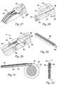
- Conveyor belt 170 includes steel belt 270, preferably comprising a stainless steel and is advantageously a high yield 300 series stainless steel approximately 4 thousandths of an inch thick (1.0 ⁇ m).
- Belt 170 is tensioned via tensioning device 179 (Fig. 3). To dampen or prevent vibrations, the belt rides on and is magnetically coupled to a "hard deck” surface discussed in further detail below.
- a low friction coating 27 such as an ultra high molecular weight polyethylene material is coated or applied with a pressure-sensitive adhesive to steel belt 270 to reduce friction between belt 170 and decking 283 (to be discussed in further detail below with reference to Figs. 27-32).
- the combined thickness of polyethylene and adhesive is approximately 0.0065 inches (1.7 ⁇ m).
- Low friction coatings 272 and 273, on either side on top of steel belt 270 are identical to low friction coating 271 and have the purpose of reducing wear and friction as belt passes reversing structures 172 (see Fig. 3) and pinch points 171 (see Figs. 3 and 29).
- steel belt 270 is provided with an elastomer coating 276 on its top surface to further reduce any migration of die.
- Elastomer coating 276 is a polyurethane with an elastomer compound to increase the friction between the die and the belt, and preferably has a hardness of Cast-70 Shore A. As with low friction coating 271, elastomer coating 276 is applied to steel belt 270 using a pressure-sensitive adhesive.
- elastomer coating 276 can create too much adhesion between die and conveyor, causing a die to "stick" to the belt rather than being properly picked up by the host machine.
- grooves 277 (shown in Fig. 24) are ground into the coating to reduce adhesion.
- Figure 24 shows a die example 278 which is on the order of 1mm wide.
- Die example 278 is a flip chip and includes solder bumps 279 which interface with grooves 277, which further reduces die migration. Grooves 277 will inhibit die migration of flip chips in this manner whether or not solder bumps mesh perfectly with them.
- Guide bumps 274 are attached in two continuous rows along the bottom of steel belt 270.
- Guide bumps 274 arc formed by turning, i.e., machining, or stamping them from a low-friction plastic.
- guide bumps 274 are formed from acetal resin, such as that sold under the trade name Delrin by DuPont White (virgin) Delrin is most preferably employed.
- Guide bumps 274 are generally doughnut-shaped and have a inner circumference that is somewhat smaller at its center than at either the top or bottom. This shape allows the guide bumps 274 to form a mechanical connection with glue 275 which holds guide bumps to steel belt 270 (see Fig. 26).
- Glue 275 is a dual-mode UV-activated acrylic based adhesive having good elastic properties and is thicksotropic, i.e., thick when applied. Glue No. 911, sold by Dymax Corp. of Torrington, CT, has been found satisfactory for this purpose. Longitudinal spacing of guide bumps 274 is not critical, though precise transverse positioning of guide bumps 274 is crucial. As is discussed in more detail below, guide bumps 274 play a key role in ensuring consistent positioning of die for ready retrieval by the host machine.
- Deck 280 includes guide wheel 284 at the rear end of deck 280 and guide wheel 288 at its front end.
- Guide wheels 284 and 288 maintain a very small clearance, on the order of 0.001" (.025mm), within a central circumferential groove 290 in both front and rear pulleys 79 and 71, respectively.
- These guide wheels serve to position deck 280 thereby steering the belt into an accurate position on the pulleys, preventing any drift of the belt resulting from its natural camber.
- the width of channels 285 is narrowed, forming a choke 288 such as that shown in Fig. 29.
- these choke points are positioned at either end of drop zone 173 where die may be placed on conveyor 170, and at the pick point 176.
- channels 75 narrow, precisely locating guide bumps 184 along the z-axis thereby precisely locating belt 170.
- Clamp 287 shown in Figs. 3 and 29, hold down conveyor belt 170 at one of chokes 288 to prevent guide bumps 274 from popping out channels 285.
- Low friction coatings 272 and 273 formed on steel belt 270 reduce friction between clamp 287 and conveyor belt 170.
- decking includes a rubber magnet 286 covered with a low-friction decking material 283 which is preferably acetal resin (DELRIN) and which is laminated, e.g., using pressure-sensitive adhesive onto rubber magnet 286.
- Rubber magnet 286 is best viewed in Figures 28 and 31 and serves the function of magnetically coupling belt 170 to deck 280, thereby preventing and dampening vibrations of belt 170 which may occur perpendicularly to the plane of the belt.
- ramp section 172 of belt 170 serves the purpose of elevating die from a first height at the drop region 173 to a second height at pickup location 176.
- the ramp 172 is a necessary and important innovation in the development of a direct die feeder because it permits fork-shaped support 125 to slide back and forth in the direction of the x-axis without extending into a region of space above the conveyor to which the host machine must have access.
- drop region 173 would be at the same elevation as pickup location 176, which would necessitate raising fork-shaped support 125 into a fly-zone of the host machine, and the pick and place head of the host machine would inevitably crash into fork-shaped support 125.
- Belt reversing structures 171 hold conveyor belt 170 down against deck 70 and provide a gentle turn as conveyor belt 170 changes direction from a flat area including drop zone 173 to ramp section 172.
- Low friction coatings 272 and 273 seen in Figs. 8 and 9 reduce friction of conveyor belt 170 as it passes against belt reversing structures 171.
- Control unit 101 keeps track of the position of each die on conveyor belt 170 and, depending on the mode of operation, it may be programmed to advance as each die is removed from the pickup location except during the placing operation by pick head 150 or flip head 140.
- a sensor 176 (see Fig. 2) comprising two photo-emitter optical fiber bundles 198.
- Sensor 176 includes a light source and a photo sensor (not show) each having one of optical fiber bundles 198 extending to stop 174 shown in Figs. 3 but shown in detail in Fig. 36.
- Optical fiber bundles 198 extend through openings in stop and fiber bundle support 196 and extend to positions on either side of stop surface 197.
- the fiber bundles are ground down to form a refracting surface as is known in the art to bend light so that it passes across stop surface 197.
- a die is present at pickup location 176 against stop surface 197, light from one fiber bundle to the other is blocked.
- control unit 101 over-travels the conveyor belt 170 slightly so as to square the die against stop surface 197 and to knock the die loose from the friction-enhancing polymer surface 276 in case it has become stuck to said surface.
- Belt cleaning device 190 will now be described with reference to Figs. 1, 2, and 17-19. There will inevitably be some silicon particles or other material particles which come in contact with the belt 171 and perhaps stick in place. Additionally, dust is a concern, particularly when supplying chips in a flipped, or circuit-down, orientation since dust and other particles can affect the mechanical and electrical connections between die and substrate after the die is delivered to the host machine.
- a belt cleaner 190 is employed. Belt cleaner 190 includes four nylon brushes 191 mounted adjacent and below the returning portion of conveyor belt 170. Brushes 191 are made from 0.25 inch (6.4 mm) nylon bottle brushes mounted to a twisted wire.
- Belt cleaner 190 is mounted to posts 195 which have a detent in them which is engaged by a spring-biased ball bearing 194 so that the cleaner snaps onto posts 195. It is easily removed for servicing (e.g., cleaning) by grasping handle 193 and sliding it off posts 195. Additionally, belt cleaner 190 includes a high-strength neodymium magnet 193 to pull the belt into contact with brushes 191 and remove magnetic contamination from belt 170, such as magnetic particles.
Landscapes
- Container, Conveyance, Adherence, Positioning, Of Wafer (AREA)
Claims (16)
- Dispositif d'alimentation en puces (100) permettant d'alimenter une machine de placement automatisée hôte, en série, en un ensemble de composants (105) attachés à un film flexible, le dispositif d'alimentation en puces comprenant :un support (110) permettant de supporter le film flexible selon une configuration plane et sensiblement verticale;une zone de dépose (173) ;un emplacement de ramassage de composants (176) auquel peut accéder une machine de placement automatisée hôte ;un transporteur de composant (170) s'étendant sensiblement horizontalement entre ladite zone de dépose (173) et ledit emplacement de ramassage de composant (176) ;une tête de ramassage (150), ladite tête de ramassage pouvant retirer un composant sélectionné dudit ensemble de composants (105) placés sur ledit film flexible et placer ledit composant sélectionné sur ledit transporteur de composant (170) au niveau de la zone de dépose (173) ; etune unité de commande (101) permettant de commander le transporteur de composant (170) et commander la tête de ramassage (150) afin de transporter simultanément une pluralité de composants (205) vers l'emplacement de ramassage de composant (176) et permettre un fonctionnement asynchrone entre la tête de ramassage et le transporteur.
- Dispositif d'alimentation en puces (100) selon la revendication 1, dans lequel ledit ensemble de composants (106) est agencé selon un motif bidimensionnel sur ledit film flexible et dans lequel ledit dispositif d'alimentation comprend en outre un moyen permettant de déplacer au moins l'un desdits têtes de ramassage (150) et film flexible de telle sorte que ladite tête de ramassage peut accéder à tous les composants dudit ensemble de composants (105).
- Dispositif d'alimentation en puces (100) selon la revendication 2, dans lequel une région adjacente audit ensemble de composants est divisée par le plan du film flexible en un premier côté et un deuxième côté de telle sorte que le premier côté comporte ledit ensemble de composants et s'étend à distance de la surface sur laquelle ledit ensemble de composants est attaché au film flexible et le deuxième côté se trouve sur le côté opposé du film flexible et s'étend à distance dudit premier côté, dans lequel ladite tête de ramassage est située sur ledit premier côté dudit ensemble de composants, ledit dispositif d'alimentation en puces comprenant en outre :une tête de déchargement (130), située sur le deuxième côté à distance dudit ensemble de composants, ladite tête de déchargement maintenant une position correspondant à ladite tête de ramassage (150) de telle sorte qu'une ligne imaginaire s'étendant à partir de ladite tête de déchargement jusqu'à ladite tête de ramassage est sensiblement perpendiculaire à ladite surface du film flexible, ladite tête de déchargement comportant une structure à tige comprenant au moins une tige (134) manoeuvrable pour s'étendre à partir de ladite tête de déchargement vers ledit composant sélectionné pour libérer ledit composant sélectionné dudit film flexible et faire passer ledit composant sélectionné vers ladite tête de ramassage ; etdans lequel ladite tête de ramassage comporte un port d'aspiration (152) permettant de maintenir ladite puce sélectionnée contre ledit port d'aspiration en appliquant un vide sur ledit port d'aspiration.
- Dispositif d'alimentation en puces (100) selon la revendication 3, comprenant une tête de retournement (140), dans lequel ladite tête de ramassage est adaptée pour retirer le composant sélectionné du film flexible et de placer le composant sélectionné sur ledit transporteur de composant (170) selon une orientation classique et est adaptée également pour faire passer le composant sélectionné retiré du film flexible vers ladite tête de retournement, ladite tête de retournement permettant de prendre le composant sélectionné à ladite tête de ramassage puis de placer le composant sélectionné sur ledit transporteur de composant selon une orientation retournée.
- Dispositif d'alimentation en puces (100) selon la revendication 3 ou 4, dans lequel ladite tête de déchargement (130) est adaptée pour éjecter ledit composant sélectionné dudit film flexible en stabilisant d'abord une région dudit film flexible entourant ledit composant sélectionné puis en éjectant ledit composant sélectionné.
- Dispositif d'alimentation en puces (100) selon la revendication 3, 4 ou 5, comprenant une structure support en forme de fourche (125) ayant un premier bras adapté à supporter ladite tête de ramassage (150) dudit premier côté dudit ensemble de composants et un deuxième bras pour supporter ladite tête de déchargement dudit côté dudit ensemble de composants, ladite structure en forme de fourche conservant l'alignement entre ladite tête de ramassage et ladite tête de déchargement.
- Dispositif d'alimentation en puces (100) selon la revendication 6, dans lequel ledit support en forme de fourche (125) est monté libre en translation uniquement sur un axe horizontal qui est parallèle auxdits premier et deuxième côtés et est sensiblement horizontal et ledit support de composant est monté libre en translation uniquement sur un axe vertical, qui est parallèle auxdits premier et deuxième côtés et perpendiculaire audit axe horizontal, ledit dispositif d'alimentation en puces comprenant en outre :un premier stimulateur de positionnement automatique (101, 122) permettant de positionner ledit support de fourche (125) le long dudit axe horizontal ;un deuxième stimulateur de positionnement automatique (101, 112) permettant de positionner ledit film flexible le long dudit axe vertical ;un stimulateur de transporteur (177) permettant de faire fonctionner ledit transporteur (170) vers l'avant et vers l'arrière ; etun système de vision artificielle ayant une caméra (160) montée sur ledit premier bras dudit support en forme de fourche afin de localiser et inspecter avec précision ledit composant sélectionné.
- Dispositif d'alimentation en puces (100) selon l'une quelconque des revendications précédentes, comprenant un cadre (111) permettant de supporter ledit film flexible, ledit cadre définissant la taille limite dudit film flexible et ledit transporteur de composants (170) comprend en outre un pont (283) disposé entre deux poulies, ledit transporteur de composant coulissant contre ledit pont et étant maintenu en tension par lesdites deux poulies, ledit transporteur de composant s'étend sensiblement le long et parallèlement audit premier plan et comporte une région de dépose (173) s'étalant sur la largeur dudit cadre et s'étendant dans un sens au-delà de ladite région de dépose jusqu'à un emplacement de ramassage qui se trouve à l'extérieur de ladite région de dépose.
- Dispositif d'alimentation en puces (100) selon l'une quelconque des revendications précédentes, comprenant un dispositif de nettoyage (190) comprenant au moins une brosse (191) disposée de manière adjacente à une partie de retour dudit transporteur de composants (170), ledit dispositif de nettoyage comportant en outre un aimant (193) permettant de maintenir ledit transporteur de composants contre ladite au moins une brosse et faciliter le retrait de toute particule métallique et magnétique présente sur ledit transporteur de composants.
- Procédé permettant de retirer un composant d'un film flexible et de transporter ledit composant jusqu'à un emplacement du ramassage (176) à l'aide d'un dispositif d'alimentation en puces (100), comprenant les étapes consistant à :extraire ledit composant dudit film flexible à l'aide d'une tête de ramassage (150) ;placer ledit composant sur un transporteur (170) au niveau d'une zone de dépose (173) adjacente audit film flexible ; etfaire fonctionner ledit transporteur et ladite tête de ramassage de manière asynchrone afin de transporter simultanément une pluralité de puces vers un emplacement de ramassage (176) en vue d'un retrait subséquent des composants par un système d'assemblage en vue de leur installation sur une carte de circuits imprimés.
- Procédé selon la revendication 10, ladite étape d'extraction comprenant les étapes consistant à :localiser l'emplacement précis desdits composants à l'aide de la machine de vision (180) ;positionner une tête de ramassage (150) au-dessus dudit composant ; etretirer ledit composant dudit film flexible.
- Procédé selon la revendication 10 ou 11, dans lequel ladite étape de faire fonctionner ledit transporteur (170) comporte l'étape consistant à arrêter ledit transporteur lorsque soit un composant est placé sur ledit transporteur soit une puce est présente au niveau dudit emplacement de ramassage (176).
- Procédé selon la revendication 12, dans lequel ledit transporteur (170) comporte une butée au niveau de l'emplacement de ramassage (176) et ledit procédé permettant de faire fonctionner ledit transporteur comprend en outre l'étape consistant à faire fonctionner ledit transporteur pour qu'il fasse un trajet de dépassement lorsque ledit composant atteint ladite butée (197) afin de mettre ledit composant à l'équerre contre ladite butée et de relâcher ledit composant à partir d'une surface dudit transporteur.
- Procédé de retrait de composants d'un film flexible et de présentation desdits composants dans une orientation classique ou une orientation retournée, en utilisant un appareil selon la revendication 4, comprenant les étapes consistant à :extraire un composant dudit film flexible à l'aide d'une tête de ramassage (150) ;placer ledit composant avec ladite tête de ramassage (150) directement sur un transporteur (170) si ledit composant doit être présenté en vue d'un retrait dans une orientation classique ;faire passer ledit composant vers une tête de retournement (140) puis placer le composant directement sur le transporteur si le composant doit être présenté en vue d'un retrait dans une orientation retournée ; etfaire fonctionner ledit transporteur afin de transporter ledit composant jusqu'à un emplacement de ramassage (176).
- Procédé selon la revendication 14, dans lequel ladite étape d'extraction d'un composant dudit film flexible et ladite étape de placement dudit composant sur le transporteur (170) à l'aide d'une tête de retournement (140) sont exécutées concurremment lorsque ledit composant doit être présenté dans une orientation retournée.
- Procédé de présentation de composants à une machine d'assemblage utilisant un dispositif d'alimentation en puces, comprenant les étapes suivantes exécutées dans l'ordre donné :supporter un film flexible dans une orientation sensiblement verticale ;fournir une tête de ramassage (150) ;utiliser ladite tête de ramassage pour retirer de manière répétitive lesdits composants du film flexible ;déposer les composants retirés sur un transporteur de composant (170) au niveau d'une zone de dépose (173) adjacente audit film flexible, ledit transporteur de composant se déplaçant entre la zone de dépose (173) où les composants ont été déposés par ladite tête de ramassage et un deuxième emplacement auquel peut accéder une machine d'assemblage ; etfaire fonctionner ledit transporteur et ladite tête de ramassage de manière asynchrone pour transporter simultanément une pluralité de puces vers un emplacement de ramassage (176) en vue du retrait subséquent des composants par une machine d'assemblage pour qu'elles soient installées sur une carte de circuit imprimé.
Applications Claiming Priority (3)
| Application Number | Priority Date | Filing Date | Title |
|---|---|---|---|
| US09/025,564 US5976306A (en) | 1998-02-18 | 1998-02-18 | Method and apparatus for removing die from an expanded wafer and conveying die to a pickup location |
| PCT/US1999/003385 WO1999042289A1 (fr) | 1998-02-18 | 1999-02-17 | Procede et appareil d'extraction d'une puce d'une tranche et de transport de ladite puce jusqu'a un point de collecte |
| US25564 | 2001-12-18 |
Publications (3)
| Publication Number | Publication Date |
|---|---|
| EP1064152A1 EP1064152A1 (fr) | 2001-01-03 |
| EP1064152A4 EP1064152A4 (fr) | 2005-10-05 |
| EP1064152B1 true EP1064152B1 (fr) | 2008-01-09 |
Family
ID=21826796
Family Applications (1)
| Application Number | Title | Priority Date | Filing Date |
|---|---|---|---|
| EP99908205A Expired - Lifetime EP1064152B1 (fr) | 1998-02-18 | 1999-02-17 | Procede et appareil d'extraction d'une puce d'une tranche et de transport de ladite puce jusqu'a un point de collecte |
Country Status (6)
| Country | Link |
|---|---|
| US (1) | US5976306A (fr) |
| EP (1) | EP1064152B1 (fr) |
| JP (1) | JP4781529B2 (fr) |
| AU (1) | AU2769699A (fr) |
| DE (1) | DE69937949T2 (fr) |
| WO (1) | WO1999042289A1 (fr) |
Families Citing this family (28)
| Publication number | Priority date | Publication date | Assignee | Title |
|---|---|---|---|---|
| US6157870A (en) * | 1997-02-18 | 2000-12-05 | Zevatech Trading Ag | Apparatus supplying components to a placement machine with splice sensor |
| DE59711263D1 (de) | 1997-10-30 | 2004-03-04 | Esec Trading Sa | Verfahren und Einrichtung für die Justierung des Bondkopfs einer Maschine für das Bonden von Halbleiterchips auf ein Trägermaterial |
| US6173750B1 (en) * | 1998-02-18 | 2001-01-16 | Hover-Davis, Inc. | Method and apparatus for removing die from a wafer and conveying die to a pickup location |
| US6122561A (en) * | 1998-09-01 | 2000-09-19 | Ciena Corporation | Precision continuous surface guided optical module carrier and method of using same |
| US6554128B1 (en) | 1999-10-07 | 2003-04-29 | Delaware Capital Formation, Inc. | Die shuttle conveyor and nest therefor |
| US20020003994A1 (en) * | 2000-07-07 | 2002-01-10 | Peter Davis | Component source interchange gantry |
| US6773543B2 (en) * | 2002-05-07 | 2004-08-10 | Delaware Capital Formation, Inc. | Method and apparatus for the multiplexed acquisition of a bare die from a wafer |
| US7023347B2 (en) * | 2002-08-02 | 2006-04-04 | Symbol Technologies, Inc. | Method and system for forming a die frame and for transferring dies therewith |
| US7306695B2 (en) * | 2003-04-10 | 2007-12-11 | Matsushita Electric Industrial Co., Ltd. | Apparatus and method for picking up semiconductor chip |
| US7404199B2 (en) * | 2003-06-12 | 2008-07-22 | Symbol Technologies, Inc. | Method, system, and apparatus for high volume assembly of compact discs and digital video discs incorporating radio frequency identification tag technology |
| JP2005045023A (ja) * | 2003-07-22 | 2005-02-17 | Toshiba Corp | 半導体装置の製造方法および半導体製造装置 |
| US7207430B2 (en) * | 2004-10-25 | 2007-04-24 | Ui Holding Company | Vacuum gripper for handling small components |
| NL1029207C2 (nl) * | 2005-06-07 | 2006-12-08 | Assembleon Nv | Componentpositioneringsinrichting alsmede een werkwijze voor het positioneren van een component. |
| DE102005061680B3 (de) * | 2005-12-21 | 2007-09-13 | Mühlbauer Ag | Einrichtung und Verfahren zur gleichzeitigen Übertragung einer Mehrzahl von elektronischen Bauteilen |
| JP2007297167A (ja) * | 2006-04-28 | 2007-11-15 | Toyota Motor Corp | マグネットコンベア |
| DE102007048410B4 (de) | 2007-10-09 | 2009-07-30 | Siemens Ag | Zuführvorrichtung für Bauelemente zu einem Bestückautomaten zur Bestückung von Substraten mit den Bauelementen |
| DE102007048413B3 (de) * | 2007-10-09 | 2009-04-16 | Siemens Ag | Zuführvorrichtung vor Bauelemente zu einem Bestückautomaten zur Bestückung von Substraten mit Bauelementen |
| US7819239B2 (en) * | 2008-12-11 | 2010-10-26 | Schenson Co., Ltd. | Feeder for an auto mounting device |
| US20110182701A1 (en) * | 2010-01-28 | 2011-07-28 | Ui Holding Co. | Method and apparatus for transferring die from a wafer |
| CN105704998B (zh) * | 2014-11-27 | 2019-02-22 | 英业达科技有限公司 | 取件置放方法 |
| CN104701227B (zh) * | 2015-03-27 | 2017-12-29 | 江苏艾科瑞思封装自动化设备有限公司 | 用于集成电路封装设备的料片进给机构 |
| JP7090066B2 (ja) * | 2016-07-13 | 2022-06-23 | ユニバーサル インスツルメンツ コーポレーション | モジュール式ダイ取扱いシステム |
| US10529600B2 (en) * | 2017-03-30 | 2020-01-07 | Intel Corporation | Decoupling systems |
| CN109712917B (zh) * | 2018-12-29 | 2024-06-04 | 苏州矽微电子科技有限公司 | 一种wafer扩晶转移贴膜方法及其机构 |
| CN111276435B (zh) * | 2020-03-19 | 2022-04-15 | 中国科学院苏州生物医学工程技术研究所 | 宽范围、均匀应变的柔性电子基底近圆式拉伸系统 |
| TWI800211B (zh) * | 2021-11-05 | 2023-04-21 | 斯託克精密科技股份有限公司 | 用於將電子元件自撓性承載基板移轉至撓性目標基板之裝置以及轉移電子元件之方法 |
| CN116092971B (zh) | 2021-11-05 | 2026-04-17 | 麦科先进股份有限公司 | 用于将电子组件自挠性承载基板移转至挠性目标基板的装置以及转移电子组件的方法 |
| CN116730005B (zh) * | 2023-07-10 | 2024-01-23 | 芯朋半导体科技(如东)有限公司 | 一种矩阵式巨量检测机构 |
Family Cites Families (16)
| Publication number | Priority date | Publication date | Assignee | Title |
|---|---|---|---|---|
| US2241640A (en) * | 1938-12-08 | 1941-05-13 | Libbey Owens Ford Glass Co | Conveyer |
| JPS5599795A (en) * | 1979-01-25 | 1980-07-30 | Matsushita Electric Industrial Co Ltd | Device for mounting electronic part |
| SE8500193L (sv) * | 1984-01-19 | 1985-07-20 | Recycloplast Ag | Forfarande for att blanda hellbara material med ett instellbart blandningsforhallande som en del av ett forfarande for att bearbeta materialen jemte anordning for att utfora forfarandet |
| US4876791A (en) * | 1986-04-22 | 1989-10-31 | Kulicke & Soffa Industries, Inc. | Apparatus for and methods of die bonding |
| IT1201888B (it) * | 1986-07-29 | 1989-02-02 | Dario Toncelli | Nastro trasportatore con risalti inclinati in sensi opposti |
| JP3228959B2 (ja) * | 1991-07-18 | 2001-11-12 | ローム株式会社 | ペレットのピックアップ装置 |
| US5161666A (en) * | 1991-08-26 | 1992-11-10 | Hugh D. Eller | Conveyor belt cleaner |
| JP2563550Y2 (ja) * | 1991-10-31 | 1998-02-25 | スズキ株式会社 | ベルトコンベア |
| JP2536371B2 (ja) * | 1992-09-10 | 1996-09-18 | 東芝精機株式会社 | 半導体ペレットボンディング方法 |
| JPH0697214A (ja) * | 1992-09-14 | 1994-04-08 | Hitachi Ltd | ピックアップ装置 |
| JPH06338556A (ja) * | 1993-05-28 | 1994-12-06 | Naito Densei Kogyo Kk | 細長ペレットの抽出装置 |
| JPH081925B2 (ja) * | 1993-10-29 | 1996-01-10 | 東芝精機株式会社 | ペレット突き上げ装置 |
| JPH0837223A (ja) * | 1994-07-25 | 1996-02-06 | Rohm Co Ltd | 半導体チップのピックアップ装置 |
| JPH08124994A (ja) * | 1994-10-19 | 1996-05-17 | Hitachi Ltd | ペレット分類装置 |
| US5671530A (en) * | 1995-10-30 | 1997-09-30 | Delco Electronics Corporation | Flip-chip mounting assembly and method with vertical wafer feeder |
| DE59603376D1 (de) * | 1996-02-29 | 1999-11-18 | Alphasem Ag Berg | Verfahren und vorrichtung zum aufnehmen, orientieren und montieren von bauelementen |
-
1998
- 1998-02-18 US US09/025,564 patent/US5976306A/en not_active Expired - Lifetime
-
1999
- 1999-02-17 JP JP2000532273A patent/JP4781529B2/ja not_active Expired - Fee Related
- 1999-02-17 WO PCT/US1999/003385 patent/WO1999042289A1/fr not_active Ceased
- 1999-02-17 EP EP99908205A patent/EP1064152B1/fr not_active Expired - Lifetime
- 1999-02-17 DE DE69937949T patent/DE69937949T2/de not_active Expired - Lifetime
- 1999-02-18 AU AU27696/99A patent/AU2769699A/en not_active Abandoned
Also Published As
| Publication number | Publication date |
|---|---|
| AU2769699A (en) | 1999-09-06 |
| DE69937949T2 (de) | 2008-12-24 |
| EP1064152A1 (fr) | 2001-01-03 |
| DE69937949D1 (de) | 2008-02-21 |
| JP2002503891A (ja) | 2002-02-05 |
| US5976306A (en) | 1999-11-02 |
| JP4781529B2 (ja) | 2011-09-28 |
| WO1999042289A1 (fr) | 1999-08-26 |
| EP1064152A4 (fr) | 2005-10-05 |
Similar Documents
| Publication | Publication Date | Title |
|---|---|---|
| US6173750B1 (en) | Method and apparatus for removing die from a wafer and conveying die to a pickup location | |
| EP1064152A1 (fr) | Procede et appareil d'extraction d'une puce d'une tranche et de transport de ladite puce jusqu'a un point de collecte | |
| KR100205537B1 (ko) | 칩의 탑재장치 및 탑재방법 | |
| US4881319A (en) | Process for mounting chip type circuit elements on printed circuit boards and apparatus therefor | |
| US4624050A (en) | Head for handling electrical components | |
| EP1620889B1 (fr) | Procede et appareil permettant l'acquisition multiplexee d'une puce nue a partir d'une plaquette | |
| JPS63202098A (ja) | 部品供給手段 | |
| CN113314445B (zh) | Cob自动组装设备 | |
| JPH0158879B2 (fr) | ||
| JP3974912B2 (ja) | トレーフィーダ | |
| US5824185A (en) | Wafer ring supply and return device | |
| US12020959B2 (en) | Detape apparatus for an optical alignment machine | |
| US5853532A (en) | Wafer ring supply and return device | |
| US6836959B2 (en) | Size reduction of chip mounting system | |
| CN113307025A (zh) | 基于cob自动组装的料件拾取装置 | |
| CN112756992B (zh) | 天线振子自动化装配线及天线振子装配方法 | |
| EP0259489A1 (fr) | Installation de montage | |
| US4769904A (en) | Method and apparatus for handling leaded and leadless surface mountable components | |
| CN102449751A (zh) | 分类装置 | |
| US5108245A (en) | Device for the axial transport of elongated objects | |
| CN117923212A (zh) | 一种具有全自动上下料功能的reel盘芯片自动检测机 | |
| EP0213746A2 (fr) | Méthode et appareil pour la manipulation de composants, avec et sans fils, à monter en surface | |
| KR20000030063A (ko) | 자동 카드 연속 기록, 적재 및 인출장치 | |
| JPS63202032A (ja) | 電気または電子部品用吸引ピックアップ装置 | |
| KR200194726Y1 (ko) | 자동 카드 연속 기록, 적재 및 인출장치 |
Legal Events
| Date | Code | Title | Description |
|---|---|---|---|
| PUAI | Public reference made under article 153(3) epc to a published international application that has entered the european phase |
Free format text: ORIGINAL CODE: 0009012 |
|
| 17P | Request for examination filed |
Effective date: 20000619 |
|
| AK | Designated contracting states |
Kind code of ref document: A1 Designated state(s): CH DE ES FR GB IE IT LI NL |
|
| RAP1 | Party data changed (applicant data changed or rights of an application transferred) |
Owner name: DELAWARE CAPITAL FORMATION, INC. |
|
| A4 | Supplementary search report drawn up and despatched |
Effective date: 20050824 |
|
| RIC1 | Information provided on ipc code assigned before grant |
Ipc: 7H 01L 21/00 A |
|
| 17Q | First examination report despatched |
Effective date: 20060228 |
|
| RAP1 | Party data changed (applicant data changed or rights of an application transferred) |
Owner name: UI HOLDING CO. |
|
| GRAP | Despatch of communication of intention to grant a patent |
Free format text: ORIGINAL CODE: EPIDOSNIGR1 |
|
| GRAS | Grant fee paid |
Free format text: ORIGINAL CODE: EPIDOSNIGR3 |
|
| GRAA | (expected) grant |
Free format text: ORIGINAL CODE: 0009210 |
|
| AK | Designated contracting states |
Kind code of ref document: B1 Designated state(s): CH DE ES FR GB IE IT LI NL |
|
| REG | Reference to a national code |
Ref country code: GB Ref legal event code: FG4D |
|
| REG | Reference to a national code |
Ref country code: CH Ref legal event code: EP |
|
| REG | Reference to a national code |
Ref country code: IE Ref legal event code: FG4D |
|
| REF | Corresponds to: |
Ref document number: 69937949 Country of ref document: DE Date of ref document: 20080221 Kind code of ref document: P |
|
| REG | Reference to a national code |
Ref country code: CH Ref legal event code: NV Representative=s name: ISLER & PEDRAZZINI AG |
|
| PG25 | Lapsed in a contracting state [announced via postgrant information from national office to epo] |
Ref country code: NL Free format text: LAPSE BECAUSE OF FAILURE TO SUBMIT A TRANSLATION OF THE DESCRIPTION OR TO PAY THE FEE WITHIN THE PRESCRIBED TIME-LIMIT Effective date: 20080109 |
|
| NLV1 | Nl: lapsed or annulled due to failure to fulfill the requirements of art. 29p and 29m of the patents act | ||
| PG25 | Lapsed in a contracting state [announced via postgrant information from national office to epo] |
Ref country code: ES Free format text: LAPSE BECAUSE OF FAILURE TO SUBMIT A TRANSLATION OF THE DESCRIPTION OR TO PAY THE FEE WITHIN THE PRESCRIBED TIME-LIMIT Effective date: 20080420 |
|
| EN | Fr: translation not filed | ||
| PLBE | No opposition filed within time limit |
Free format text: ORIGINAL CODE: 0009261 |
|
| STAA | Information on the status of an ep patent application or granted ep patent |
Free format text: STATUS: NO OPPOSITION FILED WITHIN TIME LIMIT |
|
| 26N | No opposition filed |
Effective date: 20081010 |
|
| GBPC | Gb: european patent ceased through non-payment of renewal fee |
Effective date: 20080409 |
|
| PG25 | Lapsed in a contracting state [announced via postgrant information from national office to epo] |
Ref country code: IE Free format text: LAPSE BECAUSE OF NON-PAYMENT OF DUE FEES Effective date: 20080218 |
|
| PG25 | Lapsed in a contracting state [announced via postgrant information from national office to epo] |
Ref country code: FR Free format text: LAPSE BECAUSE OF FAILURE TO SUBMIT A TRANSLATION OF THE DESCRIPTION OR TO PAY THE FEE WITHIN THE PRESCRIBED TIME-LIMIT Effective date: 20081031 |
|
| PG25 | Lapsed in a contracting state [announced via postgrant information from national office to epo] |
Ref country code: GB Free format text: LAPSE BECAUSE OF NON-PAYMENT OF DUE FEES Effective date: 20080409 |
|
| PG25 | Lapsed in a contracting state [announced via postgrant information from national office to epo] |
Ref country code: IT Free format text: LAPSE BECAUSE OF FAILURE TO SUBMIT A TRANSLATION OF THE DESCRIPTION OR TO PAY THE FEE WITHIN THE PRESCRIBED TIME-LIMIT Effective date: 20080109 |
|
| PGFP | Annual fee paid to national office [announced via postgrant information from national office to epo] |
Ref country code: DE Payment date: 20160209 Year of fee payment: 18 Ref country code: CH Payment date: 20160211 Year of fee payment: 18 |
|
| REG | Reference to a national code |
Ref country code: DE Ref legal event code: R119 Ref document number: 69937949 Country of ref document: DE |
|
| REG | Reference to a national code |
Ref country code: CH Ref legal event code: PL |
|
| PG25 | Lapsed in a contracting state [announced via postgrant information from national office to epo] |
Ref country code: CH Free format text: LAPSE BECAUSE OF NON-PAYMENT OF DUE FEES Effective date: 20170228 Ref country code: LI Free format text: LAPSE BECAUSE OF NON-PAYMENT OF DUE FEES Effective date: 20170228 |
|
| PG25 | Lapsed in a contracting state [announced via postgrant information from national office to epo] |
Ref country code: DE Free format text: LAPSE BECAUSE OF NON-PAYMENT OF DUE FEES Effective date: 20170901 |