EP1065035A2 - Dispositif et procédé pour manipuler un produit en matière plastique - Google Patents
Dispositif et procédé pour manipuler un produit en matière plastique Download PDFInfo
- Publication number
- EP1065035A2 EP1065035A2 EP00113130A EP00113130A EP1065035A2 EP 1065035 A2 EP1065035 A2 EP 1065035A2 EP 00113130 A EP00113130 A EP 00113130A EP 00113130 A EP00113130 A EP 00113130A EP 1065035 A2 EP1065035 A2 EP 1065035A2
- Authority
- EP
- European Patent Office
- Prior art keywords
- plastic product
- plastic
- receptacle
- surface section
- medium flow
- Prior art date
- Legal status (The legal status is an assumption and is not a legal conclusion. Google has not performed a legal analysis and makes no representation as to the accuracy of the status listed.)
- Withdrawn
Links
Images




Classifications
-
- B—PERFORMING OPERATIONS; TRANSPORTING
- B29—WORKING OF PLASTICS; WORKING OF SUBSTANCES IN A PLASTIC STATE IN GENERAL
- B29C—SHAPING OR JOINING OF PLASTICS; SHAPING OF MATERIAL IN A PLASTIC STATE, NOT OTHERWISE PROVIDED FOR; AFTER-TREATMENT OF THE SHAPED PRODUCTS, e.g. REPAIRING
- B29C45/00—Injection moulding, i.e. forcing the required volume of moulding material through a nozzle into a closed mould; Apparatus therefor
- B29C45/17—Component parts, details or accessories; Auxiliary operations
- B29C45/72—Heating or cooling
- B29C45/7207—Heating or cooling of the moulded articles
-
- B—PERFORMING OPERATIONS; TRANSPORTING
- B29—WORKING OF PLASTICS; WORKING OF SUBSTANCES IN A PLASTIC STATE IN GENERAL
- B29C—SHAPING OR JOINING OF PLASTICS; SHAPING OF MATERIAL IN A PLASTIC STATE, NOT OTHERWISE PROVIDED FOR; AFTER-TREATMENT OF THE SHAPED PRODUCTS, e.g. REPAIRING
- B29C45/00—Injection moulding, i.e. forcing the required volume of moulding material through a nozzle into a closed mould; Apparatus therefor
- B29C45/17—Component parts, details or accessories; Auxiliary operations
- B29C45/72—Heating or cooling
- B29C45/7207—Heating or cooling of the moulded articles
- B29C2045/7214—Preform carriers for cooling preforms
-
- B—PERFORMING OPERATIONS; TRANSPORTING
- B29—WORKING OF PLASTICS; WORKING OF SUBSTANCES IN A PLASTIC STATE IN GENERAL
- B29C—SHAPING OR JOINING OF PLASTICS; SHAPING OF MATERIAL IN A PLASTIC STATE, NOT OTHERWISE PROVIDED FOR; AFTER-TREATMENT OF THE SHAPED PRODUCTS, e.g. REPAIRING
- B29C45/00—Injection moulding, i.e. forcing the required volume of moulding material through a nozzle into a closed mould; Apparatus therefor
- B29C45/17—Component parts, details or accessories; Auxiliary operations
- B29C45/72—Heating or cooling
- B29C45/73—Heating or cooling of the mould
- B29C2045/7375—Heating or cooling of the mould heating a mould surface by a heated gas
Definitions
- the present invention relates to a device for handling a plastic product during or after its removal from a tool of a plastic injection molding machine, with Holding means for holding the plastic product and with Coolants for cooling a first surface portion thereof, wherein the holding means has a receptacle with an inner wall contain that surrounds the plastic product.
- preform a device for holding and cooling of a warm preform described in the Technical terminology is also known as preform.
- the preform is initially known per se Way with the help of a plastic injection molding machine manufactured and later in a subsequent processing step formed into a plastic bottle by inflation.
- the known device has for holding and cooling the preform a tube-like receptacle, one in each still warm preform is drawn in by suction.
- the recording has channels for a cooling liquid and it is like this dimensioned that the lateral outer surfaces of a recorded Preform in direct contact on the inner side surfaces concern the recording. Through contact with the chilled The side surfaces of the preform are recorded chilled.
- the known device is not very flexible because they are always precisely adapted to the shape of the plastic products have to be. They can also vary depending on the particular Form difficulties in taking the plastic products result from the recording. Finally, this one known device individual areas of plastic products, such as the thread of the preform, not cooled.
- the holding means the plastic product with a defined free space between the inner wall and the hold the first surface portion and that the coolant Medium flow include that in the free space on the first surface portion is led along.
- the device according to the invention differs from the known one Device of EP 0 266 804 B1 mainly in that the first surface section to be cooled without direct contact can be kept with a cooling surface. Because the coolant consequently no longer exactly match the shape of the one to be cooled Plastic products must be adapted, there are more diverse and more flexible design and application options. At the same time, with the help of the medium flow, the one Liquid flow or gas flow can be very efficient Excellent cooling effect can be achieved.
- the use of the preferably tube-like in particular contributes to this Inclusion because, due to the defined distance between the Inner wall and the first surface section defined flow conditions can be achieved. As a result, it is possible, the strength and the course of the medium flow the respective Adapt requirements very precisely.
- the medium flow has the advantage that the intensity cooling very easily and with a very fast Response time can be varied by, for example, the Speed and / or the temperature of the stream changed becomes. In particular, it is by switching the medium flow on or off possible to turn the cooling effect of the device on or off switch off without moving the plastic product itself.
- the device according to the invention can very well in a removal tool for demoulding plastic products from the plastic injection molding machine or into the tool of the Injection molding machine itself can be integrated, so that the plastic products already at or immediately after their removal be cooled from the mold cavity of the injection molding machine can. This is for the reasons already explained above Very advantageous, especially for thick-walled plastic products.
- the medium flow by suction i.e. with the help of a vacuum on which to pass the first surface section.
- a vacuum on which to pass the first surface section.
- air can be used with the help of a Maximum pressure difference of 1 bar can be generated.
- the pressure difference that can be achieved becomes even smaller be a complete one because it is not technically possible Create vacuum.
- this embodiment of the invention has the advantage that higher pressure differences can also be generated.
- the first Surface section for example, with an overpressure of up to blown with air to about 7 bar. This allows the same geometrical conditions dissipated a larger amount of heat than when using a vacuum. It also increases also the range of variation within which the intensity of the Cooling can be varied.
- the recording completely surrounds the plastic product.
- the flow conditions can be very high be exactly adapted to a plastic product, so that individual and therefore optimal cooling is possible.
- the measure has the advantage that the flow conditions can be easily adapted to changes in plastic products can. For example, changes result from that very hot plastic products due to their cooling shrink. In addition, the flow conditions here very easily adapted to different plastic products become. Overall, this will increase efficiency and flexibility increased again.
- the receptacle movable locking elements to counter the plastic product to ensure moving out of the recording.
- the locking elements are preferably radial to the longitudinal central axis the recording is movable.
- the measure is particularly advantageous if the medium flow with overpressure towards one end of the Shot is blown against the plastic product, because in in this case damage to the plastic products structurally very simple means is prevented.
- the receptacle Conductor on to the medium flow to a second surface section forward the plastic product.
- the device Means that swirl the medium flow. Accordingly the medium flow in this embodiment of the invention Procedural swirled.
- Such means are preferably protruding elements that join the inner wall of the receptacle are arranged and the medium flow therefore "hinder".
- the inner wall of the receptacle has a structured surface.
- the medium flow can already be swirled in the recording will be initiated.
- the measure has the advantage that the heat absorption capacity of the electricity and thus the Efficiency of the cooling effect is improved.
- the above Elements are preferably pins, rails or projections. Especially It is advantageous if the elements also have the effect have to swirl the medium flow.
- the receptacle defined trains that spiral the medium flow around the Redirect plastic product.
- This measure has the advantage that the distance to be covered Path for the medium flow in contact with the first surface section is extended. This will give you the opportunity for heat transfer from the first surface portion to the medium flow and thus the efficiency of the cooling improved. It is particularly advantageous if the defined moves are like this are designed so that the plastic product in a self-rotation is transferred. In this case, the plastic product is received namely a very stable position within the recording, without being in the outside surface of the plastic product Can draw pressure points. Furthermore in this case, the uniformity of the cooling is again improved.
- the device according to the invention Part of a removal tool for demolding the plastic product from a mold cavity of the plastic injection molding machine. Accordingly, the plastic product at the inventive method when demolding from the mold cavity the plastic injection molding machine is cooled.
- the receptacle is part of a Mold cavity of a plastic injection molding machine.
- the plastic product can very quickly be cooled after the injection molding process, since the cooling is already can begin in the mold cavity of the mold.
- FIG. 1 shows a device according to the invention in its entirety designated by the reference number 10.
- the device 10 has a tube-like receptacle 12 a tapered interior 14.
- a plastic product 16 received and held at which is an example of a cream jar.
- the the tube-like shape mentioned is only an example understand.
- the conical taper of the interior 14 is exemplary here shown and has the advantage that the cream jar 16 lighter can be inserted into the receptacle 12.
- the interior 14 In contrast to previously known devices have a different shape.
- the cream jar 16 has a bottom 18 with an inside 20 and an outside 22 and a side wall 24 with an inside 26 and an outside 28.
- the cream jar 16 has a threaded section 30 on which a cover can be screwed on for later use.
- the threaded portion 30 has a slightly smaller one Outside diameter as the adjacent area of the side wall 24, whereby a projection is formed, which is for holding the cream jar 16 used within the receptacle 12 can be.
- the tube-like receptacle 12 is at its top in FIG. 1 Ended with a bottom 40.
- the floor 40 opposite the receptacle 12 has an insertion opening 42 through which the cream jar 16 introduced into the interior 14 of the receptacle 12 or can be removed.
- first Locking elements 44, 46 and second locking elements 48, 50, 52 and 54 arranged in the area of the insertion opening 42.
- the second locking element 54 is due to the Cross-sectional view in Fig. 1 only in plan view according to Fig. 2 can be seen.
- the locking elements 44 to 54 are by means of drives 58, which are only shown schematically here, in the direction of Arrows 60, 62, i.e. radial to the longitudinal central axis 64 of the receptacle 12, movable. In the situation shown in Fig. 1 the locking elements 44 to 54 in a position in which they Secure the cream jar 16 against falling out of the receptacle 12.
- the first locking elements 44, 46 engage on the outer circumference of the threaded portion 30 of the cream jar 16 while the second locking elements 48 to 54 radially over the threaded section 30 survive. Overall, the insertion opening becomes 42 hereby reduced so much that the cream jar 16 from the interior 14 of the receptacle 12 cannot fall out.
- the cooling air flows through the inlets 70 in with overpressure Direction of arrows 72 into the interior 14 of the receptacle 12.
- the overpressure is in the present embodiment with the help two air compressors 74 that generate the ambient air the device 10 suck and compress.
- the usage two compressed air compressors 74 is again only an example to understand.
- any cooling medium for example, initially in a common overpressure reservoir be compressed to subsequently by one or more Inlets 70 flow into the interior 14 of the receptacle 12.
- gripping device 80 has a rod 82 with an end plate 84 on the inside 14 of the receptacle 12 protrudes.
- the rod 82 is via a drive 86 movable parallel to the longitudinal central axis 64 of the receptacle 12.
- the bottom plate 84 has a vacuum chamber at its end 88 so that the cream jar 16 on its bottom 18 from the gripping device 80 can be sucked in and held.
- the gripping device 80 is able to determine the distance between the cream jar 16 to regulate the inside of the recording.
- the reference numeral 90 designates a channel system that Rod 82 and the bottom plate 84 of the gripping device 80 runs through.
- a cooling liquid can be contained in the channel system 90 circulate to the gripping device 80 itself too cool.
- a comparable channel system, with the reference number 92 is designated, also runs through the side walls of the tube-like receptacle 12. With the help of the channel systems 90, 92 The overall cooling effect of the device 10 can be improved become. Depending on the amount of heat to be dissipated from the cream jar 16 however, the channel systems 90, 92 are not absolutely necessary.
- Reference numerals 100, 102 and 104 are individual examples Designated cones that along the inner wall 106 of the tube-like Recording 12 are distributed. Pins 100 to 104 are staggered and dimensioned such that they reach the outside 28 of the cream jar 16 so far, that they stabilize them in their position. Between the outside 28 of the cream jar 16 and the inner wall 106 of the receptacle 12 This leaves a free space 108 in which the cooling air flows along can. The pins 100 to 104 can also be moved radially be so that their position on different cream jars 16 can be adjusted.
- the device 10 now functions as follows:
- the cooling air is through the second locking elements 48 to 54 in the direction of arrows 110 in redirected the interior of the cream jar 16.
- the second locking elements 48 to 54 have a corresponding recess 112 on.
- the inner sides 20, 26 of the cream jar are also diverted 16 cooled. Then the heated cooling air emerges through the opening 56 from the interior 14 of the receptacle 12. Because of the opposite air flows in the area of the opening 56 there are again turbulences caused by the the cooling effect of the device 10 also in the interior of the cream jar 16 is improved. In addition, the contact pressure of the threaded section 30 reduced to the locking elements 44 to 54, whereby pressure points on the cream jar 16 are reduced.
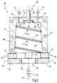
- Fig. 3 is a device according to a second embodiment of the invention in its entirety with the reference number Designated 120.
- the device 120 differs from that Device 10 according to FIG. 1 mainly by the train 122 instead the pin 100 to 104.
- the Device 120 in Fig. 3 without a plastic product in the Interior 14 shown.
- here is another one first locking element recognizable, that for the sake of simplicity is also designated by reference numeral 44.
- the train 122 runs on the inner wall 106 of the receptacle 12 along a continuous, spiral Train. This has the consequence that the in the direction of arrows 72nd incoming cooling air also runs along such a spiral Web around a recorded plastic product moves, which is indicated by the arrows 124 and 126. All in all becomes the path of a single air particle in contact with the surface section 22, 28 of the plastic product to be cooled thereby longer, so that for the air particle more time is available to heat energy from the plastic product to record.
- FIG. 120 Another difference of the device 120 compared to FIG the device 10 is that the plastic product to be cooled no longer in the device 120 within the receptacle 12 is held by the gripping device 80. Accordingly can the gripping device 80 in the device 120 in a Rest position to be retracted at the bottom of the Bottom plate 84 flush with the inside 128 of the bottom 18 of the Recording 12 completes.
- the plastic product to be cooled is only in the device 120 by the locking elements 44th held to 54 against which it is due to the incoming cooling air is pressed.
- the cream jar 16 just pulled off a core 142 that is on one half of the tool 144 of the plastic injection molding machine not shown here is arranged.
- the core 142 projects into the mold cavity of a not shown here second tool half, the two tool halves together in a manner known per se, the mold cavity form for the cream jar 16.
- the cream jar can differ from the illustration shown here 16 also with a scraper ring or something similar from be lifted up from the bottom of the core 142 and then be drawn into the receptacle 12 by means of a vacuum.
- the device 140 differs from those previously described Devices further by protrusions 146 which are formed here by saddle-like protruding rails.
- the rails extend substantially parallel to the Longitudinal central axis 64 of the receptacle 12.
- the Device 140 only second locking elements 148, 150 from below reach under the lower edge 151 of the cream jar 16 if this is drawn into the receptacle 12. This corresponds to the Position of the second locking elements 48, 50, 52, as shown in Fig. 1 is shown.
- Each of the second blocking elements 148, 150 has a channel 152 on, through the cooling air directly to the insides 20, 26 of the Cream jar 16 is performed.
- the cooling air is here both blown into the receptacle 12 from above and from below. Consequently it reaches the inside 20, 26 of the cream jar 16 in this embodiment with a lower, yet not preheated temperature. Otherwise the function corresponds the device 140 but the device according to FIG. 1.
- the device 160 differentiates differs primarily from the device 140 according to FIG. 4 in that the cooling air is completely from below, i.e. of the Side of the insertion opening 42, blown into the receptacle 12 becomes.
- the second blocking elements 148, 150 each have two air inlets 162, 164, from which the cooling air flows into the receptacle 12 in the direction of the arrows 166, 168.
- the outlets 170 arranged over which the injected cooling air Vacuumed in the direction of arrows 172 becomes.
- the cooling air in others Embodiments of the invention also from other positions the receptacle 12 blown in and, if necessary, via outlets 170 be sucked off at another end.
- the inner wall 106 of the receptacle 12 alternatively or in addition to the pin 100 to 104 or the Train 122 structured by grooves, grooves, holes or the like, which is also a swirl of the incoming cooling air causes.
Landscapes
- Engineering & Computer Science (AREA)
- Manufacturing & Machinery (AREA)
- Mechanical Engineering (AREA)
- Moulds For Moulding Plastics Or The Like (AREA)
- Injection Moulding Of Plastics Or The Like (AREA)
Applications Claiming Priority (4)
| Application Number | Priority Date | Filing Date | Title |
|---|---|---|---|
| DE19929989 | 1999-06-30 | ||
| DE19929989 | 1999-06-30 | ||
| DE19963572 | 1999-12-29 | ||
| DE19963572A DE19963572C2 (de) | 1999-06-30 | 1999-12-29 | Vorrichtung und Verfahren zum Handhaben eines Kunststofferzeugnisses |
Publications (2)
| Publication Number | Publication Date |
|---|---|
| EP1065035A2 true EP1065035A2 (fr) | 2001-01-03 |
| EP1065035A3 EP1065035A3 (fr) | 2002-12-18 |
Family
ID=26053991
Family Applications (1)
| Application Number | Title | Priority Date | Filing Date |
|---|---|---|---|
| EP00113130A Withdrawn EP1065035A3 (fr) | 1999-06-30 | 2000-06-29 | Dispositif et procédé pour manipuler un produit en matière plastique |
Country Status (2)
| Country | Link |
|---|---|
| EP (1) | EP1065035A3 (fr) |
| JP (1) | JP2001018265A (fr) |
Cited By (5)
| Publication number | Priority date | Publication date | Assignee | Title |
|---|---|---|---|---|
| WO2003022548A1 (fr) * | 2001-09-10 | 2003-03-20 | Husky Injection Molding Systems Ltd. | Procede et ensemble de refroidissement apres moulage pour bagues d'articles moules |
| WO2006092651A1 (fr) * | 2005-03-01 | 2006-09-08 | Sacmi Cooperativa Meccanici Imola Societa' Cooperativa | Appareils pour moulage par compression, conditionnement thermique, transport et inspection d’objets |
| US20160200012A1 (en) * | 2015-01-13 | 2016-07-14 | YUDO ValuePro Lab Canada Inc. | Post-mold cooling method and apparatus with cyclone cooling effect |
| CN110239048A (zh) * | 2019-05-31 | 2019-09-17 | 张少学 | 一种具有温控系统的注塑模具 |
| WO2021237866A1 (fr) * | 2020-05-29 | 2021-12-02 | 南京工业职业技术大学 | Tête d'extracteur en plastique de type à languette souple améliorée |
Families Citing this family (1)
| Publication number | Priority date | Publication date | Assignee | Title |
|---|---|---|---|---|
| CN103158230A (zh) * | 2013-03-28 | 2013-06-19 | 苏州工业园区协利塑胶有限公司 | 一种注塑刀套定型治具 |
Family Cites Families (4)
| Publication number | Priority date | Publication date | Assignee | Title |
|---|---|---|---|---|
| FR2561166B1 (fr) * | 1984-03-16 | 1986-10-10 | Pont A Mousson | Procede de fabrication de bouteilles en matiere plastique a partir d'ebauches creuses obtenues par moulage et dispositifs pour la mise en oeuvre de ce procede |
| JPH0790595B2 (ja) * | 1990-10-15 | 1995-10-04 | 日精エー・エス・ビー機械株式会社 | プリフォームの冷却装置 |
| US5114327A (en) * | 1991-01-25 | 1992-05-19 | Williamson James T | Rapid cooling apparatus for an injection molding machine |
| DE4212115C2 (de) * | 1992-04-10 | 2003-04-03 | Sig Corpoplast Gmbh & Co Kg | Transporteinrichtung zum Halten und Kühlen noch warmer Vorformlinge |
-
2000
- 2000-06-28 JP JP2000194734A patent/JP2001018265A/ja active Pending
- 2000-06-29 EP EP00113130A patent/EP1065035A3/fr not_active Withdrawn
Cited By (8)
| Publication number | Priority date | Publication date | Assignee | Title |
|---|---|---|---|---|
| WO2003022548A1 (fr) * | 2001-09-10 | 2003-03-20 | Husky Injection Molding Systems Ltd. | Procede et ensemble de refroidissement apres moulage pour bagues d'articles moules |
| US6802705B2 (en) | 2001-09-10 | 2004-10-12 | Husky Injection Molding Systems Ltd. | Post mold cooling assembly for molded article neck finishes |
| WO2006092651A1 (fr) * | 2005-03-01 | 2006-09-08 | Sacmi Cooperativa Meccanici Imola Societa' Cooperativa | Appareils pour moulage par compression, conditionnement thermique, transport et inspection d’objets |
| US20160200012A1 (en) * | 2015-01-13 | 2016-07-14 | YUDO ValuePro Lab Canada Inc. | Post-mold cooling method and apparatus with cyclone cooling effect |
| US10011052B2 (en) * | 2015-01-13 | 2018-07-03 | YUDO ValuePro Lab Canada Inc. | Post-mold cooling method and apparatus with cyclone cooling effect |
| US10137610B2 (en) | 2015-01-13 | 2018-11-27 | YUDO ValuePro Lab Canada Inc. | Post-mold cooling method and apparatus with cyclone cooling effect |
| CN110239048A (zh) * | 2019-05-31 | 2019-09-17 | 张少学 | 一种具有温控系统的注塑模具 |
| WO2021237866A1 (fr) * | 2020-05-29 | 2021-12-02 | 南京工业职业技术大学 | Tête d'extracteur en plastique de type à languette souple améliorée |
Also Published As
| Publication number | Publication date |
|---|---|
| JP2001018265A (ja) | 2001-01-23 |
| EP1065035A3 (fr) | 2002-12-18 |
Similar Documents
| Publication | Publication Date | Title |
|---|---|---|
| DE69618399T2 (de) | Stanzmethode bei mehrschichtbehälter | |
| DE60320146T2 (de) | Vorrichtung und verfahren zum auswerfen von spritzgussteilen aus einer spritzgiessform | |
| DE69110819T2 (de) | Spritzgiesssystem zum Herstellen einer hinterschnittenen Vorformung. | |
| EP1123189B2 (fr) | Machine de moulage par injection et procede de production de pieces moulees par injection en forme d'enveloppes, notamment de preformes | |
| EP0311875A2 (fr) | Procédé et appareil pour fabriquer des articles multicouches | |
| EP1984161B1 (fr) | Système de réception | |
| EP0062144B1 (fr) | Procédé et appareil pour calibrer des corps creux en matière thermoplastique orientés biaxialement | |
| DE3872322T2 (de) | Blasformen. | |
| DE60213074T2 (de) | Anlage und verfahren zur herstellung flexibler rohre aus kunststoff, wobei das formen des kopfes oben auf der schürze durch sich kontinuierlich bewegende werkzeuge durchgeführt wird | |
| DE1679959B1 (de) | Vorrichtung zum abtrennen des grates | |
| DE4129468C2 (de) | Verfahren zum Herstellen eines Gleitlagers für ein bewegliches Funktionsteil, Vorrichtung zur Durchführung dieses Verfahrens und Lagerungsteil des Gleitlagers | |
| EP1065035A2 (fr) | Dispositif et procédé pour manipuler un produit en matière plastique | |
| DE69022576T2 (de) | Verfahren und Vorrichtung zum Spritzgiessen mit direktem Angusssystem. | |
| DE19963572C2 (de) | Vorrichtung und Verfahren zum Handhaben eines Kunststofferzeugnisses | |
| DE20115180U1 (de) | Werkzeugkopf zur Extrusion eines rohrförmigen Stranges aus mindestens einer thermoplastischen Kunststoffschmelze für die Herstellung von Blasfolien | |
| DE10024625B4 (de) | Formnest für die Kunststoffverarbeitung | |
| DE1679963B2 (de) | Vorrichtung zum Steuern der Öffnungsund Schließbewegung der Halsformteile und der Abstreifeinrichtung bei einer Spritz blasmaschine | |
| DE3143748C2 (de) | Form zum Spritzgießen oder Preßspritzen von Kautschuk oder anderen plastischen, wärmehärtbaren Werkstoffen | |
| DE10355018A1 (de) | Formnestaufbau | |
| EP0436786B1 (fr) | Procédé et dispositif pour la fabrication de boulettes extrudées | |
| DE1604575A1 (de) | Vorrichtung zum Herstellen von Hohlkoerpern aus thermoplastischem Material im Blasverfahren | |
| EP3197655B1 (fr) | Procédé et dispositif pour réaliser un contour de col optimisé sur des préformes | |
| DE4119582C2 (de) | Spritzgießwerkzeug zur Herstellung von Formkörpern, insbesondere von Radialwälzlagerkäfigen, aus Kunststoff | |
| CH689204A5 (de) | Verfahren zur Befuellung einer Matrize zur Anformung eines Tubenkopfes an ein Tubenrohr. | |
| DE1479536A1 (de) | Verfahren zum Herstellen von Hohlkoerpern aus thermoplastischem Kunststoff im Blasverfahren |
Legal Events
| Date | Code | Title | Description |
|---|---|---|---|
| PUAI | Public reference made under article 153(3) epc to a published international application that has entered the european phase |
Free format text: ORIGINAL CODE: 0009012 |
|
| AK | Designated contracting states |
Kind code of ref document: A2 Designated state(s): AT BE CH CY DE DK ES FI FR GB GR IE IT LI LU MC NL PT SE |
|
| AX | Request for extension of the european patent |
Free format text: AL;LT;LV;MK;RO;SI |
|
| RAP1 | Party data changed (applicant data changed or rights of an application transferred) |
Owner name: HEKUMA GMBH |
|
| PUAL | Search report despatched |
Free format text: ORIGINAL CODE: 0009013 |
|
| AK | Designated contracting states |
Kind code of ref document: A3 Designated state(s): AT BE CH CY DE DK ES FI FR GB GR IE IT LI LU MC NL PT SE |
|
| AX | Request for extension of the european patent |
Free format text: AL;LT;LV;MK;RO;SI |
|
| AKX | Designation fees paid | ||
| REG | Reference to a national code |
Ref country code: DE Ref legal event code: 8566 |
|
| STAA | Information on the status of an ep patent application or granted ep patent |
Free format text: STATUS: THE APPLICATION IS DEEMED TO BE WITHDRAWN |
|
| 18D | Application deemed to be withdrawn |
Effective date: 20030619 |