EP1065091A2 - Vorrichtung zur Steuerung eines Antriebsmotors - Google Patents
Vorrichtung zur Steuerung eines Antriebsmotors Download PDFInfo
- Publication number
- EP1065091A2 EP1065091A2 EP00113918A EP00113918A EP1065091A2 EP 1065091 A2 EP1065091 A2 EP 1065091A2 EP 00113918 A EP00113918 A EP 00113918A EP 00113918 A EP00113918 A EP 00113918A EP 1065091 A2 EP1065091 A2 EP 1065091A2
- Authority
- EP
- European Patent Office
- Prior art keywords
- vehicle
- driving force
- driving
- condition
- brake pedal
- Prior art date
- Legal status (The legal status is an assumption and is not a legal conclusion. Google has not performed a legal analysis and makes no representation as to the accuracy of the status listed.)
- Withdrawn
Links
Images





Classifications
-
- B—PERFORMING OPERATIONS; TRANSPORTING
- B60—VEHICLES IN GENERAL
- B60W—CONJOINT CONTROL OF VEHICLE SUB-UNITS OF DIFFERENT TYPE OR DIFFERENT FUNCTION; CONTROL SYSTEMS SPECIALLY ADAPTED FOR HYBRID VEHICLES; ROAD VEHICLE DRIVE CONTROL SYSTEMS FOR PURPOSES NOT RELATED TO THE CONTROL OF A PARTICULAR SUB-UNIT
- B60W30/00—Purposes of road vehicle drive control systems not related to the control of a particular sub-unit, e.g. of systems using conjoint control of vehicle sub-units
- B60W30/18—Propelling the vehicle
- B60W30/18009—Propelling the vehicle related to particular drive situations
- B60W30/18063—Creeping
-
- B—PERFORMING OPERATIONS; TRANSPORTING
- B60—VEHICLES IN GENERAL
- B60W—CONJOINT CONTROL OF VEHICLE SUB-UNITS OF DIFFERENT TYPE OR DIFFERENT FUNCTION; CONTROL SYSTEMS SPECIALLY ADAPTED FOR HYBRID VEHICLES; ROAD VEHICLE DRIVE CONTROL SYSTEMS FOR PURPOSES NOT RELATED TO THE CONTROL OF A PARTICULAR SUB-UNIT
- B60W20/00—Control systems specially adapted for hybrid vehicles
- B60W20/10—Controlling the power contribution of each of the prime movers to meet required power demand
- B60W20/15—Control strategies specially adapted for achieving a particular effect
-
- B—PERFORMING OPERATIONS; TRANSPORTING
- B60—VEHICLES IN GENERAL
- B60K—ARRANGEMENT OR MOUNTING OF PROPULSION UNITS OR OF TRANSMISSIONS IN VEHICLES; ARRANGEMENT OR MOUNTING OF PLURAL DIVERSE PRIME-MOVERS IN VEHICLES; AUXILIARY DRIVES FOR VEHICLES; INSTRUMENTATION OR DASHBOARDS FOR VEHICLES; ARRANGEMENTS IN CONNECTION WITH COOLING, AIR INTAKE, GAS EXHAUST OR FUEL SUPPLY OF PROPULSION UNITS IN VEHICLES
- B60K6/00—Arrangement or mounting of plural diverse prime-movers for mutual or common propulsion, e.g. hybrid propulsion systems comprising electric motors and internal combustion engines
- B60K6/20—Arrangement or mounting of plural diverse prime-movers for mutual or common propulsion, e.g. hybrid propulsion systems comprising electric motors and internal combustion engines the prime-movers consisting of electric motors and internal combustion engines, e.g. HEVs
- B60K6/42—Arrangement or mounting of plural diverse prime-movers for mutual or common propulsion, e.g. hybrid propulsion systems comprising electric motors and internal combustion engines the prime-movers consisting of electric motors and internal combustion engines, e.g. HEVs characterised by the architecture of the hybrid electric vehicle
- B60K6/48—Parallel type
-
- B—PERFORMING OPERATIONS; TRANSPORTING
- B60—VEHICLES IN GENERAL
- B60K—ARRANGEMENT OR MOUNTING OF PROPULSION UNITS OR OF TRANSMISSIONS IN VEHICLES; ARRANGEMENT OR MOUNTING OF PLURAL DIVERSE PRIME-MOVERS IN VEHICLES; AUXILIARY DRIVES FOR VEHICLES; INSTRUMENTATION OR DASHBOARDS FOR VEHICLES; ARRANGEMENTS IN CONNECTION WITH COOLING, AIR INTAKE, GAS EXHAUST OR FUEL SUPPLY OF PROPULSION UNITS IN VEHICLES
- B60K6/00—Arrangement or mounting of plural diverse prime-movers for mutual or common propulsion, e.g. hybrid propulsion systems comprising electric motors and internal combustion engines
- B60K6/20—Arrangement or mounting of plural diverse prime-movers for mutual or common propulsion, e.g. hybrid propulsion systems comprising electric motors and internal combustion engines the prime-movers consisting of electric motors and internal combustion engines, e.g. HEVs
- B60K6/50—Architecture of the driveline characterised by arrangement or kind of transmission units
- B60K6/54—Transmission for changing ratio
- B60K6/543—Transmission for changing ratio the transmission being a continuously variable transmission
-
- B—PERFORMING OPERATIONS; TRANSPORTING
- B60—VEHICLES IN GENERAL
- B60T—VEHICLE BRAKE CONTROL SYSTEMS OR PARTS THEREOF; BRAKE CONTROL SYSTEMS OR PARTS THEREOF, IN GENERAL; ARRANGEMENT OF BRAKING ELEMENTS ON VEHICLES IN GENERAL; PORTABLE DEVICES FOR PREVENTING UNWANTED MOVEMENT OF VEHICLES; VEHICLE MODIFICATIONS TO FACILITATE COOLING OF BRAKES
- B60T7/00—Brake-action initiating means
- B60T7/02—Brake-action initiating means for personal initiation
- B60T7/04—Brake-action initiating means for personal initiation foot actuated
- B60T7/042—Brake-action initiating means for personal initiation foot actuated by electrical means, e.g. using travel or force sensors
-
- B—PERFORMING OPERATIONS; TRANSPORTING
- B60—VEHICLES IN GENERAL
- B60T—VEHICLE BRAKE CONTROL SYSTEMS OR PARTS THEREOF; BRAKE CONTROL SYSTEMS OR PARTS THEREOF, IN GENERAL; ARRANGEMENT OF BRAKING ELEMENTS ON VEHICLES IN GENERAL; PORTABLE DEVICES FOR PREVENTING UNWANTED MOVEMENT OF VEHICLES; VEHICLE MODIFICATIONS TO FACILITATE COOLING OF BRAKES
- B60T7/00—Brake-action initiating means
- B60T7/12—Brake-action initiating means for automatic initiation; for initiation not subject to will of driver or passenger
-
- B—PERFORMING OPERATIONS; TRANSPORTING
- B60—VEHICLES IN GENERAL
- B60W—CONJOINT CONTROL OF VEHICLE SUB-UNITS OF DIFFERENT TYPE OR DIFFERENT FUNCTION; CONTROL SYSTEMS SPECIALLY ADAPTED FOR HYBRID VEHICLES; ROAD VEHICLE DRIVE CONTROL SYSTEMS FOR PURPOSES NOT RELATED TO THE CONTROL OF A PARTICULAR SUB-UNIT
- B60W10/00—Conjoint control of vehicle sub-units of different type or different function
- B60W10/04—Conjoint control of vehicle sub-units of different type or different function including control of propulsion units
-
- B—PERFORMING OPERATIONS; TRANSPORTING
- B60—VEHICLES IN GENERAL
- B60W—CONJOINT CONTROL OF VEHICLE SUB-UNITS OF DIFFERENT TYPE OR DIFFERENT FUNCTION; CONTROL SYSTEMS SPECIALLY ADAPTED FOR HYBRID VEHICLES; ROAD VEHICLE DRIVE CONTROL SYSTEMS FOR PURPOSES NOT RELATED TO THE CONTROL OF A PARTICULAR SUB-UNIT
- B60W10/00—Conjoint control of vehicle sub-units of different type or different function
- B60W10/04—Conjoint control of vehicle sub-units of different type or different function including control of propulsion units
- B60W10/06—Conjoint control of vehicle sub-units of different type or different function including control of propulsion units including control of combustion engines
-
- B—PERFORMING OPERATIONS; TRANSPORTING
- B60—VEHICLES IN GENERAL
- B60W—CONJOINT CONTROL OF VEHICLE SUB-UNITS OF DIFFERENT TYPE OR DIFFERENT FUNCTION; CONTROL SYSTEMS SPECIALLY ADAPTED FOR HYBRID VEHICLES; ROAD VEHICLE DRIVE CONTROL SYSTEMS FOR PURPOSES NOT RELATED TO THE CONTROL OF A PARTICULAR SUB-UNIT
- B60W10/00—Conjoint control of vehicle sub-units of different type or different function
- B60W10/10—Conjoint control of vehicle sub-units of different type or different function including control of change-speed gearings
- B60W10/101—Infinitely variable gearings
-
- B—PERFORMING OPERATIONS; TRANSPORTING
- B60—VEHICLES IN GENERAL
- B60W—CONJOINT CONTROL OF VEHICLE SUB-UNITS OF DIFFERENT TYPE OR DIFFERENT FUNCTION; CONTROL SYSTEMS SPECIALLY ADAPTED FOR HYBRID VEHICLES; ROAD VEHICLE DRIVE CONTROL SYSTEMS FOR PURPOSES NOT RELATED TO THE CONTROL OF A PARTICULAR SUB-UNIT
- B60W10/00—Conjoint control of vehicle sub-units of different type or different function
- B60W10/18—Conjoint control of vehicle sub-units of different type or different function including control of braking systems
-
- B—PERFORMING OPERATIONS; TRANSPORTING
- B60—VEHICLES IN GENERAL
- B60W—CONJOINT CONTROL OF VEHICLE SUB-UNITS OF DIFFERENT TYPE OR DIFFERENT FUNCTION; CONTROL SYSTEMS SPECIALLY ADAPTED FOR HYBRID VEHICLES; ROAD VEHICLE DRIVE CONTROL SYSTEMS FOR PURPOSES NOT RELATED TO THE CONTROL OF A PARTICULAR SUB-UNIT
- B60W30/00—Purposes of road vehicle drive control systems not related to the control of a particular sub-unit, e.g. of systems using conjoint control of vehicle sub-units
- B60W30/18—Propelling the vehicle
- B60W30/18009—Propelling the vehicle related to particular drive situations
- B60W30/181—Preparing for stopping
-
- B—PERFORMING OPERATIONS; TRANSPORTING
- B60—VEHICLES IN GENERAL
- B60W—CONJOINT CONTROL OF VEHICLE SUB-UNITS OF DIFFERENT TYPE OR DIFFERENT FUNCTION; CONTROL SYSTEMS SPECIALLY ADAPTED FOR HYBRID VEHICLES; ROAD VEHICLE DRIVE CONTROL SYSTEMS FOR PURPOSES NOT RELATED TO THE CONTROL OF A PARTICULAR SUB-UNIT
- B60W30/00—Purposes of road vehicle drive control systems not related to the control of a particular sub-unit, e.g. of systems using conjoint control of vehicle sub-units
- B60W30/18—Propelling the vehicle
- B60W30/1819—Propulsion control with control means using analogue circuits, relays or mechanical links
-
- B—PERFORMING OPERATIONS; TRANSPORTING
- B60—VEHICLES IN GENERAL
- B60L—PROPULSION OF ELECTRICALLY-PROPELLED VEHICLES; SUPPLYING ELECTRIC POWER FOR AUXILIARY EQUIPMENT OF ELECTRICALLY-PROPELLED VEHICLES; ELECTRODYNAMIC BRAKE SYSTEMS FOR VEHICLES IN GENERAL; MAGNETIC SUSPENSION OR LEVITATION FOR VEHICLES; MONITORING OPERATING VARIABLES OF ELECTRICALLY-PROPELLED VEHICLES; ELECTRIC SAFETY DEVICES FOR ELECTRICALLY-PROPELLED VEHICLES
- B60L2240/00—Control parameters of input or output; Target parameters
- B60L2240/40—Drive Train control parameters
- B60L2240/48—Drive Train control parameters related to transmissions
- B60L2240/486—Operating parameters
-
- B—PERFORMING OPERATIONS; TRANSPORTING
- B60—VEHICLES IN GENERAL
- B60L—PROPULSION OF ELECTRICALLY-PROPELLED VEHICLES; SUPPLYING ELECTRIC POWER FOR AUXILIARY EQUIPMENT OF ELECTRICALLY-PROPELLED VEHICLES; ELECTRODYNAMIC BRAKE SYSTEMS FOR VEHICLES IN GENERAL; MAGNETIC SUSPENSION OR LEVITATION FOR VEHICLES; MONITORING OPERATING VARIABLES OF ELECTRICALLY-PROPELLED VEHICLES; ELECTRIC SAFETY DEVICES FOR ELECTRICALLY-PROPELLED VEHICLES
- B60L2260/00—Operating Modes
- B60L2260/20—Drive modes; Transition between modes
- B60L2260/26—Transition between different drive modes
-
- B—PERFORMING OPERATIONS; TRANSPORTING
- B60—VEHICLES IN GENERAL
- B60L—PROPULSION OF ELECTRICALLY-PROPELLED VEHICLES; SUPPLYING ELECTRIC POWER FOR AUXILIARY EQUIPMENT OF ELECTRICALLY-PROPELLED VEHICLES; ELECTRODYNAMIC BRAKE SYSTEMS FOR VEHICLES IN GENERAL; MAGNETIC SUSPENSION OR LEVITATION FOR VEHICLES; MONITORING OPERATING VARIABLES OF ELECTRICALLY-PROPELLED VEHICLES; ELECTRIC SAFETY DEVICES FOR ELECTRICALLY-PROPELLED VEHICLES
- B60L2270/00—Problem solutions or means not otherwise provided for
- B60L2270/10—Emission reduction
- B60L2270/14—Emission reduction of noise
- B60L2270/145—Structure borne vibrations
-
- B—PERFORMING OPERATIONS; TRANSPORTING
- B60—VEHICLES IN GENERAL
- B60W—CONJOINT CONTROL OF VEHICLE SUB-UNITS OF DIFFERENT TYPE OR DIFFERENT FUNCTION; CONTROL SYSTEMS SPECIALLY ADAPTED FOR HYBRID VEHICLES; ROAD VEHICLE DRIVE CONTROL SYSTEMS FOR PURPOSES NOT RELATED TO THE CONTROL OF A PARTICULAR SUB-UNIT
- B60W20/00—Control systems specially adapted for hybrid vehicles
-
- B—PERFORMING OPERATIONS; TRANSPORTING
- B60—VEHICLES IN GENERAL
- B60W—CONJOINT CONTROL OF VEHICLE SUB-UNITS OF DIFFERENT TYPE OR DIFFERENT FUNCTION; CONTROL SYSTEMS SPECIALLY ADAPTED FOR HYBRID VEHICLES; ROAD VEHICLE DRIVE CONTROL SYSTEMS FOR PURPOSES NOT RELATED TO THE CONTROL OF A PARTICULAR SUB-UNIT
- B60W50/00—Details of control systems for road vehicle drive control not related to the control of a particular sub-unit, e.g. process diagnostic or vehicle driver interfaces
- B60W50/02—Ensuring safety in case of control system failures, e.g. by diagnosing, circumventing or fixing failures
- B60W50/0205—Diagnosing or detecting failures; Failure detection models
- B60W2050/021—Means for detecting failure or malfunction
-
- B—PERFORMING OPERATIONS; TRANSPORTING
- B60—VEHICLES IN GENERAL
- B60W—CONJOINT CONTROL OF VEHICLE SUB-UNITS OF DIFFERENT TYPE OR DIFFERENT FUNCTION; CONTROL SYSTEMS SPECIALLY ADAPTED FOR HYBRID VEHICLES; ROAD VEHICLE DRIVE CONTROL SYSTEMS FOR PURPOSES NOT RELATED TO THE CONTROL OF A PARTICULAR SUB-UNIT
- B60W2520/00—Input parameters relating to overall vehicle dynamics
- B60W2520/10—Longitudinal speed
-
- B—PERFORMING OPERATIONS; TRANSPORTING
- B60—VEHICLES IN GENERAL
- B60W—CONJOINT CONTROL OF VEHICLE SUB-UNITS OF DIFFERENT TYPE OR DIFFERENT FUNCTION; CONTROL SYSTEMS SPECIALLY ADAPTED FOR HYBRID VEHICLES; ROAD VEHICLE DRIVE CONTROL SYSTEMS FOR PURPOSES NOT RELATED TO THE CONTROL OF A PARTICULAR SUB-UNIT
- B60W2540/00—Input parameters relating to occupants
- B60W2540/12—Brake pedal position
-
- B—PERFORMING OPERATIONS; TRANSPORTING
- B60—VEHICLES IN GENERAL
- B60W—CONJOINT CONTROL OF VEHICLE SUB-UNITS OF DIFFERENT TYPE OR DIFFERENT FUNCTION; CONTROL SYSTEMS SPECIALLY ADAPTED FOR HYBRID VEHICLES; ROAD VEHICLE DRIVE CONTROL SYSTEMS FOR PURPOSES NOT RELATED TO THE CONTROL OF A PARTICULAR SUB-UNIT
- B60W2710/00—Output or target parameters relating to a particular sub-units
- B60W2710/06—Combustion engines, Gas turbines
- B60W2710/0616—Position of fuel or air injector
-
- B—PERFORMING OPERATIONS; TRANSPORTING
- B60—VEHICLES IN GENERAL
- B60W—CONJOINT CONTROL OF VEHICLE SUB-UNITS OF DIFFERENT TYPE OR DIFFERENT FUNCTION; CONTROL SYSTEMS SPECIALLY ADAPTED FOR HYBRID VEHICLES; ROAD VEHICLE DRIVE CONTROL SYSTEMS FOR PURPOSES NOT RELATED TO THE CONTROL OF A PARTICULAR SUB-UNIT
- B60W2710/00—Output or target parameters relating to a particular sub-units
- B60W2710/10—Change speed gearings
- B60W2710/105—Output torque
-
- B—PERFORMING OPERATIONS; TRANSPORTING
- B60—VEHICLES IN GENERAL
- B60W—CONJOINT CONTROL OF VEHICLE SUB-UNITS OF DIFFERENT TYPE OR DIFFERENT FUNCTION; CONTROL SYSTEMS SPECIALLY ADAPTED FOR HYBRID VEHICLES; ROAD VEHICLE DRIVE CONTROL SYSTEMS FOR PURPOSES NOT RELATED TO THE CONTROL OF A PARTICULAR SUB-UNIT
- B60W30/00—Purposes of road vehicle drive control systems not related to the control of a particular sub-unit, e.g. of systems using conjoint control of vehicle sub-units
- B60W30/18—Propelling the vehicle
- B60W30/18009—Propelling the vehicle related to particular drive situations
- B60W30/18109—Braking
- B60W30/18118—Hill holding
-
- F—MECHANICAL ENGINEERING; LIGHTING; HEATING; WEAPONS; BLASTING
- F16—ENGINEERING ELEMENTS AND UNITS; GENERAL MEASURES FOR PRODUCING AND MAINTAINING EFFECTIVE FUNCTIONING OF MACHINES OR INSTALLATIONS; THERMAL INSULATION IN GENERAL
- F16H—GEARING
- F16H61/00—Control functions within control units of change-speed- or reversing-gearings for conveying rotary motion ; Control of exclusively fluid gearing, friction gearing, gearings with endless flexible members or other particular types of gearing
- F16H61/66—Control functions within control units of change-speed- or reversing-gearings for conveying rotary motion ; Control of exclusively fluid gearing, friction gearing, gearings with endless flexible members or other particular types of gearing specially adapted for continuously variable gearings
-
- Y—GENERAL TAGGING OF NEW TECHNOLOGICAL DEVELOPMENTS; GENERAL TAGGING OF CROSS-SECTIONAL TECHNOLOGIES SPANNING OVER SEVERAL SECTIONS OF THE IPC; TECHNICAL SUBJECTS COVERED BY FORMER USPC CROSS-REFERENCE ART COLLECTIONS [XRACs] AND DIGESTS
- Y02—TECHNOLOGIES OR APPLICATIONS FOR MITIGATION OR ADAPTATION AGAINST CLIMATE CHANGE
- Y02T—CLIMATE CHANGE MITIGATION TECHNOLOGIES RELATED TO TRANSPORTATION
- Y02T10/00—Road transport of goods or passengers
- Y02T10/10—Internal combustion engine [ICE] based vehicles
- Y02T10/40—Engine management systems
-
- Y—GENERAL TAGGING OF NEW TECHNOLOGICAL DEVELOPMENTS; GENERAL TAGGING OF CROSS-SECTIONAL TECHNOLOGIES SPANNING OVER SEVERAL SECTIONS OF THE IPC; TECHNICAL SUBJECTS COVERED BY FORMER USPC CROSS-REFERENCE ART COLLECTIONS [XRACs] AND DIGESTS
- Y02—TECHNOLOGIES OR APPLICATIONS FOR MITIGATION OR ADAPTATION AGAINST CLIMATE CHANGE
- Y02T—CLIMATE CHANGE MITIGATION TECHNOLOGIES RELATED TO TRANSPORTATION
- Y02T10/00—Road transport of goods or passengers
- Y02T10/60—Other road transportation technologies with climate change mitigation effect
- Y02T10/62—Hybrid vehicles
-
- Y—GENERAL TAGGING OF NEW TECHNOLOGICAL DEVELOPMENTS; GENERAL TAGGING OF CROSS-SECTIONAL TECHNOLOGIES SPANNING OVER SEVERAL SECTIONS OF THE IPC; TECHNICAL SUBJECTS COVERED BY FORMER USPC CROSS-REFERENCE ART COLLECTIONS [XRACs] AND DIGESTS
- Y10—TECHNICAL SUBJECTS COVERED BY FORMER USPC
- Y10S—TECHNICAL SUBJECTS COVERED BY FORMER USPC CROSS-REFERENCE ART COLLECTIONS [XRACs] AND DIGESTS
- Y10S903/00—Hybrid electric vehicles, HEVS
- Y10S903/902—Prime movers comprising electrical and internal combustion motors
- Y10S903/903—Prime movers comprising electrical and internal combustion motors having energy storing means, e.g. battery, capacitor
- Y10S903/904—Component specially adapted for hev
- Y10S903/915—Specific drive or transmission adapted for hev
- Y10S903/917—Specific drive or transmission adapted for hev with transmission for changing gear ratio
- Y10S903/918—Continuously variable
-
- Y—GENERAL TAGGING OF NEW TECHNOLOGICAL DEVELOPMENTS; GENERAL TAGGING OF CROSS-SECTIONAL TECHNOLOGIES SPANNING OVER SEVERAL SECTIONS OF THE IPC; TECHNICAL SUBJECTS COVERED BY FORMER USPC CROSS-REFERENCE ART COLLECTIONS [XRACs] AND DIGESTS
- Y10—TECHNICAL SUBJECTS COVERED BY FORMER USPC
- Y10S—TECHNICAL SUBJECTS COVERED BY FORMER USPC CROSS-REFERENCE ART COLLECTIONS [XRACs] AND DIGESTS
- Y10S903/00—Hybrid electric vehicles, HEVS
- Y10S903/902—Prime movers comprising electrical and internal combustion motors
- Y10S903/903—Prime movers comprising electrical and internal combustion motors having energy storing means, e.g. battery, capacitor
- Y10S903/945—Characterized by control of gearing, e.g. control of transmission ratio
-
- Y—GENERAL TAGGING OF NEW TECHNOLOGICAL DEVELOPMENTS; GENERAL TAGGING OF CROSS-SECTIONAL TECHNOLOGIES SPANNING OVER SEVERAL SECTIONS OF THE IPC; TECHNICAL SUBJECTS COVERED BY FORMER USPC CROSS-REFERENCE ART COLLECTIONS [XRACs] AND DIGESTS
- Y10—TECHNICAL SUBJECTS COVERED BY FORMER USPC
- Y10S—TECHNICAL SUBJECTS COVERED BY FORMER USPC CROSS-REFERENCE ART COLLECTIONS [XRACs] AND DIGESTS
- Y10S903/00—Hybrid electric vehicles, HEVS
- Y10S903/902—Prime movers comprising electrical and internal combustion motors
- Y10S903/903—Prime movers comprising electrical and internal combustion motors having energy storing means, e.g. battery, capacitor
- Y10S903/947—Characterized by control of braking, e.g. blending of regeneration, friction braking
Definitions
- the present invention relates to an apparatus for controlling a driving motor. More particularly, to an apparatus which controls and automatically stops the driving motor of a vehicle while the vehicle stops.
- One known automatic transmission transmits driving force from the driving motor, such as an engine, to driving wheels when the transmission is set in a driving range, such as a D range, and the vehicle moves at a certain or lower vehicle speed when the accelerator pedal is released.
- a vehicle has been developed with a driving force decreasing unit, which decreases the creep driving force when the brake pedal is depressed while the vehicle is in an idling condition and moves at a certain or lower vehicle speed, and a vehicle with a driving motor stopping unit, which automatically stops the driving motor while the vehicle stops in an idling condition.
- the vehicle with an automatic transmission moves slowly as if it creeps along the ground when the transmission is set to a running range, such as a D or R range and the accelerator pedal is released (the driving motor is in an idling condition).
- a running range such as a D or R range and the accelerator pedal is released (the driving motor is in an idling condition).
- the decision to have the driving motor stopping unit stop the driving motor is based on a determination of whether or not the detected vehicle speed becomes 0 km/h.
- the accuracy of the detected vehicle speed is determined by a vehicle speed sensor and an ECU (Electronic Control Unit) calculating vehicle speed based on information obtained from the vehicle speed sensor. For this reason, depending on the detectability of the vehicle speed sensor or throughput of the ECU, the vehicle speed may be regarded as 0 km/h even if the vehicle is not completely stopped. For example, if the vehicle speed sensor cannot detect a minimum vehicle speed of less than 1 km/h, the detected vehicle speed is 0 km/h, notwithstanding that the vehicle is actually moving at a vehicle speed of less than 1 km/h.
- the driving motor stopping unit automatically stops the driving motor, even if the vehicle is not completely stopped. If the creep driving force is greater before automatically stopping the driving motor, a braking force greater than the creep driving force is required in order to stop the vehicle, and a large amount of driving force difference exists until the driving force falls to zero. Therefore, if the driving motor is automatically stopped before the vehicle stops fully and the driving force falls to zero, the vehicle often stops suddenly due to a greater braking force and greater driving force difference.
- the present invention seeks to provide a an apparatus for controlling a driving motor which eliminates sudden stops by the vehicle, even if the driving motor is stopped before the vehicle stops completely.
- an apparatus for controlling and stopping a driving motor for a vehicle which vehicle allows transmission of driving force from a driving motor to driving wheels, irrespective of releasing an accelerator pedal at a certain or lower vehicle speed when a transmission is set to a driving range.
- the apparatus also includes a driving force decreasing unit which switches the driving force based on depression of a brake pedal such that the driving force is made lower when the brake pedal is depressed than when the brake pedal is released, and the apparatus includes means for stopping the driving motor after the driving force is decreased by the driving force decreasing unit.
- a vehicle with an apparatus for controlling and stopping a driving motor, which vehicle allows transmission of driving force from a driving motor to driving wheels, irrespective of releasing an accelerator pedal at a certain or lower vehicle speed when a transmission is set to a driving range.
- the apparatus also includes a driving force decreasing unit which switches the driving force based on a brake pedal being depressed such that the driving force is made lower when the brake pedal is depressed than when the brake pedal is released, and the vehicle is controlled such that the driving motor is stopped after the driving force is decreased by the driving force decreasing unit.
- the depression force of the brake pedal is reduced (i.e., braking force becomes smaller) before stopping the driving motor, and the driving force difference becomes smaller, even if the driving motor is stopped so that the driving force falls to zero. As a result, the vehicle does not stop suddenly if the driving motor is stopped before the vehicle stops completely.
- a certain vehicle speed indicates a vehicle speed just before the vehicle stops. Therefore, if a certain vehicle speed is 5 km/h, as an example in the preferred embodiment, the vehicle speed range "at a certain or lower vehicle speed” includes vehicle speeds from 0 km/h (when the vehicle stops) to 5 km/h.
- the wording "after the driving force is decreased by the driving force decreasing unit" does not include a condition where the driving force is zero.
- a vehicle with an apparatus for controlling and stopping a driving motor can automatically stop the driving motor while the vehicle stops.
- the apparatus is provided with a driving force decreasing unit which decreases creep driving force when the brake pedal is depressed when the driving motor is in an idling condition and the vehicle moves at a certain or lower vehicle speed.
- the apparatus stops the driving motor, it stops the driving motor after the driving force is decreased by the driving force decreasing unit.
- the vehicle is further provided with a braking force control unit which is capable of retaining braking force after the brake pedal is released.
- the vehicle shown in this embodiment is a hybrid type vehicle having an engine 1 and an electric motor 2 as a driving motor, and is provided with a belt-type continuously variable transmission 3 (hereinafter referred to as CVT 3).
- Engine 1 is an internal combustion engine operates on gasoline and the like, and electric motor 2 operates on electricity.
- the driving motor of the vehicle is not restricted merely to an engine or a motor.
- the transmission may be an automatic transmission having a torque converter.
- Engine 1 is controlled at a fuel injection electronic control unit (hereinafter referred to as FI ECU).
- the FI ECU is integrally constructed with a management electronic control unit (hereinafter referred to as MG ECU), and it is incorporated in a fuel injection/management electronic control unit 4 (hereinafter referred to as FI/MG ECU).
- Motor 2 is controlled at a motor electronic control unit 5 (hereinafter referred to as MOT ECU).
- CVT 3 is controlled at a CVT electronic control unit 6 (hereinafter referred to as CVT ECU).
- a drive axle 7 provided with driving wheels 8, is mounted to the CVT 3.
- Each driving wheel 8 is provided with a disc brake 9, which includes a wheel cylinder WC and the like (Fig. 2).
- the wheel cylinders WC of the disc brakes 9 are connected to a master cylinder MC through a braking force control unit BCU.
- the brake switch BSW detects whether or not the brake pedal BP is depressed.
- Engine 1 is an internal combustion engine which makes use of thermal energy.
- Engine 1 drives the driving wheels 8 through CVT 3 and drive axle 7.
- engine 1 may be automatically stopped while the vehicle stops. For this reason, the vehicle is provided with an apparatus for controlling and stopping a driving motor for automatically stopping engine 1 when a certain automatic engine stop condition is satisfied.
- Motor 2 has an assist mode for assisting the engine drive with the use of electric energy from a battery (not shown).
- Motor 2 has a regeneration mode for converting the kinetic energy derived from the rotation of drive axle 7 into electric energy.
- the engine does not require an assist from the assist mode (such as for starting on a down slope or deceleration of the vehicle), the converted electric energy is stored in the battery.
- motor 2 has an actuation mode for actuating engine 1.
- CVT 3 includes an endless belt wound between a drive pulley and a driven pulley to enable a continuously variable gear ratio by changing the winding radius of the endless belt. The winding radius change is achieved by changing each pulley width.
- CVT 3 engages a starting clutch and an output shaft to transmit the output of engine 1 converted by the endless belt into drive axle 7 through gears at the output side of the starting clutch.
- the vehicle equipped with CVT 3 enables creep running while engine 1 is idling, and such a vehicle requires a driving force decreasing unit DDU for decreasing driving force to be utilized for the creep running.
- the driving force decreasing unit DDU is incorporated in CVT 3.
- the driving force decreasing unit DDU variably controls the driving force transmission capacity of the starting clutch, thereby changing the creep driving force.
- the driving force decreasing unit DDU increases driving force when detecting displacement (or backward displacement) of the vehicle.
- the driving force decreasing unit DDU comprises CVT ECU 6 which will be described later.
- the driving force decreasing unit DDU controls the driving force transmission capacity of the starting clutch and switches to the predetermined driving force in each creep condition when CVT ECU 6 determines conditions (hereinafter described) required for a weak creep condition, middle creep condition, strong creep condition or a strong creep condition for driving. Further, the driving force decreasing unit DDU increases the driving force transmission capacity of the starting clutch and switches to the strong creep condition if displacement or backward displacement of the vehicle is detected when starting the vehicle on a slope.
- CVT ECU 6 determines conditions for switching the creep driving force, and it transmits a hydraulic pressure command value to a linear solenoid valve of CVT 3, where the engagement hydraulic pressure of the starting clutch is controlled.
- the driving force decreasing unit DDU the engagement force of the starting clutch is adjusted at CVT 3 based on the hydraulic pressure command value.
- the driving force transmission capacity is therefore changed and the creep driving force is adjusted.
- the driving force decreasing unit DDU decreases the driving force, the fuel consumption of the vehicle is improved. Fuel consumption of the vehicle is improved by reducing loads at engine 1, a hydraulic pump of the starting clutch and the like.
- the term "driving force transmission capacity" indicates the maximum driving force (driving torque) transmitted by the starting clutch. Therefore, if the driving force generated at engine 1 is greater than the driving force transmission capacity, the starting clutch does not transmit the remaining driving force, which is beyond the driving force transmission capacity, to driving wheels 8.
- the driving force decreasing unit DDU transmits the driving force from the driving motor to the driving wheels 8, regardless of the release of the accelerator pedal at a certain or lower vehicle speed when the transmission is set to a running range.
- the driving force decreasing unit DDU also switches driving force in accordance with depression of the brake pedal such that the driving force is made lower when the brake pedal BP is depressed than when the brake pedal BP is released.
- the driving force is switched to a weak condition when the brake pedal BP is depressed in order to improve fuel consumption. Meanwhile, the driving force is switched to a strong condition when the brake pedal BP is released for starting or accelerating of the vehicle, as well as for preventing backward displacement of the vehicle without requiring braking force.
- the creep driving force of the vehicle includes three conditions: (1) a strong condition; (2) a weak condition; and (3) a middle condition between the strong and weak conditions.
- the driving force transmission capacity at each condition is predetermined to be greater in the strong condition, less in the weak condition, and intermediate in the middle condition.
- the strong condition strong creep driving force
- the weak condition weak creep driving force
- the middle condition intermediate creep driving force
- the strong creep condition includes two driving force levels, i.e., a strong level and a weak level.
- the strong level is referred to as a strong creep condition
- the weak level is referred to as a strong creep condition for driving.
- the strong creep condition the driving force is adjusted in order to keep the vehicle stationary on a slope having an inclination angle of 5 degrees.
- the strong creep condition for driving the driving force is adjusted in to be less than that in the strong creep condition.
- the strong creep condition for driving is a preliminary condition before switching to the weak creep condition. In the weak creep condition, almost no driving force is obtained.
- the middle creep condition the driving force is controlled substantially at a mid point between the strong creep condition and the weak creep condition.
- the middle creep condition is an intermediate condition when the driving force is decreased stepwise in the process of switching from the strong creep condition to the weak creep condition.
- the strong creep condition is achieved when the accelerator pedal is released at a certain or lower vehicle speed (idling condition) and the positioning switch PSW selects a running range and when the brake pedal BP is released.
- the strong creep condition the vehicle moves slowly as if it creeps along the ground. If the driver depresses the brake pedal BP in this situation, the weak creep condition is achieved. The vehicle stops or moves at an extremely low speed in the weak creep condition.
- the positioning switch PSW selects a running range means that the transmission is set to a running range.
- Range positions of the positioning switch PSW are selected by a shift lever. These range positions are selected from a P range for parking the vehicle, an N range as a neutral range, an R range for backward running, a D range for normal running, and an L range for obtaining a sudden acceleration or strong engine brake.
- the term "running range" indicates a range position, at which the vehicle can move. In this vehicle, the running range includes the D range, L range and R range.
- a D mode as a normal running mode and an S mode as a sports mode can be selected by a mode switch MSW.
- Information from the positioning switch PSW and the mode switch MSW is transmitted to CVT ECU 6 and a meter 10.
- Meter 10 indicates the range information and the mode information selected by the positioning switch PSW and the mode switch, respectively.
- reduction of the creep driving force is carried out while the positioning switch PSW is set in the D or L range.
- the strong creep condition is retained while the positioning switch PSW is set in the R range.
- the driving force is not transmitted to the driving wheels 8 while the positioning switch PSW is set in the N or P range.
- the driving force transmission capacity is decreased and the driving force is substantially switched to the weak creep condition.
- the FI ECU contained in FI/MG ECU 4 controls the amount of fuel injection to achieve the optimum air fuel ratio, and it also generally controls engine 1.
- Various kinds of information such as a throttle angle and conditions of engine 1 are transmitted to the FI ECU such that engine 1 is controlled based on this information.
- the MG ECU contained in FI/MG ECU 4 mainly controls MOT ECU 5 as well as determining the automatic engine stop conditions and automatic engine actuation conditions.
- the MG ECU receives information regarding the conditions of motor 2 and other information such as the conditions of engine 1 from the FI ECU, and based on this information it sends instructions about the mode switching of motor 2 to MOT ECU 5. Further, the MG ECU receives information such as the conditions of CVT 3, conditions of engine 1, range information of the positioning switch PSW, conditions of motor 2 and the like, and based on this information it determines whether engine 1 should be automatically stopped or automatically actuated.
- MOT ECU 5 controls motor 2 based on a control signal from FI/MG ECU 4.
- the control signal from FI/MG ECU 4 includes mode information instructing actuation of engine 1 by motor 2, assistance of the engine actuation or regeneration of electric energy, and an output required value to motor 2, and MOT ECU 5 sends an order to motor 2 based on this information. Further, MOT ECU 5 receives information from motor 2 and transmits information such as the amount of generated energy and the capacity of the battery to FI/MG ECU 4.
- CVT ECU 6 controls the transmission gear ratio of CVT 3, the driving force transmission capacity of the starting clutch and the like.
- Various kinds of information such as the conditions of CVT 3, conditions of engine 1, range information of the positioning switch PSW and the like is transmitted to CVT ECU 6, and based on this information CVT ECU 6 transmits a signal to CVT 3.
- the signal includes control of the hydraulic pressure of each cylinder provided at the drive pulley and the driven pulley of CVT 3, and control of the hydraulic pressure of the starting clutch. As shown in Fig.
- CVT ECU 6 comprises a control unit CU for the ON/OFF control (shut-off/communicate) of the solenoid valves SV(A), SV(B), which function as the braking force retaining means RU of the braking force control unit BCU.
- CVT ECU 6 transmits a signal for turning ON and OFF the solenoid valves SV(A), SV(B) to the braking force control unit BCU.
- CVT ECU 6 also determines the switching of the creep driving force as well as determining whether the driving force should be increased as a result of detecting displacement (or backward displacement) of the vehicle while the braking force control unit BCU actuates. This information is transmitted to the driving force decreasing unit DDU of CVT 3.
- CVT ECU 6 also comprises a failure-detecting unit DU for detecting a malfunction of the braking force control unit BCU.
- Disk brakes 9 are constructed such that a disk rotor rotatable with driving wheel 8 is pressed between the brake pads moved by the wheel cylinder WC (Fig. 2) and braking force is obtained by the frictional force therebetween. Brake fluid pressure within the master cylinder MC is transmitted to the wheel cylinders WC through the braking force control unit BCU.
- the braking force control unit BCU continuously retains the brake fluid pressure within a wheel cylinder WC, i.e. the braking force after depression of the brake pedal BP is released.
- the braking force control unit BCU comprises a control unit CU within CVT ECU 6. Construction of the braking force control unit BCU will be described later in greater detail with reference to Fig. 2.
- solenoid valves SV(A), SV(B) in the preferred embodiment are the normally open type.
- a driving circuit within the control unit CU starts or stops a supply of electric currents to respective coils of the solenoid valves SV(A), SV(B) to turn ON and OFF the solenoid valves.
- a master cylinder MC is a device for converting a brake pedal depression into hydraulic pressure.
- a master power MP is provided between the master cylinder MC and the brake pedal BP.
- the master power MP enhances braking force by applying negative pressure of engine 1 or compressed air to the driver's brake pedal depression force.
- a brake switch BSW is provided at the brake pedal BP to detect whether or not the brake pedal BP is depressed.
- the driving motor stopping unit incorporated in the vehicle includes the FI/MG ECU, CVT ECU 6 and other elements.
- the driving motor stopping unit enables an automatic engine stop operation while the vehicle stops.
- the automatic engine stop conditions are determined at the FI/MG ECU 4 and CVT ECU 6. The automatic engine stop conditions will be described later.
- FI/MG ECU 4 sends an engine stop order to engine 1 to automatically stop engine 1. Because the driving motor stopping unit automatically stops engine 1, the vehicle's fuel consumption improves.
- the automatic engine stop conditions include conditions required for the weak creep condition, which are determined at the driving force decreasing unit DDU, all of the automatic engine stop conditions are not satisfied unless the conditions for the weak creep conditions are satisfied. Decreasing driving force to the weak creep condition occurs when the vehicle speed becomes 5 km/h. Automatic engine stop operation occurs when the vehicle speed falls to 0 km/h. Therefore, the driving force decreasing unit DDU decreases driving force to the weak creep condition, and thereafter, the driving motor stopping unit automatically stops engine 1 at a vehicle speed of 0 km/h. Therefore, because the driving force is first decreased to the weak creep condition, the driving force difference will be smaller even if engine 1 is automatically stopped and driving force falls to zero.
- the required braking force When the driver intends to stop the vehicle while in the strong creep condition, the required braking force must be greater than the driving force in the strong creep condition. However, because the driving force is first decreased to the weak creep condition before automatically stopping engine 1, the braking force required for stopping the vehicle may be less than that required in the strong creep condition. The vehicle can be stopped even if depression of the brake pedal BP is reduced before automatically stopping engine 1. Therefore, because the driving force difference and braking force is smaller, sudden stops by the vehicle can be prevented even if the driving motor stopping unit automatically stops engine 1 and the driving force falls to zero before the vehicle stops completely.
- FI/MG ECU 4 and CVT ECU 6 determine automatic engine actuation conditions while the driving motor stopping unit automatically stops engine 1. When all of the automatic engine actuation conditions are satisfied, FI/MG ECU 4 sends an engine actuation order to MOT ECU 5. MOT ECU 5 further transmits an engine actuation order to motor 2. Motor 2 then automatically actuates engine 1, and at the same time, the driving force is switched to the strong creep condition. The automatic engine actuation conditions will be described later.
- failure-detecting unit DU detects a malfunction of the braking force control unit BCU, operation of the driving motor stopping unit is prohibited.
- the letter “F_” in front of each signal indicates that the signal is flag information, which is either a 0 or 1.
- the letter “V_” indicates that the signal is numerical information (unit is optional), and the letter “I_” indicates that the signal includes different kinds of information.
- V_MOTTRQ represents an output torque value of motor 2.
- F_MGSTB is a flag showing whether all of the engine stop conditions determined at FI/MG ECU 4 are satisfied. If all the conditions are satisfied, a 1 is provided, and if not, 0 is provided. The automatic engine stop conditions regarding F_MGSTB will be described later. When F_MGSTB and F_CVTOK (hereinafter described) are both set to 1, engine 1 is automatically stopped. When one of these flags is set to 0, engine 1 is automatically actuated.
- V_NEP represents engine speed
- F_MCRPON is a flag indicating whether or not the driving force is in the middle creep condition.
- a 1 is provided in the middle creep condition, and if not, a 0 is provided.
- F_MCRPON is 1, engine 1 is required to blow middle air in the middle creep condition (weaker air than that in the strong creep condition).
- F_AIRSCRP is a strong air demand flag in the strong creep condition. If strong air is required in the strong creep condition, a 1 is provided, and if not, a 0 is given.
- F_MCRPON and F_AIRSCRP are 0, FI/MG ECU 4 blows weak air in the weak creep condition.
- the engine output should be adjusted by blowing air corresponding to the strong creep condition, middle creep condition or the weak creep condition.
- a strong air blow strong air in the strong creep condition
- air blow means the supply of air from an air passage by-passing a throttle valve in engine 1 to an intake pipe positioned downstream from the throttle valve. Air flow is adjusted by controlling the degree of the opening of the air passage.
- F_CVTOK is a flag indicating whether all of the engine stop conditions determined at CVT ECU 6 are satisfied.
- F_CVTTO is a flag indicating whether the oil temperature of CVT 3 is greater than a certain value. If the oil temperature is equal to or greater than the certain value, a 1 is provided, and if the oil temperature is less than the value, a 0 is provided.
- the oil temperature of CVT 3 is obtained from an electrical resistance value of the linear solenoid valve controlling the hydraulic pressure of the starting clutch at CVT 3.
- F_POSR is a flag indicating whether the positioning switch PSW is set in the R range.
- F_POSDD is a flag indicating whether the positioning switch PSW is set in the D range and the mode switch MSW is set in the D mode. If the D range and D mode (D range/D mode) are selected, a 1 is provided, and if not, a 0 is provided.
- FI/MG ECU 4 determines that either the D range/S mode or L range is selected.
- V_ANP represents a negative pressure value at the intake pipe of engine 1.
- V_TH represents a throttle angle.
- V_TW represents a temperature of the cooling water at engine 1.
- V_TA represents the intake temperature of engine 1. The brake fluid temperature in the braking force control unit BCU disposed within the engine compartment is obtained from the intake temperature. This is because both temperatures change with respect to the temperature at the engine compartment.
- V_VSP1 represents a vehicle speed pulse from one of two vehicle speed pickups provided in CVT 3. Vehicle speed is calculated based on this vehicle speed pulse.
- V_NDRP represents a pulse showing the number of revolutions of the drive pulley provided at CVT 3.
- V_NDNP represents a pulse showing the number of revolutions of the driven pulley provided at CVT 3.
- V_VSP2 represents a vehicle speed pulse from the other vehicle speed pickup at CVT 3.
- V_VSP2 is more accurate than V_VSP1, and V_VSP2 is used for calculating the amount of clutch slipping at CVT 3.
- V_QBAT represents the remaining capacity of the battery.
- V_ACTTRQ represents an output torque value of motor 2, which is the same as V_MOTTRQ.
- I_MOT represents information such as the amount of generated energy of motor 2 showing electric loading. Motor 2 generates all the electric power consumed for the vehicle, including the electric power for driving the motor.
- V_CMDPWR represents an output required value to motor 2.
- V_ENGTRQ represents an output torque value of engine 1.
- I_MG represents information such as an actuation mode, assist mode and a regeneration mode with respect to motor 2.
- V_M/PNP represents a negative pressure detected value at a constant pressure chamber of the master power MP.
- a signal transmitted from the positioning switch PSW to FI/MG ECU 4 will be described.
- An N or P is transmitted as positioning information when the positioning switch PSW selects either the N or P range.
- V_DRHP represents a hydraulic pressure command value transmitted to the linear solenoid valve, which controls hydraulic pressure within the cylinder of the drive pulley at CVT 3.
- V_DNHP represents a hydraulic pressure command value transmitted to the linear solenoid valve, which controls hydraulic pressure within the cylinder of the driven pulley at CVT 3.
- the transmission gear ratio of CVT 3 is changed by V_DRHP and V_DNHP.
- V_SCHP represents a hydraulic pressure command value transmitted to the linear solenoid valve, which controls the hydraulic pressure of the starting clutch at CVT 3.
- the engaging force of the starting clutch (driving force transmission capacity) is changed by V_SCHP.
- F_SOLA is a flag for the ON/OFF (close/open) of the solenoid valve SV(A) of the braking force control unit BCU (shown in Fig. 2).
- a 1 is provided for closing (ON) the solenoid valve SV(A), and a 0 is provided for opening (OFF) the solenoid valve SV(A).
- F_SOLB is a flag for the ON/OFF (close/open) of the solenoid valve SV(B) of the braking force control unit BCU (shown in Fig. 2).
- a 1 is provided for closing (ON) the solenoid valve SV(B), and a 0 is provided for opening (OFF) the solenoid valve SV(B).
- the positioning switch PSW selects the N, P, R, D or L range, and the selected range is transmitted as positioning information.
- the mode switch MSW selects either the D (normal running mode) or S mode (sports running mode), and the selected mode is transmitted as mode information.
- the mode switch MSW is a mode selection switch, which works when the positioning switch PSW is set in the D range.
- F_BKSW is a flag showing whether the brake pedal BP is depressed (ON) or released (OFF). If the brake pedal BP is depressed, a 1 is provided, and if the brake pedal is released, a 0 is provided.
- the positioning switch PSW selects the N, P, R, D or L range, and the selected range is transmitted as positioning information. Further, the mode switch MSW selects either the D (normal running mode) or S mode (sports running mode), and the selected mode is transmitted as mode information.
- the braking force control unit BCU includes a braking force retaining means RU which is capable of retaining braking force after the brake pedal BP is released.
- the braking force retaining means RU continuously retains braking force after the brake pedal BP is released, and it releases the braking force after the brake pedal BP is released and in the process of increasing driving force of the vehicle to the strong condition.
- the braking force control unit BCU in this preferred embodiment is incorporated within the brake fluid passages FP of a hydraulically operable braking device BK.
- the braking force control unit BCU includes solenoid valves SV as braking force retaining means RU to switch between a communicating position, where the brake fluid passage FP connecting the master cylinder MC and the wheel cylinders WC is communicated, and a shut-off position, where the brake fluid passage FP is shut off, for retaining the brake fluid pressure within the wheel cylinders WC.
- the brake fluid pressure circuit BC of the hydraulically operable braking device BK comprises the brake fluid passage FP connecting the braking device BK to the master cylinder MC and the wheel cylinders WC. Because braking is a very important safety factor, the braking device BK has two separate systems of brake fluid pressure circuits BC(A), BC(B). Therefore, if one system is out of order, the remaining system obtains a minimum braking force.
- a master cylinder piston MCP is inserted into a main body of the master cylinder MC.
- the piston MCP is pressed and pressure is applied to the brake fluid within the master cylinder MC so that mechanical force is converted into brake fluid pressure, i.e., the pressure applied to the brake fluid.
- brake fluid pressure i.e., the pressure applied to the brake fluid.
- the piston MCP is returned to the original position by the resilient action of a return spring MCS and brake fluid pressure is released.
- two separate brake fluid pressure circuits BC are provided.
- the master cylinder MC shown in Fig. 2 is a tandem master cylinder, where two pistons MCP are connected in series so that the main body of the master cylinder MC is divided into two portions.
- a master power MP (brake booster) is provided between the brake pedal BP and the master cylinder MC to ease the braking effort of the driver.
- the master power MP shown in Fig. 2 is a vacuum servo type.
- the master power MP removes negative pressure from an intake manifold of engine 1 to facilitate the braking operation of the driver.
- the brake fluid passage FP connects the master cylinder MC and the wheel cylinders WC.
- the brake fluid passage FP functions as a fluid channel for brake fluid. Brake fluid pressure generated at the master cylinder MC is transmitted to the wheel cylinders WC because the flow of the brake fluid travels through the brake fluid passage FP. When the brake fluid pressure within the wheel cylinders WC is greater, the brake fluid is transmitted from the wheel cylinders WC to the master cylinder MC through the brake fluid passage FP. Because separate brake fluid pressure circuits BC are provided for the reason mentioned above, two separate brake fluid passage systems FP are also provided.
- the brake fluid pressure circuit BC such as constructed by the brake fluid passage shown in Fig.
- the brake fluid pressure circuit BC(A) is for braking a front right wheel and a rear left wheel
- the other brake fluid pressure circuit BC(B) is for braking a front left wheel and a rear right wheel
- the brake fluid pressure circuit may be a front and rear dividing piping type, where one brake fluid pressure circuit is for braking the front wheels, and the other brake fluid pressure circuit is for braking the rear wheels.
- the wheel cylinder WC is provided for each wheel 8 so that brake fluid pressure generated at the master cylinder MC and transmitted to the wheel cylinders WC through the brake fluid passage FP is converted into a mechanical force (braking force) for braking wheels 8.
- a piston is inserted into the wheel cylinder WC so that when the piston is pressed by the brake fluid pressure, it generates a braking force for actuating brake pads in disc brakes or brake shoes in drum brakes.
- brake fluid pressure control valves for controlling the brake fluid pressure within the wheel cylinders of the front and rear wheels may be provided.
- the braking force control unit BCU is incorporated within the brake fluid passage FP connecting the master cylinder MC and the wheel cylinders WC and includes a solenoid valve SV as the braking force retaining means RU.
- the braking force control unit BCU also includes a restriction D, check valve CV and a relief valve RV, if necessary.
- the solenoid valve SV is actuated by an electric signal from the control unit CU.
- the solenoid valve SV shuts off a flow of brake fluid within the brake fluid passage FP in its shut-off position to retain the brake fluid pressure applied to the wheel cylinders WC.
- a flow of brake fluid within the brake fluid passage FP is communicated when the solenoid valve SV is in a communicating position.
- the two solenoid valves SV(A), SV(B) shown in Fig. 2 are both in the communicating position.
- the solenoid valve SV prevents unintentional backward displacement of the vehicle when starting on a slope. This is because when the driver releases the brake pedal BP, brake fluid pressure is retained within the wheel cylinder WC.
- the term "unintentional backward displacement" means that the vehicle moves in an opposite direction due to its own weight, in other words, the vehicle begins to descend backwards on a slope.
- the solenoid valve SV may be one of normally open and normally closed types. However, in order to have a fail-safe mechanism, a normally open type is preferable. This is because when electricity is cut off due to a malfunction, the brake does not work or the brake always works in a normally closed type solenoid valve SV. In the normal operation, the solenoid valve SV is shut off when the vehicle stops, and is kept in the shut-off position until the vehicle starts to move. Conditions for switching the solenoid valve SV to the shut-off position or to the communicating position will be described later.
- a restriction D is provided as necessary.
- the restriction D always connects the master cylinder MC and the wheel cylinders WC regardless of the conditions of the solenoid valve SV such as in the communicating position or the shut-off position.
- the restriction D reduces brake fluid pressure within the wheel cylinder WC at a certain speed by gradually transferring brake fluid from the wheel cylinder WC to the master cylinder MC.
- a restriction D may be formed by providing a flow control valve in the brake fluid passage FP.
- the restriction D may be formed at a part of the brake fluid passage FP by way of flow resistance (reduced area portion of the passage, at which a part of the section becomes narrow).
- the braking force is gradually lowered so that even if the solenoid valve SV is in the shut-off position, the brake does not work permanently.
- the reduction speed of the brake fluid pressure within the wheel cylinder is less than that of brake pedal load applied by the driver. Therefore, even if the solenoid valve SV is in the shut-off position, the braking force is reduced after a certain period of time so that the vehicle can start to move on an up slope by the driving force of the driving motor. Meanwhile, the vehicle can start off on a down slope due to its own weight by merely releasing the brake pedal BP gradually or instantly without requiring the accelerator pedal operation of the driver.
- the restriction D does not affect the braking force as long as the brake fluid pressure within the master cylinder MC due to the driver's brake pedal operation is greater than that within the wheel cylinder WC. This is because brake fluid flows based on a pressure difference between the wheel cylinder WC and the master cylinder MC, i.e. from one at a higher brake fluid pressure to the other at a lower brake fluid pressure. Unless the driver releases the brake pedal BP, the brake fluid pressure within the wheel cylinder WC does not decrease although it may increase.
- the restriction D may function as a check valve to prevent a counter flow from the master cylinder MC to the wheel cylinder WC.
- Reduction speed of the brake fluid pressure within the wheel cylinder WC is determined to prevent the vehicle from unintentional backward displacement during the time the driver releases the brake pedal BP and the driving force is switched from the weak creep condition to the strong creep condition.
- the solenoid valve SV is returned to the communicating position when a driving force is exerted on the vehicle and depression of the brake pedal BP is released. Therefore, when the vehicle starts by driving force, reduction speed of the brake fluid pressure within the wheel cylinder WC by way of the restriction D may be slower.
- Reduction speed for reducing brake fluid pressure within the wheel cylinder WC is determined by properties of the brake fluid or the shape of the restriction D (cross section or length of the flow passage).
- the restriction D may be employed as an integral member with a solenoid valve SV and a check valve CV. In this case, the number of parts and installation space may be reduced.
- a check valve CV is provided as necessary.
- the check valve CV transfers the brake fluid pressure generated within the master cylinder MC into the wheel cylinders WC when the solenoid valve SV is closed and the driver increases the brake pedal load.
- the check valve CV works effectively when the brake fluid pressure generated within the master cylinder MC is greater than that within the wheel cylinder WC.
- the check valve CV quickly increases brake fluid pressure within the wheel cylinder WC in accordance with the increased brake pedal load.
- a relief valve RV is also provided as necessary.
- the relief valve RV transfers brake fluid within the wheel cylinder WC into the master cylinder MC until the brake fluid pressure within the wheel cylinder becomes a certain pressure level (relief pressure) when the solenoid valve SV is in the shut-off position and the driver gradually or instantly releases the brake pedal BP.
- the relief valve RV works when the brake fluid pressure within the wheel cylinder WC is greater than the predetermined brake fluid pressure and the brake fluid pressure within the master cylinder MC. Therefore, even if the solenoid valve SV is in the shut-off position, extra brake fluid pressure within the wheel cylinder WC, beyond the necessary brake fluid pressure, is quickly reduced to the relief pressure.
- a brake switch BSW detects whether or not the brake pedal BP has been depressed. Based on the detected value, the control unit CU sends instructions as to whether the solenoid valve SV should be communicated or shut off.
- a servo valve linear solenoid valve
- RV relief valve
- CV check valve
- a smooth starting operation of the vehicle without a sudden start on a down slope is achieved by increasing the driving force if the braking force is released after releasing the brake pedal BP and in the process of increasing driving force to the strong condition.
- the vehicle displaces backwards on an up slope if the braking force is released in the process of increasing the driving force to the strong condition.
- backward displacement of the vehicle on the slope is prevented by the inertial force and the rolling resistance (increasing driving force) of the vehicle.
- the retained braking force restricts backward displacement of the vehicle until the braking force retention is released after releasing the brake pedal BP. Thereafter, the inertial force of the vehicle and the like restrict the backward displacement until the driving force reaches the strong condition (creep rising condition). As a result, because the driving force increases to the strong condition while backward displacement of the vehicle is restricted, a smooth starting operation of the vehicle is achieved.
- the process of increasing the driving force to the strong condition includes any point in time after the driving force occurs and before the driving force reaches the strong condition.
- releasing the braking force may cause backward displacement of the vehicle on an up slope, although it is advantageous on a down slope.
- releasing the braking force may cause a sudden start of the vehicle on a down slope, although it is advantageous on an up slope.
- the timing at which the release of the braking force is carried out should be determined with consideration of the inertial force and the rolling resistance of the vehicle, as well as in comparing the advantages and disadvantages of the slope. This will be described later in the Requirement for Creep Rising Condition section.
- both solenoid valves SV(A), SV(B) are switched to the shut-off position, thereby retaining the braking force.
- Vehicle speed of 0 km/h also includes a condition just before the vehicle stops.
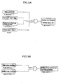
- Fig. 3B conditions required for permitting an operation of the braking force control unit BCU will be described.
- An operation of the braking force control unit BCU is permitted while the driving force is either in the weak creep condition or in the middle creep condition.
- the driving force is not sufficient for keeping the vehicle stationary on a slope having an inclination angle of 5 degrees. Therefore, the driver is forced to depress the brake pedal BP sufficiently before the retaining braking force to obtain sufficient driving force for preventing backward displacement of the vehicle.
- the driving force in the weak creep condition or in the middle creep condition is determined based on a hydraulic pressure command value to a linear solenoid valve of CVT 3, where the engagement the hydraulic pressure of the starting clutch is controlled.
- the weak creep order (F_WCRP) is transmitted when any of the following conditions I) and II) is satisfied.
- the conditions are:
- the weak creep order is transmitted and the driving force is switched to the weak creep condition.
- the above conditions are determined at the driving force decreasing unit DDU.
- the reason for switching the driving force to the weak creep condition is to improve the vehicle's fuel consumption. When on a slope, it is for reminding the driver to forcefully depress the brake pedal BP to prevent backward displacement of the vehicle while the vehicle stops on the slope. When on a flat surface, the driver can stop the vehicle with a weaker braking force because the driving force is weak in the weak creep condition. Therefore, in the weak creep condition, the depression force of the brake pedal BP by the driver is lessened.
- a strong creep order for driving (F_MSCRP) is transmitted when both of the following two conditions I) and II) are satisfied (Fig. 4B).
- the creep diving force is switched to the strong creep condition for driving after the strong creep order for driving is transmitted.
- the strong creep condition is retained if the driving force is not changed to the weak creep condition when the vehicle speed decreases again to 5 km/h (vehicle speed 5 km/h) or if the vehicle speed at 5 km/h or lower is retained after switching to the strong creep condition by releasing the brake pedal BP while being in the weak creep condition.
- the middle creep condition is required.
- the driving force is switched to the middle creep condition.
- a determination of whether or not the driving force is in the weak creep condition, strong creep condition for driving or the middle creep condition, is made based on the hydraulic pressure command value to the starting clutch of CVT 3.
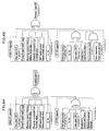
- engine 1 is automatically stopped while the vehicle stops. Conditions for automatically stopping engine 1 will be described. When all the conditions shown in Fig. 5 are satisfied, an engine stop order (F_ENGOFF) is transmitted and engine 1 is automatically stopped.
- the automatic engine stop operation of engine 1 is carried out by the driving motor stopping unit. Therefore, the following automatic engine stop conditions are determined at the driving motor stopping unit. Specifically, the automatic engine stop conditions are determined at FI/MG ECU 4 and CVT ECU 6.
- F_MGSTB becomes 1.
- CVT ECU 6 determines that all the following conditions IX) to XV) are satisfied, F_CVTOK becomes 1.
- the automatic engine stop conditions include conditions required for the weak creep order. In other words, the automatic engine stop conditions are not satisfied as long as the conditions for the weak creep order are not satisfied. Further, in the automatic engine stop conditions, engine 1 is automatically stopped when the vehicle speed is 0 km/h. Meanwhile, in the conditions required for the weak creep order, the driving force is decreased to the weak creep condition when the vehicle speed is 5 km/h. For this reason, the driving motor stopping unit automatically stops engine 1 after the driving force decreasing unit DDU decreases the driving force to the weak creep condition at the vehicle speed of 5 km/h and the vehicle speed falls to 0 km/h.
- the solenoid valves SV are switched to the communicating position for releasing the retained braking force.
- the creep rising condition the driving force has been increased to such an extent that backward displacement of the vehicle on a slope is prevented, taking into consideration the inertial force and the rolling resistance (increasing driving force) of the vehicle. Therefore, even if the actuation of the braking force control unit BCU is released and the braking force is lost, backward displacement of the vehicle is prevented.
- the creep rising condition also includes a condition allowing slight backward displacement of the vehicle, as long as the increasing driving force minimizes the backward displacement of the vehicle.
- the strong creep order (F_SCRP) is transmitted when any of the following two conditions shown in Figs. 7A and 7B is satisfied.
- the first condition required for the strong creep order is that either I) or II) is satisfied (Fig. 7A).
- Conditions I) and IV) are determined at the driving force decreasing unit DDU.
- condition I (1) to (3) of condition I
- condition III (1) to (3) of condition III
- the driving force may be switched to the strong creep condition even if the vehicle displaces in the same direction in which the driver intends to move.
- the vehicle is running.
- the vehicle having the above system is operated in the order of braking, stopping and starting.
- the driving force is decreased from the strong creep condition for driving to the weak creep condition by the driving force decreasing unit DDU, and thereafter engine 1 is stopped by the driving motor stopping unit.
- the positioning switch PSW and the mode switch MSW of the vehicle are not changed from the D range/D mode.
- the braking force control unit BCU comprises a relief valve RV.
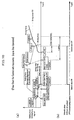
- Fig. 10(a) the processes of increasing and decreasing the driving force of the vehicle are shown in time sequence order.
- a thick line indicates the driving force and a thin line indicates the braking force.
- ON/OFF (shut-off position/communicating position) of the solenoid valves SV is shown.
- the driving force decreasing unit DDU transmits a strong creep order for driving (F_MSCRP) when the driver releases the accelerator pedal (TH [OFF]) while the vehicle is running (vehicle speed > 5 km/h).
- the driving force is then switched to the strong creep condition for driving (F_MSCRPON), which is less than the strong creep condition (F_SCRPON).
- the driving force decreasing unit DDU transmits a weak creep order (F_WCRP) and driving force is switched to the weak creep condition (F_WCRPON).
- F_WCRP weak creep order
- F_WCRPON weak creep condition
- the braking force control unit BCU switches the solenoid valves SV to the shut-off position to retain braking force. Further, the driving motor stopping unit automatically stops engine 1 (F_ENGOFF) and the driving force is lost. Because the driving force is in the weak creep condition before engine 1 is automatically stopped, the driving force falls to zero from a smaller driving force in the weak creep condition, leading to a smaller driving force difference. Further, because the driving force is decreased to the weak creep condition before automatically stopping engine 1, the braking force required for stopping the vehicle may be less than that required in the strong creep condition. In other words, the vehicle can be stopped in the weak creep condition even if depression of the brake pedal BP is reduced less.
- the detected vehicle speed may be 0 km/h even if the vehicle does not stop completely.
- the actual vehicle speed may not be 0 km/h and the vehicle moves at an extremely low speed (the vehicle is in a condition just before stopping).
- the driving motor stopping unit automatically stops engine 1 before the vehicle stops completely (detected vehicle speed is 0 km/h)
- the vehicle does not stop suddenly and the driver can perform a smooth stopping operation without any awkwardness, because of the smaller driving force difference and weaker braking force.
- Engine 1 is automatically stopped for the purposes of improved fuel consumption as well as reducing of exhaust gas.
- the driver then releases the brake pedal BP in order to prepare for restarting the vehicle. If the diver depresses the brake pedal BP more than a preset pressure of the relief valve RV (relief pressure), the relief valve RV actuates upon the driver releasing the brake pedal BP and braking force immediately decreases to the relief pressure. Providing the relief valve RV ensures a smooth starting operation of the vehicle on a slope, even if the driver depresses the brake pedal BP more than is required.
- a preset pressure of the relief valve RV relieve pressure
- Hydraulic oil has been discharged from the oil pressure chamber of the starting clutch at CVT 3 while engine 1 is stopped. Therefore, when engine 1 is actuated and the supply of pressure oil to the starting clutch is initiated, the driving force suddenly rises (sudden rise of the driving force at SC [ON]) due to resistance of a piston enforcing the clutch. Further, a clearance or play exists for the advance stroke of the piston while engine 1 is stopped because hydraulic oil has been discharged. Therefore, the hydraulic pressure command value to the starting clutch does not correspond to the actual hydraulic pressure value; hence the driving force transmission capacity of the starting clutch increases little by little until the oil pressure chamber is filled with hydraulic oil. As a result, the driving force gradually increases, and when the oil pressure chamber is filled with hydraulic oil, the driving force then increases in accordance with the hydraulic pressure command value.
- the braking force control unit BCU instantly releases the braking force retained by the solenoid valves SV during the process of increasing the driving force to the strong condition (F_SCDLY). Even if the braking force is instantly released at this stage, a smooth starting operation of the vehicle is achieved by the increasing driving force because the inertial force and the rolling resistance (increasing driving force) of the vehicle restricts backward displacement.
- the timing at which the release of the braking force is carried out occurs when a certain period of time passes after the supply of pressure oil is initiated (SC [ON]) to the starting clutch at CVT 3.
- the certain time is counted by a creep rising timer.
- a signal creep rising signal F_SCDLY
- F_SCDLY creep rising signal
- the brake switch BSW is OFF, the solenoid valve SV is immediately returned to the communicating position, thereby releasing the braking force.
- the reason for determining the creep rising condition by using the timer is that the hydraulic pressure command value to the starting clutch does not correspond to the actual hydraulic pressure value (driving force transmission capacity). This is because hydraulic oil has been discharged from the oil pressure chamber of the starting clutch while engine 1 is stopped.
- a dashed and dotted extends line downward from "Relief pressure" on the line indicating braking force.
- the dashed and dotted line indicates a situation where the brake fluid pressure is not retained. In this situation, because reduction of the braking force takes place immediately after decreasing the brake pedal load and braking force is quickly lost, a smooth starting operation of the vehicle is not achieved.
- the dashed and dotted line also indicates returned conditions of the brake pedal BP.
- the driving motor stopping unit decreases the driving force before automatically stopping the driving motor, the braking force required for stopping the vehicle is less than that required before decreasing the driving force. Further, the driving force difference upon stopping the driving motor becomes smaller. Therefore, the vehicle stops smoothly without sudden impact, even if the driving motor is stopped before automatically stopping the vehicle.
- the driving motor stopping unit has been described with a vehicle having CVT, however, it may be applicable to other vehicles, such as an automatic transmission-type vehicle with a torque converter.
- a driving motor stopping unit for a vehicle which vehicle allows transmission of driving force from a driving motor to driving wheels irrespective of releasing an accelerator pedal at a certain or lower vehicle speed when a transmission is selected to a driving range, wherein said vehicle is further provided with a driving force decreasing unit which switches the driving force in accordance with depression of a brake pedal such that the driving force is made lower at a depression of the brake pedal than at a release of the brake pedal, and the driving motor is stopped after the driving force is decreased by the driving force decreasing unit.
Landscapes
- Engineering & Computer Science (AREA)
- Transportation (AREA)
- Mechanical Engineering (AREA)
- Chemical & Material Sciences (AREA)
- Combustion & Propulsion (AREA)
- Automation & Control Theory (AREA)
- Control Of Vehicle Engines Or Engines For Specific Uses (AREA)
- Control Of Driving Devices And Active Controlling Of Vehicle (AREA)
- Regulating Braking Force (AREA)
- Hybrid Electric Vehicles (AREA)
- Electric Propulsion And Braking For Vehicles (AREA)
- Output Control And Ontrol Of Special Type Engine (AREA)
- Electrical Control Of Air Or Fuel Supplied To Internal-Combustion Engine (AREA)
Applications Claiming Priority (2)
| Application Number | Priority Date | Filing Date | Title |
|---|---|---|---|
| JP18956799 | 1999-07-02 | ||
| JP18956799A JP3240560B2 (ja) | 1999-07-02 | 1999-07-02 | 原動機停止装置 |
Publications (2)
| Publication Number | Publication Date |
|---|---|
| EP1065091A2 true EP1065091A2 (de) | 2001-01-03 |
| EP1065091A3 EP1065091A3 (de) | 2004-01-02 |
Family
ID=16243505
Family Applications (1)
| Application Number | Title | Priority Date | Filing Date |
|---|---|---|---|
| EP00113918A Withdrawn EP1065091A3 (de) | 1999-07-02 | 2000-06-30 | Vorrichtung zur Steuerung eines Antriebsmotors |
Country Status (4)
| Country | Link |
|---|---|
| US (1) | US6388407B1 (de) |
| EP (1) | EP1065091A3 (de) |
| JP (1) | JP3240560B2 (de) |
| CA (1) | CA2313284C (de) |
Cited By (5)
| Publication number | Priority date | Publication date | Assignee | Title |
|---|---|---|---|---|
| EP1251288A1 (de) * | 2001-04-19 | 2002-10-23 | Transmission Technologies Corporation | Verfahren und Einrichtung zum Betrieb einer Kupplung für ein automatisiertes Schaltgetriebe |
| WO2004091961A1 (de) * | 2003-04-16 | 2004-10-28 | Daimlerchrysler Ag | Verfahren zum betrieb eines kraftfahrzeugs |
| WO2011003848A1 (de) * | 2009-07-10 | 2011-01-13 | Robert Bosch Gmbh | Verfahren zur koordination von zumindest einem antriebsaggregat |
| EP2781393A4 (de) * | 2011-11-14 | 2017-01-18 | Toyota Jidosha Kabushiki Kaisha | Fahrzeug |
| CN112622845A (zh) * | 2020-12-23 | 2021-04-09 | 万向钱潮股份有限公司 | 一种热备用电子驻车制动系统协调控制方法 |
Families Citing this family (15)
| Publication number | Priority date | Publication date | Assignee | Title |
|---|---|---|---|---|
| JP3588091B2 (ja) * | 2002-08-22 | 2004-11-10 | 本田技研工業株式会社 | ハイブリッド車両の油圧制御装置 |
| US7988593B2 (en) * | 2008-02-11 | 2011-08-02 | Caterpillar Inc. | Creep control for motor system |
| JP2010075036A (ja) * | 2008-08-22 | 2010-04-02 | Fuji Heavy Ind Ltd | 電気自動車の制御装置 |
| JP5184406B2 (ja) * | 2009-03-11 | 2013-04-17 | 富士重工業株式会社 | 電気自動車の制御装置 |
| US8801575B1 (en) * | 2009-07-23 | 2014-08-12 | Ryszard Nawrocki | Powered vehicle interlock system |
| JP5516132B2 (ja) * | 2010-06-25 | 2014-06-11 | 株式会社アドヴィックス | 車両の制御装置 |
| US8585543B1 (en) | 2012-11-01 | 2013-11-19 | Caterpillar Inc. | Speed control for a machine with a continuously variable transmission |
| US8545368B1 (en) | 2012-11-01 | 2013-10-01 | Caterpillar Inc. | Regulation of a machine with a continuously variable transmission and service brakes |
| US9169926B2 (en) | 2012-11-01 | 2015-10-27 | Caterpillar Inc. | System and method of operating a machine having a continuously variable transmission |
| US8849527B2 (en) | 2012-11-01 | 2014-09-30 | Caterpillar Inc. | Speed control for a machine with a continuously variable transmission |
| US8795133B2 (en) | 2012-11-01 | 2014-08-05 | Caterpillar Inc. | Event-based retarding in a machine with a continuously variable transmission |
| US9002595B2 (en) | 2012-11-01 | 2015-04-07 | Caterpillar Inc. | Torque and speed control in a machine with continuously variable transmission |
| JP6176197B2 (ja) * | 2014-07-07 | 2017-08-09 | トヨタ自動車株式会社 | 車両の制御装置 |
| US10322688B2 (en) * | 2016-12-30 | 2019-06-18 | Textron Innovations Inc. | Controlling electrical access to a lithium battery on a utility vehicle |
| CN112677939A (zh) * | 2021-01-07 | 2021-04-20 | 广西汽车集团有限公司 | 一种基于触边开关的智能驾驶车的紧急制动装置及方法 |
Family Cites Families (17)
| Publication number | Priority date | Publication date | Assignee | Title |
|---|---|---|---|---|
| JPS60252032A (ja) * | 1984-05-26 | 1985-12-12 | Fuji Heavy Ind Ltd | 電磁式クラツチ付車両の減速制御装置 |
| JPH01115747A (ja) * | 1987-10-30 | 1989-05-09 | Isuzu Motors Ltd | 自動クラッチ制御装置 |
| JPH01115745A (ja) * | 1987-10-30 | 1989-05-09 | Isuzu Motors Ltd | 自動クラッチ制御装置 |
| JPH01244930A (ja) | 1988-03-24 | 1989-09-29 | Fuji Heavy Ind Ltd | 車両用自動クラッチの制御装置 |
| JP2722856B2 (ja) * | 1991-05-30 | 1998-03-09 | 日産自動車株式会社 | 内燃機関のアイドル回転制御装置 |
| JP2741739B2 (ja) * | 1992-08-26 | 1998-04-22 | 本田技研工業株式会社 | 電気自動車の疑似クリープ発生装置 |
| FR2708530B1 (fr) * | 1993-08-03 | 1997-01-24 | Luk Getriebe Systeme Gmbh | Véhicule équipé d'un embrayage automatique. |
| JPH08183368A (ja) * | 1994-12-29 | 1996-07-16 | Suzuki Motor Corp | エンジンの自動始動停止装置 |
| JP3052803B2 (ja) * | 1995-05-19 | 2000-06-19 | トヨタ自動車株式会社 | 動力伝達装置およびその制御方法 |
| JP3284852B2 (ja) * | 1995-10-20 | 2002-05-20 | 日産自動車株式会社 | 無段変速機の変速制御装置 |
| JP3555402B2 (ja) * | 1997-09-01 | 2004-08-18 | 日産自動車株式会社 | 車速制御装置 |
| JP3679228B2 (ja) * | 1997-09-04 | 2005-08-03 | 日野自動車株式会社 | ハイブリッド自動車のエンジン停止方法および装置 |
| JP3645077B2 (ja) | 1997-11-07 | 2005-05-11 | 日野自動車株式会社 | 内燃機関の自動停止装置および自動始動装置 |
| JP3847438B2 (ja) * | 1998-02-03 | 2006-11-22 | 本田技研工業株式会社 | ハイブリッド車両の制御装置 |
| JP3598491B2 (ja) * | 1998-12-25 | 2004-12-08 | 本田技研工業株式会社 | ブレーキ液圧保持装置 |
| JP3196076B2 (ja) * | 1998-12-25 | 2001-08-06 | 本田技研工業株式会社 | 原動機付車両 |
| JP3574997B2 (ja) * | 1999-06-11 | 2004-10-06 | 本田技研工業株式会社 | ブレーキ力制御装置 |
-
1999
- 1999-07-02 JP JP18956799A patent/JP3240560B2/ja not_active Expired - Lifetime
-
2000
- 2000-06-30 EP EP00113918A patent/EP1065091A3/de not_active Withdrawn
- 2000-06-30 CA CA002313284A patent/CA2313284C/en not_active Expired - Fee Related
- 2000-07-03 US US09/610,011 patent/US6388407B1/en not_active Expired - Lifetime
Non-Patent Citations (1)
| Title |
|---|
| None |
Cited By (9)
| Publication number | Priority date | Publication date | Assignee | Title |
|---|---|---|---|---|
| EP1251288A1 (de) * | 2001-04-19 | 2002-10-23 | Transmission Technologies Corporation | Verfahren und Einrichtung zum Betrieb einer Kupplung für ein automatisiertes Schaltgetriebe |
| WO2004091961A1 (de) * | 2003-04-16 | 2004-10-28 | Daimlerchrysler Ag | Verfahren zum betrieb eines kraftfahrzeugs |
| US7585250B2 (en) | 2003-04-16 | 2009-09-08 | Daimler Ag | Method for operating a motor vehicle |
| WO2011003848A1 (de) * | 2009-07-10 | 2011-01-13 | Robert Bosch Gmbh | Verfahren zur koordination von zumindest einem antriebsaggregat |
| CN102470875A (zh) * | 2009-07-10 | 2012-05-23 | 罗伯特·博世有限公司 | 用于对至少一个驱动机组进行协调的方法 |
| CN102470875B (zh) * | 2009-07-10 | 2015-04-08 | 罗伯特·博世有限公司 | 用于对至少一个驱动机组进行协调的方法 |
| US9090242B2 (en) | 2009-07-10 | 2015-07-28 | Robert Bosch Gmbh | Method for coordinating at least one drive unit |
| EP2781393A4 (de) * | 2011-11-14 | 2017-01-18 | Toyota Jidosha Kabushiki Kaisha | Fahrzeug |
| CN112622845A (zh) * | 2020-12-23 | 2021-04-09 | 万向钱潮股份有限公司 | 一种热备用电子驻车制动系统协调控制方法 |
Also Published As
| Publication number | Publication date |
|---|---|
| JP3240560B2 (ja) | 2001-12-17 |
| CA2313284A1 (en) | 2001-01-02 |
| EP1065091A3 (de) | 2004-01-02 |
| US6388407B1 (en) | 2002-05-14 |
| CA2313284C (en) | 2006-03-28 |
| JP2001020776A (ja) | 2001-01-23 |
Similar Documents
| Publication | Publication Date | Title |
|---|---|---|
| US6547344B2 (en) | Braking apparatus for vehicles | |
| US6533081B2 (en) | Brake fluid pressure retaining apparatus | |
| US6346064B1 (en) | Driving force control unit for vehicles | |
| US6338398B1 (en) | Vehicle with braking force retaining unit | |
| US6370466B1 (en) | Braking force retaining unit | |
| US6388407B1 (en) | Apparatus for controlling a driving motor | |
| US6415897B1 (en) | Brake fluid pressure retaining unit | |
| EP1616763B1 (de) | Fahrzeug mit einer Einheit zur Abschaltung des Antriebsmotors. | |
| US7484816B2 (en) | Vehicle control apparatus | |
| US6358182B1 (en) | Driving force control unit for vehicles | |
| US6336689B1 (en) | Brake fluid pressure retaining unit | |
| US6328672B1 (en) | Driving force control unit for vehicle | |
| JP3642507B2 (ja) | 車両の駆動力制御装置 | |
| JP3967850B2 (ja) | ブレーキ力保持装置付きの車両 | |
| EP1065115B1 (de) | Antriebskraftsteuerung eines Fahrzeugs | |
| JP2001163197A (ja) | ブレーキ力保持装置付車両 | |
| JP2000272485A (ja) | ブレーキ液圧保持装置 | |
| JP2001047987A (ja) | ブレーキ力保持装置 | |
| JP2000313320A (ja) | ブレーキ力制御装置 |
Legal Events
| Date | Code | Title | Description |
|---|---|---|---|
| PUAI | Public reference made under article 153(3) epc to a published international application that has entered the european phase |
Free format text: ORIGINAL CODE: 0009012 |
|
| AK | Designated contracting states |
Kind code of ref document: A2 Designated state(s): AT BE CH CY DE DK ES FI FR GB GR IE IT LI LU MC NL PT SE |
|
| AX | Request for extension of the european patent |
Free format text: AL;LT;LV;MK;RO;SI |
|
| PUAL | Search report despatched |
Free format text: ORIGINAL CODE: 0009013 |
|
| AK | Designated contracting states |
Kind code of ref document: A3 Designated state(s): AT BE CH CY DE DK ES FI FR GB GR IE IT LI LU MC NL PT SE |
|
| AX | Request for extension of the european patent |
Extension state: AL LT LV MK RO SI |
|
| 17P | Request for examination filed |
Effective date: 20040210 |
|
| 17Q | First examination report despatched |
Effective date: 20040518 |
|
| AKX | Designation fees paid |
Designated state(s): DE FR GB |
|
| STAA | Information on the status of an ep patent application or granted ep patent |
Free format text: STATUS: THE APPLICATION IS DEEMED TO BE WITHDRAWN |
|
| 18D | Application deemed to be withdrawn |
Effective date: 20050316 |