EP1065305A2 - Dispositif de tension pour le déroulement des fils de chaíne de fond dans les métiers pour tissu éponge du type à toile mobile - Google Patents
Dispositif de tension pour le déroulement des fils de chaíne de fond dans les métiers pour tissu éponge du type à toile mobile Download PDFInfo
- Publication number
- EP1065305A2 EP1065305A2 EP00113260A EP00113260A EP1065305A2 EP 1065305 A2 EP1065305 A2 EP 1065305A2 EP 00113260 A EP00113260 A EP 00113260A EP 00113260 A EP00113260 A EP 00113260A EP 1065305 A2 EP1065305 A2 EP 1065305A2
- Authority
- EP
- European Patent Office
- Prior art keywords
- ground warp
- tension
- swing levers
- movable type
- type pile
- Prior art date
- Legal status (The legal status is an assumption and is not a legal conclusion. Google has not performed a legal analysis and makes no representation as to the accuracy of the status listed.)
- Withdrawn
Links
- 239000004744 fabric Substances 0.000 title claims abstract description 60
- 230000033001 locomotion Effects 0.000 claims abstract description 68
- 230000007246 mechanism Effects 0.000 claims description 15
- 230000010354 integration Effects 0.000 claims description 7
- 230000001360 synchronised effect Effects 0.000 claims description 6
- 238000006243 chemical reaction Methods 0.000 claims description 4
- 235000014676 Phragmites communis Nutrition 0.000 description 2
- 238000010009 beating Methods 0.000 description 2
- 238000009941 weaving Methods 0.000 description 2
- 238000004804 winding Methods 0.000 description 2
- 238000006073 displacement reaction Methods 0.000 description 1
- 230000000694 effects Effects 0.000 description 1
- 239000000463 material Substances 0.000 description 1
Images


Classifications
-
- D—TEXTILES; PAPER
- D03—WEAVING
- D03D—WOVEN FABRICS; METHODS OF WEAVING; LOOMS
- D03D39/00—Pile-fabric looms
- D03D39/22—Terry looms
- D03D39/223—Cloth control
-
- D—TEXTILES; PAPER
- D03—WEAVING
- D03D—WOVEN FABRICS; METHODS OF WEAVING; LOOMS
- D03D49/00—Details or constructional features not specially adapted for looms of a particular type
- D03D49/04—Control of the tension in warp or cloth
- D03D49/12—Controlling warp tension by means other than let-off mechanisms
Definitions
- the invention relates to a device for applying tension onto a ground warp yarns in a cloth movable type pile loom by the displacement of a ground warp tension roller.
- a cloth movable type pile loom is provided with a terry motion.
- the terry motion moves a ground warp tension roller in the same direction as a woven cloth so as to move a cloth fell of a woven cloth back and forth.
- the terry motion is associated with a supporting mechanism of a ground warp tension roller to move the ground warp tension roller back and forth.
- the ground warp tension roller is naturally biased in the direction to apply tension to the ground warp yarns.
- Fig. 1 shows a schematic view of a ground warp let-off tension device 1 of a conventional typical cloth movable type pile loom as disclosed in Japanese Patent Laid-Open Publication No. 9-111597.
- ground warp yarns 2 are unwound from a ground warp let-off beam 3, and they contact a ground warp tension roller 4, then they form a shedding 8 by a vertical movement of heddles 5, and finally they reach a cloth fell 7 of a woven cloth 6.
- pile warp yarns 9 are unwound from a pile warp let-off beam 10 and contact a pile warp tension roller 11, then they reach the cloth fell cloth fell 7 of the woven cloth 6.
- a weft yarn 12 inserted in the position of the shedding 8 is beaten up against the cloth fell 7 by a reed 13 to form the woven cloth 6, then the woven cloth 6 passes through a cloth moving roller 14 and is wound around a cloth winding roller 15.
- the terry motion 16 comprises brackets 18, 19 respectively attached to the right and left frames 17, L-shaped terry motion levers 20, 21 respectively rotatably supported by shafts 23, 24 relative to the brackets 18, 19, and links 22, shafts 25, 26 for connecting the end portions of the terry motion levers 20, 21.
- the terry motion levers 20 are biased clockwise by extension springs 27, and they are supported by a cam 28 and a cam roller 30 that contacts the outer periphery of the cam 28 so as to swing back and forth in synchronization with the rotation of the main shaft 32 of the loom.
- the cam 28 is integrated with a camshaft 29 and is driven while interlocked with the rotation of the main shaft 32 of the loom.
- the cam roller 30 is rotatably supported by the roller shaft 31 of the terry motion levers 20.
- the swingably motion of the terry motion levers 20 is transmitted to each one end of a pair of right and left swing levers 36 by way of a shaft 34, interlocking links 33 and a shaft 35.
- the swing levers 36 are swingably supported by a bracket 37 and a shaft 38 respectively fixed to the frames 17, and they swingably support a pair of right and left levers 41 by an intermediate shaft 39.
- the pair of right and left levers 41 are connected to and integrated with each other by a roller shaft 40 serving as a shaft fully extending to the right and left thereof (hereinafter referred to as simply through shaft) whereby the ground warp tension roller 4 is rotatably supported by the levers 41 at respective one ends while they are biased by an extension spring 42 in the direction to apply tension to the ground warp yarns 2 by way of the ground warp tension roller 4 at the respective other ends.
- a biasing force of the extension spring 42 acts on the right and left sides of the ground warp tension roller 4 uniformly to the right and left so as to apply a uniform tension to the ground warp yarns 2.
- the cam 28 is synchronized with the rotation of the main shaft 32 to swing each terry motion levers 20 back and forth. Accordingly, respective terry motion levers 20 move the cloth moving roller 14 back and forth by way of respective links 22 and levers 21 while they move the ground warp tension roller 4 back and forth by way of the respective interlocking links 33 and swing levers 36. As a result, when the ground warp yarns 2 and woven cloth 6 are moved back and forth, the cloth fell 7 is set to a first pick position and loose pick position corresponding to the weaving texture.
- the loom As a loom operates at high speed and becomes large in width lately, the loom is required to increase its rigidity, so that respective components of the loom become heavy, Accordingly, a load applied to the terry motion 16 increases so that there occurred a breakage in the terry motion 16. Further, since the extension spring 42 is repeatedly moved back and forth when the device is moved back and forth, a desired elasticity is not obtained by the fatigue of the extension spring 42 so that the extension spring 42 has been broken on an early stage. Since the roller shaft 40 of the ground warp tension roller 4 is a through shaft for connecting and integrating the pair of right and left levers 41 with each other, and it is heavy so that inertia of the ground warp tension roller 4 becomes large. Accordingly, it is difficult for the ground warp tension roller 4 to move quickly to follow the change of tension of the ground warp yarns 2 so as to be kept constant.
- the cloth movable type pile loom capable of moving a ground warp tension roller back and forth by a terry motion 16 comprising a pair of first right and left swing levers 43 each rotatably supporting the ground warp tension roller 4, at least one of right and left swing levers 43 connected to the terry motion 16, a pair of second right and left swing levers 45 each being swingably supported by right and left frames 17 and rotatably connected to the first swing levers 43, and tension application means 48 for applying a biasing force to the second swing levers 45 in the turning direction thereof to press ground warp yarns 2 by way of the ground warp tension roller 4.
- the pair of second right and left swing levers 45 are connected to and integrated with each other by a connection and integration member and the pair of second right and left swing levers 45 are swingably supported by the right and left frames 17 by way of a fulcrum shaft 46 which are the connection and integration members.
- the tension application means 48 is formed of an extension spring 49 for passively applying the biasing force to the second swing levers 45 in the turning direction thereof by elasticity of the extension spring 49 and the tension application means 48 comprise motion conversion mechanisms (53, 54, 55, 56, 57), and the tension application means 48 are synchronized with the rotation of the main shaft 32 of the loom to positively apply a reciprocation motion to the second swing levers 45.
- the second swing levers swingably support the first swing levers which are driven by the terry motion, however, the second swing levers, the second shaft serving as the fulcrum shaft of the swing motion of the second swing levers, and the first shaft for connecting between the first and second swing levers are not driven by the terry motion.
- the roller shaft and the shaft 35 need not be formed of a through shaft, and the terry motion need not drive a heavy through shaft. Accordingly, the invention can reduce the load applied to the terry motion and prevent the terry motion from being broken in advance owing to the increase of the load compared with the prior art.
- the first shaft need not be formed of a through shaft. Accordingly, a member to be swung by the tension spring can dispense with a heavy through shaft to reduce inertia.
- the tension application means is formed of a spring, the spring allows the ground warp tension load to quickly respond to the change of tension of the ground warp yarns to follow them. More still further, since the second swing levers are not moved back and forth, the spring is not deformed back and forth to solve the problem of fatigue caused by the deformation, thereby reducing the breakage of the spring. Even if the tension application means is formed is positively formed of an easing mechanism, it is possible to achieve easy motion that is accurately synchronized with the rotation of the main shaft, because the second swing levers do not move back and forth.
- a ground warp let-off tension device 1 of a cloth movable type pile loom according to a first embodiment of the invention is first described with reference to Figs. 2 and 3.
- a part of the configuration of the first embodiment is the same as that of the conventional one, and hence the same components of the invention as those of the prior art are denoted by the same reference numerals.
- ground warp yarns 2 are unwound from a ground warp let-off beam 3, and contact a ground warp tension roller 4, then they form a shedding 8 by a vertical movement of heddles 5, and finally they reach a cloth fell 7 of a woven cloth 6.
- pile warp yarns 9 are unwound from a pile warp let-off beam 10 and contacts a pile warp tension roller 11, then they reach the cloth fell 7 of the woven cloth 6.
- a weft yarn12 inserted inside the shedding 8 in the position of the shedding 8 is beaten up against the cloth fell 7 by a reed 13, and it forms the woven cloth 6, then the woven cloth 6 passes through a cloth moving roller 14 and is wound around a cloth winding roller 15.
- the terry motion 16 comprises brackets 18, 19 respectively attached to the right and left frames 17, L-shaped terry motion levers 20, 21 respectively rotatably supported by shafts 23, 24 relative to the brackets 18, 19, links 22, and shafts 25, 26 respectively connecting the free ends of terry motion levers 20, 21.
- the terry motion levers 20 are biased clockwise by extension springs 27, and they are supported by a cam 28 and a cam roller 30 that contacts the outer periphery of the cam 28 so as to swing back and forth in synchronization with the rotation of the main shaft 32 of the loom.
- the cam 28 is integrated with a camshaft 29 and is driven while interlocked with the rotation of the main shaft 32 of the loom.
- the cam roller 30 is rotatably supported by the roller shaft 31 of the terry motion levers 20.
- the swingable motion of the terry motion levers 20 is transmitted to respective one ends of a pair of first right and left swing levers 43 by way of a pair of right and left interlocking links 33 and a shaft 35.
- the first swing levers 43 rotatably support the ground warp tension roller 4 by the intermediate roller shaft 40 and connected to respective one ends of a pair of second right and left swing levers 45 by a first shaft 44 at respective other ends.
- the pair of second right and left swing levers 45 are swingably supported by a second shaft 46 serving as a fulcrum shaft relative to a bracket 47 fixed to the right and left frames 17, and they are connected to and integrated with each other by the second shaft 46 serving as a connection and integration member, and they are also engaged with the right and left frames 17 by an extension spring 49 serving as tension application means 48. Since the second right and left swing levers 45 are connected to and integrated with each other at the right and left, the biasing force of the extension spring 49 equally acts on the second right and left swing levers 45.
- both the roller shaft 40 and first shaft 44 dispense with a through shaft extending to the right and left thereof and forming a heavy item.
- two first shafts 44 are provided separately at the right and left, namely, at the side of the respective right and left levers 45 to lighten them as much as possible. Accordingly, it is possible to reduce inertia which prevents the ground warp tension roller 4 from moving in response to the change of tension of the ground warp yarns 2, so that the ground warp tension roller 4 can respond quickly to keep tension of the ground warp constant.
- first shaft 44 is formed of a through shaft, it is advantageous that a load applied to the terry motion 16 is reduced.
- the first shaft 44 may be used as the connection and integration member of the second right and left swing levers 45 instead of the second shaft 46. In the latter case, although the characteristic of the ground warp tension roller 4 following the change of tension of the ground warp yarns 2 are degraded, the effect for reducing a load applied to the terry motion 16 is equal.
- a tension detector 50 such as a load cell is interposed in the end of the extension spring 49.
- the tension detector 50 indirectly measures tension of the ground warp yarns 2 from stress of the extension spring 49 and sends out a signal proportional to tension of the ground warp yarns 2 to a let-off motion 51.
- the let-off motion 51 adjusts a rotating speed of a let-off motor 52 on the basis of the difference between a target tension of the ground warp yarns 2 and the detected tension, then it rotates the ground warp let-off beam 3 in the let-off or unwinding direction so as to unwind the ground warp yarns 2 while keeping the ground warp yarns 2 at the target tension.
- the terry motion 16 moves the woven cloth 6, the cloth fell 7 thereof and the ground warp tension roller 4 backward, i.e., in the direction of the ground warp let-off beam 3 immediately before beating up for forming the pile, as shown in Fig. 3, while moving them in the opposite direction after beating up for forming a pile, then the woven cloth 6, the cloth fell 7 thereof and the ground warp tension roller 4 are returned to the original positions as shown in Fig. 2.
- the first swing levers 43 swing about the first shaft 44 while the ground warp tension roller 4 moves back and forth.
- the second right and left swing levers 45 are not directly driven by the swinging motion of the first swing levers 43 while the first swing levers 43 swing back and forth so they do not respond to the back and forth motion of the terry motion 16.
- the extension spring 49 of the tension application means 48 is not interlocked with the motion of the terry motion 16 but passively respond only to the change of tension of the ground warp yarns 2 to push the ground warp yarns 2 in the extension direction by way of the ground warp tension roller 4 so as to apply necessary tension to the ground warp yarns 2.
- the let-off motion 51 increases the rotating speed of the let-off motor 52 to unwind the ground warp yarns 2 per unit of time so as to allow its tension to approach a target tension
- a ground warp let-off tension device of a cloth movable type pile loom according to a second embodiment of the invention is described with reference to Fig. 4.
- interlocking links 33 are positioned downward.
- the interlocking links 33 connect between the lower ends of terry motion levers 20 and first swing levers 43. Accordingly, the terry motion levers 20 are formed of respectively T-shaped levers.
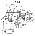
- a ground warp let-off tension device of a cloth movable type pile loom according to a third embodiment of the invention is described with reference to Fig. 5
- a tension detector 50 such as a load cell is not fixed to the extension spring 49 as made in the mentioned embodiment but fixed to a bracket 47, and serves as a connection and integration member of a pair of second right and left swing levers 45.
- the tension detector 50 indirectly measures tension of the ground warp yarns 2 from a load applied to a second shaft 46 serving as a fulcrum shaft.
- Tension application means 48 comprises, instead of the extension spring 49 of the first embodiment shown in Figs. 2 and 3, an easing shaft 53 that is interlocked with the rotation of a main shaft 32, a wheel 54 integrated with the easing shaft 53, an eccentric pin 55 attached to the wheel 54, and rods 57 for connecting between the eccentric pin 55 and a pin 56 of the second swing levers 45.
- the tension application means 48 positively adjust the pressing of the ground warp yarns 2 to set tension of the ground warp yarns 2 to the optimum value in accordance with the angle of rotation of the main shaft 32.
- the tension application means 48 shown in Fig. 5 is a so-called positive easing mechanism by a motion changing mechanism between the rotating and reciprocating motions, and it may be configured by the other known motion changing mechanism.
- the tension application means 48 formed of the extension spring 49 as shown in Figs. 2, 3 and 4 is a so-called passive easing mechanism.
- the terry motion 16 is described as a premise according to the invention, the configuration of the terry motion 16 is not limited to those as illustrated in Figs. 2 to 5 but may be configured by other known mechanism, e.g., a combination of a crank mechanism and a link mechanism. Further, the terry motion 16 may be provided with a the pile warp tension roller 11 which moves back and forth like the ground warp tension roller 4.
Landscapes
- Engineering & Computer Science (AREA)
- Textile Engineering (AREA)
- Looms (AREA)
Applications Claiming Priority (2)
| Application Number | Priority Date | Filing Date | Title |
|---|---|---|---|
| JP18158599 | 1999-06-28 | ||
| JP18158599A JP3552595B2 (ja) | 1999-06-28 | 1999-06-28 | 布移動方式のパイル織機の地経糸送り出しテンション装置 |
Publications (2)
| Publication Number | Publication Date |
|---|---|
| EP1065305A2 true EP1065305A2 (fr) | 2001-01-03 |
| EP1065305A3 EP1065305A3 (fr) | 2002-08-21 |
Family
ID=16103392
Family Applications (1)
| Application Number | Title | Priority Date | Filing Date |
|---|---|---|---|
| EP00113260A Withdrawn EP1065305A3 (fr) | 1999-06-28 | 2000-06-21 | Dispositif de tension pour le déroulement des fils de chaíne de fond dans les métiers pour tissu éponge du type à toile mobile |
Country Status (3)
| Country | Link |
|---|---|
| US (1) | US6230754B1 (fr) |
| EP (1) | EP1065305A3 (fr) |
| JP (1) | JP3552595B2 (fr) |
Cited By (1)
| Publication number | Priority date | Publication date | Assignee | Title |
|---|---|---|---|---|
| EP1621654A3 (fr) * | 2004-07-28 | 2007-06-06 | Tsudakoma Kogyo Kabushiki Kaisha | Système d'entraînement des membres de formation de boucles dans un métier pour tissu éponge du type à toile mobile |
Families Citing this family (5)
| Publication number | Priority date | Publication date | Assignee | Title |
|---|---|---|---|---|
| DE50205747D1 (de) * | 2001-11-16 | 2006-04-13 | Sultex Ag Rueti | Messvorrichtung zur Messung der Gewebespannung in einer Webmaschine und Webmaschine mit einer derartigen Messvorrichtung |
| JP2004169227A (ja) * | 2002-11-21 | 2004-06-17 | Tsudakoma Corp | パイル織機の制御方法 |
| JP2006336160A (ja) * | 2005-06-03 | 2006-12-14 | Tsudakoma Corp | 布移動式パイル織機におけるテリーモーション部材の駆動機構 |
| CN105177826A (zh) * | 2015-09-11 | 2015-12-23 | 湖州乐而达纺织有限公司 | 一种纺织机用进线装置 |
| CN112680871A (zh) * | 2020-12-19 | 2021-04-20 | 江苏莱纳多智能装备有限公司 | 一种布动式毛巾机双后梁机构 |
Family Cites Families (10)
| Publication number | Priority date | Publication date | Assignee | Title |
|---|---|---|---|---|
| CH445405A (de) * | 1965-10-29 | 1967-10-15 | Sulzer Ag | Webmaschine |
| CH552693A (de) * | 1972-05-23 | 1974-08-15 | Sulzer Ag | Webmaschine zur herstellung von frottiergewebe. |
| CH646472A5 (de) * | 1980-08-26 | 1984-11-30 | Saurer Ag Adolph | Einrichtung zum spannen der kettfadenscharen einer webmaschine. |
| JPH03124847A (ja) * | 1989-10-04 | 1991-05-28 | Nissan Motor Co Ltd | 織機の経糸張力調整装置 |
| DE4310840C1 (de) * | 1993-04-02 | 1994-01-13 | Dornier Gmbh Lindauer | Verfahren und Vorrichtung zur Beeinflussung der Zugspannung in einer Polkettfadenschar beim Herstellen von Frottiergewebe auf Webmaschinen |
| DE19530222C1 (de) * | 1995-08-17 | 1996-06-05 | Dornier Gmbh Lindauer | Steuersystem für die Polkette zur Herstellung von Frottiergewebe auf Webmaschinen |
| DE19530333C2 (de) * | 1995-08-17 | 1997-08-28 | Univ Eberhard Karls | Amplifikation von Pilzzellen-DNA sowie Verfahren zum Nachweisen von Pilzzellen in klinischem Material |
| DE19537277C1 (de) * | 1995-10-06 | 1996-08-08 | Dornier Gmbh Lindauer | Frottierwebmaschine mit einer Florhöhenverstelleinrichtung |
| JPH10331053A (ja) * | 1997-05-30 | 1998-12-15 | Tsudakoma Corp | パイル形成装置 |
| JPH1121743A (ja) * | 1997-07-07 | 1999-01-26 | Tsudakoma Corp | パイル形成装置 |
-
1999
- 1999-06-28 JP JP18158599A patent/JP3552595B2/ja not_active Expired - Fee Related
-
2000
- 2000-06-21 EP EP00113260A patent/EP1065305A3/fr not_active Withdrawn
- 2000-06-27 US US09/604,656 patent/US6230754B1/en not_active Expired - Fee Related
Cited By (1)
| Publication number | Priority date | Publication date | Assignee | Title |
|---|---|---|---|---|
| EP1621654A3 (fr) * | 2004-07-28 | 2007-06-06 | Tsudakoma Kogyo Kabushiki Kaisha | Système d'entraînement des membres de formation de boucles dans un métier pour tissu éponge du type à toile mobile |
Also Published As
| Publication number | Publication date |
|---|---|
| US6230754B1 (en) | 2001-05-15 |
| JP2001011752A (ja) | 2001-01-16 |
| EP1065305A3 (fr) | 2002-08-21 |
| JP3552595B2 (ja) | 2004-08-11 |
Similar Documents
| Publication | Publication Date | Title |
|---|---|---|
| JPH0241439A (ja) | サッカー織機 | |
| EP2194176B1 (fr) | Métier pour tissu éponge doté d'un ajusteur de tension de la chaîne de poil | |
| US6230754B1 (en) | Ground warp let-off tension device of a cloth movable type terry pile loom | |
| US5722465A (en) | Mechanism for adjusting the terry pile height | |
| KR20050086363A (ko) | 직기의 송출 장치 | |
| US2639732A (en) | Weaving machinery and control | |
| EP3121320B1 (fr) | Dispositif de réglage de la tension de la pile des fils de chaîne dans un métier à tisser à tissu éponge | |
| US6098670A (en) | Apparatus for tensioning warp threads for a weaving machine and a weaving machine with an apparatus of this kind | |
| JP4249036B2 (ja) | 織機の送出装置 | |
| JP2986738B2 (ja) | 織機でタオル織地を製造するためのパイルたて糸の制御装置 | |
| US4494578A (en) | Weft beat-up mechanism for looms | |
| JP3543444B2 (ja) | 織機のプレスローラ接離装置 | |
| JP2006037289A (ja) | 布移動式パイル織機におけるテリーモーション部材の駆動機構 | |
| EP0458754B1 (fr) | Dispositif pour tendre les fils de chaîne dans un métier à tisser | |
| JP5507951B2 (ja) | 織り機 | |
| EP1710333A2 (fr) | Dispositif d'entraînement des membres de formation de boucles dans un métier pour tissu éponge du type à toile mobile | |
| JPH11172552A (ja) | 布移動式パイル織機の経糸張力補正方法 | |
| JPH0790750A (ja) | パイル織機におけるパイル形成装置 | |
| EP1033427B1 (fr) | Support de tissu réglable pour métiers à tisser | |
| US2722950A (en) | Looms | |
| US5000230A (en) | Loom sley movement with a toggle joint | |
| JP3377166B2 (ja) | パイル形成装置 | |
| JP2623666B2 (ja) | 織機における織段発生防止装置 | |
| EP1031652A2 (fr) | Dispositif de tension de la foule avec suspension progressive pour métiers à tisser | |
| US4478257A (en) | Device for regulating the tension of warp threads in a weaving loom |
Legal Events
| Date | Code | Title | Description |
|---|---|---|---|
| PUAI | Public reference made under article 153(3) epc to a published international application that has entered the european phase |
Free format text: ORIGINAL CODE: 0009012 |
|
| AK | Designated contracting states |
Kind code of ref document: A2 Designated state(s): AT BE CH CY DE DK ES FI FR GB GR IE IT LI LU MC NL PT SE |
|
| AX | Request for extension of the european patent |
Free format text: AL;LT;LV;MK;RO;SI |
|
| PUAL | Search report despatched |
Free format text: ORIGINAL CODE: 0009013 |
|
| AK | Designated contracting states |
Kind code of ref document: A3 Designated state(s): AT BE CH CY DE DK ES FI FR GB GR IE IT LI LU MC NL PT SE |
|
| AX | Request for extension of the european patent |
Free format text: AL;LT;LV;MK;RO;SI |
|
| 17P | Request for examination filed |
Effective date: 20021115 |
|
| AKX | Designation fees paid |
Designated state(s): BE CH DE FR IT LI |
|
| 17Q | First examination report despatched |
Effective date: 20050414 |
|
| STAA | Information on the status of an ep patent application or granted ep patent |
Free format text: STATUS: THE APPLICATION IS DEEMED TO BE WITHDRAWN |
|
| 18D | Application deemed to be withdrawn |
Effective date: 20050825 |