EP1065335B1 - Système de verrouillage électromécanique - Google Patents
Système de verrouillage électromécanique Download PDFInfo
- Publication number
- EP1065335B1 EP1065335B1 EP00113546A EP00113546A EP1065335B1 EP 1065335 B1 EP1065335 B1 EP 1065335B1 EP 00113546 A EP00113546 A EP 00113546A EP 00113546 A EP00113546 A EP 00113546A EP 1065335 B1 EP1065335 B1 EP 1065335B1
- Authority
- EP
- European Patent Office
- Prior art keywords
- key
- lock
- coupling
- accordance
- cylindrical lock
- Prior art date
- Legal status (The legal status is an assumption and is not a legal conclusion. Google has not performed a legal analysis and makes no representation as to the accuracy of the status listed.)
- Expired - Lifetime
Links
- 230000008878 coupling Effects 0.000 claims abstract description 26
- 238000010168 coupling process Methods 0.000 claims abstract description 26
- 238000005859 coupling reaction Methods 0.000 claims abstract description 26
- 230000009471 action Effects 0.000 claims description 2
- 230000008901 benefit Effects 0.000 description 6
- 238000013475 authorization Methods 0.000 description 4
- 238000009434 installation Methods 0.000 description 4
- 238000012545 processing Methods 0.000 description 3
- 230000008054 signal transmission Effects 0.000 description 3
- 230000005540 biological transmission Effects 0.000 description 2
- 238000011156 evaluation Methods 0.000 description 2
- 238000000034 method Methods 0.000 description 2
- 230000008569 process Effects 0.000 description 2
- 230000000712 assembly Effects 0.000 description 1
- 238000000429 assembly Methods 0.000 description 1
- 230000008859 change Effects 0.000 description 1
- 238000004891 communication Methods 0.000 description 1
- 238000013461 design Methods 0.000 description 1
- 230000000694 effects Effects 0.000 description 1
- 230000007246 mechanism Effects 0.000 description 1
- 230000008672 reprogramming Effects 0.000 description 1
- 230000000284 resting effect Effects 0.000 description 1
Images


Classifications
-
- E—FIXED CONSTRUCTIONS
- E05—LOCKS; KEYS; WINDOW OR DOOR FITTINGS; SAFES
- E05B—LOCKS; ACCESSORIES THEREFOR; HANDCUFFS
- E05B47/00—Operating or controlling locks or other fastening devices by electric or magnetic means
- E05B47/06—Controlling mechanically-operated bolts by electro-magnetically-operated detents
- E05B47/0611—Cylinder locks with electromagnetic control
- E05B47/0638—Cylinder locks with electromagnetic control by disconnecting the rotor
- E05B47/0642—Cylinder locks with electromagnetic control by disconnecting the rotor axially, i.e. with an axially disengaging coupling element
-
- E—FIXED CONSTRUCTIONS
- E05—LOCKS; KEYS; WINDOW OR DOOR FITTINGS; SAFES
- E05B—LOCKS; ACCESSORIES THEREFOR; HANDCUFFS
- E05B47/00—Operating or controlling locks or other fastening devices by electric or magnetic means
- E05B47/06—Controlling mechanically-operated bolts by electro-magnetically-operated detents
- E05B47/0611—Cylinder locks with electromagnetic control
- E05B47/0615—Cylinder locks with electromagnetic control operated by handles, e.g. by knobs
-
- E—FIXED CONSTRUCTIONS
- E05—LOCKS; KEYS; WINDOW OR DOOR FITTINGS; SAFES
- E05B—LOCKS; ACCESSORIES THEREFOR; HANDCUFFS
- E05B47/00—Operating or controlling locks or other fastening devices by electric or magnetic means
- E05B47/0001—Operating or controlling locks or other fastening devices by electric or magnetic means with electric actuators; Constructional features thereof
- E05B47/0002—Operating or controlling locks or other fastening devices by electric or magnetic means with electric actuators; Constructional features thereof with electromagnets
Definitions
- the invention relates to an electromechanical cylinder lock, in particular for locking systems, with a cylinder housing, which is provided with two opposing receptacles and in the first recording a key operated with a lock core for rotating a locking nose is rotatably mounted, which actuates the locking bolt.
- EP-A-0 588 209 describes a cylinder lock in which the electromagnetic clutch is arranged in a rotary knob. On the opposite side is also a knob available, which is unlocked by a key. This knob can be easily forcibly operated. From WO-A-99/18310 it is known to generate the power for electrical control by an internal generator.
- the invention has for its object to provide a locking system and in particular an electromechanical cylinder lock for a locking system that is safe to use and can be installed without additional effort.
- an electrically actuated clutch is arranged, which switches due to an electrical switching signal and causes a rotationally fixed connection between the locking lug and the lock core to a rotation of the locking lug by the key permit, wherein the clutch comprises a coupling body which is rotatably connected to the locking lug, and a Kupplungsmit luxury, the is provided along the circumference asymmetrically arranged projections which engage in the tightened position of the coupling in only one angular position relative to the key in corresponding recesses of the coupling body.
- This key and locking lug are when pressing the lock in a defined angular position to each other to allow a safe closing.
- the clutch allows at mechanically matching key in the idle state, a free rotation of the lock core. This has the advantage that no force can be exerted on the actual closing mechanism when the lock is not released. Damage caused by incorrect operation or unauthorized intervention can thus be largely avoided.
- the clutch may also be useful if the clutch is held by spring means in the idle state. It is advantageous if the clutch is de-energized at rest. As a result, the power consumption can be significantly reduced because a lock is usually in the idle state and only for a short time, namely to open the door, is actuated.
- the coupling may for example comprise an electromagnet.
- Such an electromagnetic clutch is relatively simple, robust and can be easily and precisely controlled.
- the electrical switching signal is generated, is basically arbitrary.
- external electronic control units can be provided for switching the clutch.
- an assembly that is located outside the cylinder lock.
- the electrically actuated clutch is rotatably mounted in the second receptacle and is connected via at least one slip ring contact with the externally arranged electronic control.
- the electronic control may for example comprise a code lock, so that after input of the access code, the electrical switching signal is generated.
- the electrical switching signal is effected by an electronic control comprising an antenna which cooperates with a passive transponder system in the key.
- the electrical switching signal is effected by an electronic control having a receiver unit which cooperates with a transmitter unit in the key.
- the antenna for the transponder system or for the receiver unit may be integrated in the front end face of the stationary cylinder housing. It is expedient if the key has a key handle with a section in which the transponder or the transmitting antenna is integrated and which has a small distance to the front end face of the cylinder housing in the inserted position. These measures generate particularly short signal transmission paths, which also allow the use of small antennas with minimal transmission power.
- a manually operable knob which cooperates with the locking lug. This keeps the door open from the inside, even if it is locked from the outside.
- the electronic control is at least partially disposed in the knob.
- This has the advantage that the entire electromechanical locking system is arranged in or on the cylinder housing, which can be installed in a conventional manner.
- the electronic control is connected via at least one slip ring contact with an external power source. But it can also be provided that the electronic control powered by a battery located in the knob. This has the advantage that no connection lines from the lock to a power source are required. Then all necessary assemblies are combined in a cylinder lock, which can be used in any door. It is particularly expedient if the cylinder housing has standardized or standardized dimensions.
- At least one switching means may be provided in the cylinder housing, which is operable by the mechanically matching key to turn on the electronic control.
- the switching means may turn on the electronic control, for example, for a predeterminable time.
- the electronic control is connected via at least one slip ring contact with a central data processing system.
- the reprogramming of access codes or the like can of course also be done without a central data processing system. It is basically possible to provide the electronic control, for example in the knob with appropriate interfaces that allow a change in access permissions.
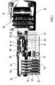
- the cylinder lock shown in the drawing has a cylinder housing 11 with a first and a second opposing receptacle 12 and 13, respectively.
- a locking core 14 is rotatably mounted, which can be actuated by a key (not shown).
- the lock core has for this purpose a plurality of locking pins 15, whose parting plane are aligned with a mechanically matching key so that a rotation is possible.
- the mechanical part therefore includes a mechanical closure over, for example, a plurality of locking pins, which can be unlocked with a mechanically matching key.
- the operation and structure corresponds to a conventional safety lock and therefore requires no further explanation.
- an electrically actuated coupling 16 is provided which can be switched via an electrical signal and then allows rotation of the locking lug 17 by the lock core 14.
- the arrangement is such that the coupling body 18 is rotatably mounted in the second receptacle 13 and rotationally fixed to the locking lug 17 is in communication. By rotating the clutch can thus be done twisting the locking lug to unlock the door or the like.
- a knob 19 is arranged, which cooperates with the locking lug 17.
- the knob 19 is rotatably connected to the coupling body 18, so that when turning the knob, the locking lug is rotated by means of the coupling body 18. The door can thus be unlocked.
- an electronic control 20 is arranged, which is powered by a grid-independent power source, such as a battery 21, with power.
- the electronic controller 20 generates the required switching signal needed to switch the clutch 16.
- the electronic control includes an antenna 22 for receiving electromagnetic signals.
- the antenna 22 may be part of a passive transponder system whose counterpart is located in the key or in the key handle.
- the antenna can also be part of an active transmitter and receiver arrangement whose transmitter is integrated in the key or key handle.
- the antenna 22 is preferably arranged in the front region 34 of the cylinder housing 11, which surrounds the first receptacle 12.
- the arrangement is such that the antenna is integrated in the front end surface 23 of the cylinder housing and connected via a cable 24 with slip ring contacts 25, through which the received signal to the electronic control 20 in the freely rotatable knob 19 is passed.
- the electrical cable preferably runs in a groove in the cylinder housing 11, so that the outer dimensions of the cylinder housing remain unchanged for installation in the lock case.
- the slip ring contacts may also extend around the cylinder housing in a plane perpendicular to the axis of rotation.
- the lock cylinder facing free annular end face of the knob 19 has sufficient space, the lock cylinder may have a corresponding radial extension there.
- the contact elements such as pins, can press in the axial direction against the slip ring contact strips.
- the contact elements are part of at least one elastic, annular spring, which has two or more contact points to the contact paths. This ensures a secure signal transmission.
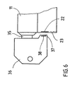
- the key 35 is provided with a key handle 36 having a portion 37 in which the transponder or antenna 38 is integrated.
- the portion is formed as protruding toward the lock cylinder. Accordingly, this section has a particularly small distance from the end face of the key in the inserted state of the key Cylinder housing on. This causes a short signal transmission path.
- the clutch has a Kupplungsmit legislative 26 with at least one projection 27 ', 27' ', 27' '' on. 2, the Kupplungsmit disturbing 26 is freely rotatable within the coupling body 18, since the projections 27 ', 27' ', 27' '' above a shoulder 28 of the coupling body 18 with corresponding recesses 29 for the projections 27 ', 27' ', 27' '' runs.
- the Kupplungsmit protagonist can stand in constant operative connection with the rotatable connection piece 30 of the lock core and is held by a spring 39 in the illustrated axial resting state.
- a microswitch 33 When inserting the mechanically matching key, a microswitch 33 is actuated by means of an axial extension 32, through which the electronic controller 20 is turned on.
- the electronic control generated after appropriate evaluation and authorization the electrical switching signal through which attracts the clutch.
- the authorization can be checked by evaluating a suitable transponder signal, which is conducted by the inserted key via the antenna 22 and the slip ring contacts 25 to the evaluation unit within the electronic control.
- the coupling cam 26 When tightening, for example, an electromagnet of the coupling 16, the coupling cam 26 is moved further in the direction of the arrow 31, so that the projections 27 ', 27' ', 27 "' come into engagement with the recesses 29.
- a non-rotatable connection of the locking core with the coupling body By turning the key, the lock core now turns the coupling body, which in turn is non-rotatably connected to the locking lug 17. The lock can be unlocked.
- the drop of the clutch can basically be done at any time of the closing process and thus at any angular position of the locking lug. It is also possible that the closing nose assumes any angular position by the knob. However, it is desirable that the key and the locking lug are always in a defined angular position to each other.
- the projections 27 ', 27 ", 27"' of Kupplungs mit choirs distributed asymmetrically along the circumference, so that in only one angular position (Fig. 5 a, b), the projections 27 ', 27'',27''' in the recesses 29 can engage.
- the projections may be axially or, as shown, radially aligned. In principle, a single lead can be sufficient.
- a Kupplungsmit counseling with three projections 27 ', 27'',27''' is provided in the embodiment shown, which is formed substantially Y-shaped.
- the web 27 ''' is in this case formed wider than the two legs 27', 27 ''.
- the electromechanical lock is completely independent of external devices. It is of course possible to connect via the slip ring contacts 25, for example, an external power supply. It is also possible to connect via this the electronic control to a central data processing system. Finally, it is also possible, the clutch via such slip ring contacts with the required switching signal to supply. In this case, the entire electronic control could be located externally.
Landscapes
- Physics & Mathematics (AREA)
- Electromagnetism (AREA)
- Lock And Its Accessories (AREA)
Claims (10)
- Serrure cylindrique électromécanique, destinée notamment à des systèmes de fermeture, comportant une carcasse cylindrique (11) pourvue de deux logements (12, 13) en regard l'un de l'autre, dont le premier logement (12) supporte en rotation un noyau de fermeture (14) actionnable au moyen d'une clef afin de faire tourner un panneton (17) qui actionne le pêne dormant, et dont le second logement (13) contient un dispositif de couplage (16) à actionnement électrique qui commute sous l'effet d'un signal électrique de commutation et entraîne une liaison solidaire en rotation entre le panneton (17) et le noyau de fermeture (14) pour permettre à la clef de faire tourner le panneton (17),
caractérisée en ce que
le dispositif de couplage (16) comprend un organe de couplage (18) solidaire en rotation avec le panneton, et un entraîneur (26) pourvu de saillies asymétriques en périphérie et qui s'engagent dans des évidements correspondants à l'organe de couplage (18), dans une seule position angulaire par rapport à la clef, lorsque le dispositif de couplage est dans une position de travail. - Serrure cylindrique selon la revendication 1,
caractérisée en ce que
le dispositif de couplage permet, au repos, une rotation libre du noyau de fermeture (14) lorsque la clef est mécaniquement adaptée. - Serrure cylindrique selon l'une des revendications 1 ou 2,
caractérisée en ce que
le signal électrique de commutation est provoqué par une de commande électronique (20) comprenant une antenne (22) coopérant avec un transpondeur passif de la clef. - Serrure cylindrique selon l'une des revendications 1 à 3,
caractérisée en ce que
l'antenne (22) pour le transpondeur ou pour l'unité réceptrice est intégrée dans la zone avant (34) de la serrure cylindrique et est liée à la commande électronique. - Serrure cylindrique selon l'une des revendications 1 à 4,
caractérisée en ce qu'
un bouton rotatif (19) à actionnement manuel est supporté en rotation du côté du cylindre de fermeture qui est en regard du premier logement (12), le bouton rotatif coopérant avec le panneton (17) et contenant au moins partiellement la commande électronique (20). - Serrure cylindrique selon la revendication 5,
caractérisée en ce que
l'alimentation énergétique est assurée par une pile logeant dans le bouton rotatif. - Serrure cylindrique selon la revendication 5 ou 6,
caractérisée en ce que
le bouton rotatif (19) est solidaire en rotation de l'organe de couplage(18). - Serrure cylindrique selon l'une des revendications 1 à 7,
caractérisée en ce que
dans la carcasse cylindrique, au moins un moyen de commutation (33) est actionnable au moyen de la clef mécaniquement adaptée pour mettre en marche la commande électronique. - Serrure cylindrique selon la revendication 8,
caractérisée en ce que
le moyen de commutation permet de mettre en marche la commande électronique pendant un temps prédéterminé. - Serrure cylindrique selon l'une des revendications 1 à 9,
caractérisée en ce que
la carcasse cylindrique présente des dimensions normalisées ou standardisées.
Applications Claiming Priority (2)
| Application Number | Priority Date | Filing Date | Title |
|---|---|---|---|
| DE19930054A DE19930054C5 (de) | 1999-06-30 | 1999-06-30 | Elektromechanisches Schließsystem |
| DE19930054 | 1999-06-30 |
Publications (2)
| Publication Number | Publication Date |
|---|---|
| EP1065335A1 EP1065335A1 (fr) | 2001-01-03 |
| EP1065335B1 true EP1065335B1 (fr) | 2007-03-21 |
Family
ID=7913111
Family Applications (1)
| Application Number | Title | Priority Date | Filing Date |
|---|---|---|---|
| EP00113546A Expired - Lifetime EP1065335B1 (fr) | 1999-06-30 | 2000-06-27 | Système de verrouillage électromécanique |
Country Status (3)
| Country | Link |
|---|---|
| EP (1) | EP1065335B1 (fr) |
| AT (1) | ATE357571T1 (fr) |
| DE (2) | DE19930054C5 (fr) |
Families Citing this family (21)
| Publication number | Priority date | Publication date | Assignee | Title |
|---|---|---|---|---|
| ATE375425T1 (de) | 2000-07-21 | 2007-10-15 | Hid Gmbh | Schliesszylinder mit einer anordnung zum kontaktlosen übertragen eines signals |
| DE10164831B4 (de) * | 2001-02-16 | 2005-11-03 | Buga Technologies Gmbh | Programmierbarer elektromechanischer Schließzylinder |
| DE20117800U1 (de) * | 2001-10-31 | 2003-03-20 | DOM Sicherheitstechnik GmbH & Co KG, 50321 Brühl | Elektronischer Schrank- oder Automatverschluss |
| DE10209037B4 (de) * | 2002-03-02 | 2007-10-11 | Hid Gmbh | Verfahren und Vorrichtung zum Überwachen der Spannung einer Batterie |
| DE10217216B4 (de) * | 2002-03-02 | 2005-06-23 | Buga Technologies Gmbh | Betätigungsanordnung für einen Schalter |
| DE10225368C1 (de) * | 2002-06-06 | 2003-07-31 | Buga Schliessysteme Ag | Schließzylinder mit kontaktloser Übertragung eines Signals |
| US6865916B2 (en) * | 2002-08-28 | 2005-03-15 | Ilan Goldman | Door cylinder lock |
| FR2849085A1 (fr) * | 2003-04-16 | 2004-06-25 | Reelax France Sa | Cylindre de serrure perfectionne et serrure correspondante |
| DE10328297A1 (de) * | 2003-06-23 | 2005-01-20 | Buga Technologies Gmbh | Elektromechanischer Schließzylinder |
| PL1574643T3 (pl) | 2004-03-11 | 2012-06-29 | Keso Ag | Elektromechaniczny cylinder zamykający |
| EP1739631B1 (fr) | 2005-06-24 | 2012-10-24 | Assa Abloy Ab | Serrure cylindrique modulaire |
| WO2007000576A1 (fr) * | 2005-06-28 | 2007-01-04 | Cintor Limited | Verrou a commande electronique |
| US7845202B2 (en) | 2006-09-22 | 2010-12-07 | Assa Abloy Ab | Interchangeable electromechanical lock core |
| ES2331864B1 (es) * | 2008-07-15 | 2010-10-28 | Salto Systems, S.L. | Cilindro electromecanico para cerradura. |
| AR109978A1 (es) | 2016-10-19 | 2019-02-13 | Best Access Solutions Inc | Núcleo de cerradura electromecánica |
| EP3679207B1 (fr) | 2017-09-08 | 2022-08-03 | Dormakaba USA Inc. | Partie centrale de verrou électromécanique |
| US11466473B2 (en) | 2018-04-13 | 2022-10-11 | Dormakaba Usa Inc | Electro-mechanical lock core |
| AU2019252796B2 (en) | 2018-04-13 | 2022-04-28 | Dormakaba Usa Inc. | Electro-mechanical lock core |
| USD891901S1 (en) | 2019-04-05 | 2020-08-04 | Dormakaba Usa Inc. | Knob |
| US11655653B1 (en) | 2022-04-15 | 2023-05-23 | Digilock Asia Ltd. | Electronically operated lock cylinder |
| US12152409B2 (en) | 2022-04-15 | 2024-11-26 | Security People, Inc. | Electronic mortise lock cylinder |
Family Cites Families (11)
| Publication number | Priority date | Publication date | Assignee | Title |
|---|---|---|---|---|
| CH669425A5 (fr) * | 1985-06-12 | 1989-03-15 | Bauer Kaba Ag | |
| US4856310A (en) * | 1987-04-29 | 1989-08-15 | Raoul Parienti | Electronic lock |
| DE3742189A1 (de) * | 1987-12-12 | 1989-06-29 | Zeiss Ikon Ag | Schliesszylinder |
| DE3800414A1 (de) * | 1988-01-09 | 1989-07-20 | Bks Gmbh | Schliesszylinder, insbesondere fuer einsteckschloesser bestimmter profilzylinder |
| FR2655367B1 (fr) * | 1989-12-05 | 1992-04-03 | Vachette Sa | Serrure a barillet double a condamnation mecanique et electrique. |
| DE4019624C2 (de) * | 1990-06-20 | 2000-05-25 | Fliether Karl Gmbh & Co | Doppelschließzylinder mit einer elektrischen Verriegelungseinrichtung |
| IT1258149B (it) * | 1992-09-15 | 1996-02-20 | Italiana Serrature Affini | Serratura ad abilitazione elettrica |
| DE4240560A1 (de) * | 1992-12-02 | 1994-06-09 | Winkhaus Fa August | Zutrittskontrollanlage |
| DE19603320C2 (de) * | 1996-01-31 | 1999-01-14 | Guenter Uhlmann | Elektronisch programmierbares Schließsystem mit Schloß und Schlüssel |
| IT1297493B1 (it) * | 1997-10-03 | 1999-12-17 | Silca Spa | Unita' di cilindro e chiave a funzionamento meccatronico per serratura |
| DE19848286B4 (de) * | 1998-10-20 | 2009-10-08 | Uhlmann, Günter | Kopplungsbaugruppe für ein Elektromechanisches Schließsystem |
-
1999
- 1999-06-30 DE DE19930054A patent/DE19930054C5/de not_active Expired - Fee Related
-
2000
- 2000-06-27 EP EP00113546A patent/EP1065335B1/fr not_active Expired - Lifetime
- 2000-06-27 AT AT00113546T patent/ATE357571T1/de not_active IP Right Cessation
- 2000-06-27 DE DE50014176T patent/DE50014176D1/de not_active Expired - Fee Related
Also Published As
| Publication number | Publication date |
|---|---|
| ATE357571T1 (de) | 2007-04-15 |
| EP1065335A1 (fr) | 2001-01-03 |
| DE50014176D1 (de) | 2007-05-03 |
| DE19930054C5 (de) | 2006-11-23 |
| DE19930054C2 (de) | 2002-09-19 |
| DE19930054A1 (de) | 2001-01-18 |
Similar Documents
| Publication | Publication Date | Title |
|---|---|---|
| DE19930054C5 (de) | Elektromechanisches Schließsystem | |
| DE19861400B4 (de) | Schließzylinder | |
| DE3853828T2 (de) | Verriegelungsvorrichtung. | |
| DE69320683T2 (de) | Elektromechanische Schlossanordnung | |
| DE19983294B4 (de) | Elektrisch gesteuertes Schloss | |
| EP0401647B1 (fr) | Système de verrouillage | |
| EP1636454A1 (fr) | Barillet electromagnetique | |
| EP1576246A1 (fr) | Dispositif de verrouillage | |
| EP0324096B1 (fr) | Serrure à cylindre, notamment cylindre pour serrure encastrée | |
| WO1982004459A1 (fr) | Barillet de serrure a verrouillage electromagnetique integre | |
| EP0110835A2 (fr) | Cylindre de serrure à verrouillage électromagnétique intégré | |
| DE69002786T2 (de) | Schloss mit einem elektronischen Schlüssel. | |
| EP0224607A1 (fr) | Dispositif de fermeture comportant un système électronique d'identification | |
| DE19604442A1 (de) | Sicherheitsvorrichtung für elektronische Schlösser | |
| DE19957046A1 (de) | Schließsystem, insbesondere für Kraftfahrzeuge | |
| EP0280755B1 (fr) | Serrure électrique à commande électronique; application aux serrures à mortaise | |
| EP0094592A1 (fr) | Dispositif de fermeture | |
| DE10225649B4 (de) | Ferngesteuert freigebbarer Schließzylinder | |
| EP1736622B1 (fr) | Barillet | |
| DE19602438C2 (de) | Kombinationsschloß | |
| DE19615775C2 (de) | Schließzylinder | |
| DE29911356U1 (de) | Antennenanordnung für ein durch Funksignal betätigbares Schließsystem | |
| DE29911355U1 (de) | Elektromechanisches Schloß | |
| DE10225368C1 (de) | Schließzylinder mit kontaktloser Übertragung eines Signals | |
| DE29911353U1 (de) | Elektromechanisches Schließsystem |
Legal Events
| Date | Code | Title | Description |
|---|---|---|---|
| PUAI | Public reference made under article 153(3) epc to a published international application that has entered the european phase |
Free format text: ORIGINAL CODE: 0009012 |
|
| AK | Designated contracting states |
Kind code of ref document: A1 Designated state(s): AT BE CH CY DE DK ES FI FR GB GR IE IT LI LU MC NL PT SE |
|
| AX | Request for extension of the european patent |
Free format text: AL;LT;LV;MK;RO;SI |
|
| 17P | Request for examination filed |
Effective date: 20010630 |
|
| AKX | Designation fees paid |
Free format text: AT BE CH CY DE DK ES FI FR GB GR IE IT LI LU MC NL PT SE |
|
| 17Q | First examination report despatched |
Effective date: 20020402 |
|
| RAP1 | Party data changed (applicant data changed or rights of an application transferred) |
Owner name: BUGA TECHNOLOGIES GMBH |
|
| RAP1 | Party data changed (applicant data changed or rights of an application transferred) |
Owner name: BUGA TECHNOLOGIES GMBH |
|
| GRAP | Despatch of communication of intention to grant a patent |
Free format text: ORIGINAL CODE: EPIDOSNIGR1 |
|
| GRAS | Grant fee paid |
Free format text: ORIGINAL CODE: EPIDOSNIGR3 |
|
| GRAA | (expected) grant |
Free format text: ORIGINAL CODE: 0009210 |
|
| AK | Designated contracting states |
Kind code of ref document: B1 Designated state(s): AT BE CH CY DE DK ES FI FR GB GR IE IT LI LU MC NL PT SE |
|
| PG25 | Lapsed in a contracting state [announced via postgrant information from national office to epo] |
Ref country code: FI Free format text: LAPSE BECAUSE OF FAILURE TO SUBMIT A TRANSLATION OF THE DESCRIPTION OR TO PAY THE FEE WITHIN THE PRESCRIBED TIME-LIMIT Effective date: 20070321 |
|
| REG | Reference to a national code |
Ref country code: GB Ref legal event code: FG4D Free format text: NOT ENGLISH |
|
| REG | Reference to a national code |
Ref country code: CH Ref legal event code: EP |
|
| REF | Corresponds to: |
Ref document number: 50014176 Country of ref document: DE Date of ref document: 20070503 Kind code of ref document: P |
|
| GBT | Gb: translation of ep patent filed (gb section 77(6)(a)/1977) |
Effective date: 20070423 |
|
| RAP2 | Party data changed (patent owner data changed or rights of a patent transferred) |
Owner name: HID GMBH |
|
| REG | Reference to a national code |
Ref country code: IE Ref legal event code: FG4D Free format text: LANGUAGE OF EP DOCUMENT: GERMAN |
|
| PG25 | Lapsed in a contracting state [announced via postgrant information from national office to epo] |
Ref country code: SE Free format text: LAPSE BECAUSE OF FAILURE TO SUBMIT A TRANSLATION OF THE DESCRIPTION OR TO PAY THE FEE WITHIN THE PRESCRIBED TIME-LIMIT Effective date: 20070621 |
|
| NLT2 | Nl: modifications (of names), taken from the european patent patent bulletin |
Owner name: HID GMBH Effective date: 20070516 |
|
| PG25 | Lapsed in a contracting state [announced via postgrant information from national office to epo] |
Ref country code: ES Free format text: LAPSE BECAUSE OF FAILURE TO SUBMIT A TRANSLATION OF THE DESCRIPTION OR TO PAY THE FEE WITHIN THE PRESCRIBED TIME-LIMIT Effective date: 20070702 |
|
| NLT1 | Nl: modifications of names registered in virtue of documents presented to the patent office pursuant to art. 16 a, paragraph 1 |
Owner name: HID GMBH |
|
| PG25 | Lapsed in a contracting state [announced via postgrant information from national office to epo] |
Ref country code: PT Free format text: LAPSE BECAUSE OF FAILURE TO SUBMIT A TRANSLATION OF THE DESCRIPTION OR TO PAY THE FEE WITHIN THE PRESCRIBED TIME-LIMIT Effective date: 20070821 |
|
| ET | Fr: translation filed | ||
| REG | Reference to a national code |
Ref country code: FR Ref legal event code: CD |
|
| REG | Reference to a national code |
Ref country code: IE Ref legal event code: FD4D |
|
| BERE | Be: lapsed |
Owner name: BUGA TECHNOLOGIES G.M.B.H. Effective date: 20070630 |
|
| PLBE | No opposition filed within time limit |
Free format text: ORIGINAL CODE: 0009261 |
|
| STAA | Information on the status of an ep patent application or granted ep patent |
Free format text: STATUS: NO OPPOSITION FILED WITHIN TIME LIMIT |
|
| PG25 | Lapsed in a contracting state [announced via postgrant information from national office to epo] |
Ref country code: DK Free format text: LAPSE BECAUSE OF FAILURE TO SUBMIT A TRANSLATION OF THE DESCRIPTION OR TO PAY THE FEE WITHIN THE PRESCRIBED TIME-LIMIT Effective date: 20070321 Ref country code: IE Free format text: LAPSE BECAUSE OF FAILURE TO SUBMIT A TRANSLATION OF THE DESCRIPTION OR TO PAY THE FEE WITHIN THE PRESCRIBED TIME-LIMIT Effective date: 20070321 Ref country code: MC Free format text: LAPSE BECAUSE OF NON-PAYMENT OF DUE FEES Effective date: 20070630 |
|
| REG | Reference to a national code |
Ref country code: CH Ref legal event code: PL |
|
| 26N | No opposition filed |
Effective date: 20071227 |
|
| PG25 | Lapsed in a contracting state [announced via postgrant information from national office to epo] |
Ref country code: BE Free format text: LAPSE BECAUSE OF NON-PAYMENT OF DUE FEES Effective date: 20070630 |
|
| PG25 | Lapsed in a contracting state [announced via postgrant information from national office to epo] |
Ref country code: LI Free format text: LAPSE BECAUSE OF NON-PAYMENT OF DUE FEES Effective date: 20070630 Ref country code: GR Free format text: LAPSE BECAUSE OF FAILURE TO SUBMIT A TRANSLATION OF THE DESCRIPTION OR TO PAY THE FEE WITHIN THE PRESCRIBED TIME-LIMIT Effective date: 20070622 Ref country code: CH Free format text: LAPSE BECAUSE OF NON-PAYMENT OF DUE FEES Effective date: 20070630 |
|
| PG25 | Lapsed in a contracting state [announced via postgrant information from national office to epo] |
Ref country code: AT Free format text: LAPSE BECAUSE OF NON-PAYMENT OF DUE FEES Effective date: 20070627 |
|
| PGFP | Annual fee paid to national office [announced via postgrant information from national office to epo] |
Ref country code: IT Payment date: 20080625 Year of fee payment: 9 |
|
| PGFP | Annual fee paid to national office [announced via postgrant information from national office to epo] |
Ref country code: DE Payment date: 20080821 Year of fee payment: 9 Ref country code: NL Payment date: 20080626 Year of fee payment: 9 |
|
| PGFP | Annual fee paid to national office [announced via postgrant information from national office to epo] |
Ref country code: GB Payment date: 20080509 Year of fee payment: 9 |
|
| PGFP | Annual fee paid to national office [announced via postgrant information from national office to epo] |
Ref country code: FR Payment date: 20081113 Year of fee payment: 9 |
|
| PG25 | Lapsed in a contracting state [announced via postgrant information from national office to epo] |
Ref country code: CY Free format text: LAPSE BECAUSE OF FAILURE TO SUBMIT A TRANSLATION OF THE DESCRIPTION OR TO PAY THE FEE WITHIN THE PRESCRIBED TIME-LIMIT Effective date: 20070321 |
|
| PG25 | Lapsed in a contracting state [announced via postgrant information from national office to epo] |
Ref country code: LU Free format text: LAPSE BECAUSE OF NON-PAYMENT OF DUE FEES Effective date: 20070627 |
|
| REG | Reference to a national code |
Ref country code: GB Ref legal event code: 732E Free format text: REGISTERED BETWEEN 20090917 AND 20090923 |
|
| GBPC | Gb: european patent ceased through non-payment of renewal fee |
Effective date: 20090627 |
|
| NLV4 | Nl: lapsed or anulled due to non-payment of the annual fee |
Effective date: 20100101 |
|
| REG | Reference to a national code |
Ref country code: FR Ref legal event code: ST Effective date: 20100226 |
|
| PG25 | Lapsed in a contracting state [announced via postgrant information from national office to epo] |
Ref country code: FR Free format text: LAPSE BECAUSE OF NON-PAYMENT OF DUE FEES Effective date: 20090630 |
|
| PG25 | Lapsed in a contracting state [announced via postgrant information from national office to epo] |
Ref country code: GB Free format text: LAPSE BECAUSE OF NON-PAYMENT OF DUE FEES Effective date: 20090627 |
|
| PG25 | Lapsed in a contracting state [announced via postgrant information from national office to epo] |
Ref country code: DE Free format text: LAPSE BECAUSE OF NON-PAYMENT OF DUE FEES Effective date: 20100101 |
|
| PG25 | Lapsed in a contracting state [announced via postgrant information from national office to epo] |
Ref country code: NL Free format text: LAPSE BECAUSE OF NON-PAYMENT OF DUE FEES Effective date: 20100101 |
|
| PG25 | Lapsed in a contracting state [announced via postgrant information from national office to epo] |
Ref country code: IT Free format text: LAPSE BECAUSE OF NON-PAYMENT OF DUE FEES Effective date: 20090627 |