EP1065384A1 - Dispositif de pompage pour plusieurs carburants - Google Patents
Dispositif de pompage pour plusieurs carburants Download PDFInfo
- Publication number
- EP1065384A1 EP1065384A1 EP99202093A EP99202093A EP1065384A1 EP 1065384 A1 EP1065384 A1 EP 1065384A1 EP 99202093 A EP99202093 A EP 99202093A EP 99202093 A EP99202093 A EP 99202093A EP 1065384 A1 EP1065384 A1 EP 1065384A1
- Authority
- EP
- European Patent Office
- Prior art keywords
- pump
- pumping device
- discharge
- valve
- shut
- Prior art date
- Legal status (The legal status is an assumption and is not a legal conclusion. Google has not performed a legal analysis and makes no representation as to the accuracy of the status listed.)
- Withdrawn
Links
- 238000005086 pumping Methods 0.000 title claims abstract description 31
- 239000000446 fuel Substances 0.000 title claims abstract description 27
- 239000007788 liquid Substances 0.000 description 8
- 238000007872 degassing Methods 0.000 description 4
- 238000011084 recovery Methods 0.000 description 4
- 238000007789 sealing Methods 0.000 description 4
- 230000002349 favourable effect Effects 0.000 description 3
- 239000012530 fluid Substances 0.000 description 3
- 230000007257 malfunction Effects 0.000 description 2
- 238000007599 discharging Methods 0.000 description 1
- 238000012423 maintenance Methods 0.000 description 1
- 238000004519 manufacturing process Methods 0.000 description 1
Images


Classifications
-
- B—PERFORMING OPERATIONS; TRANSPORTING
- B67—OPENING, CLOSING OR CLEANING BOTTLES, JARS OR SIMILAR CONTAINERS; LIQUID HANDLING
- B67D—DISPENSING, DELIVERING OR TRANSFERRING LIQUIDS, NOT OTHERWISE PROVIDED FOR
- B67D7/00—Apparatus or devices for transferring liquids from bulk storage containers or reservoirs into vehicles or into portable containers, e.g. for retail sale purposes
- B67D7/04—Apparatus or devices for transferring liquids from bulk storage containers or reservoirs into vehicles or into portable containers, e.g. for retail sale purposes for transferring fuels, lubricants or mixed fuels and lubricants
-
- B—PERFORMING OPERATIONS; TRANSPORTING
- B67—OPENING, CLOSING OR CLEANING BOTTLES, JARS OR SIMILAR CONTAINERS; LIQUID HANDLING
- B67D—DISPENSING, DELIVERING OR TRANSFERRING LIQUIDS, NOT OTHERWISE PROVIDED FOR
- B67D7/00—Apparatus or devices for transferring liquids from bulk storage containers or reservoirs into vehicles or into portable containers, e.g. for retail sale purposes
- B67D7/06—Details or accessories
- B67D7/76—Arrangements of devices for purifying liquids to be transferred, e.g. of filters, of air or water separators
- B67D7/763—Arrangements of devices for purifying liquids to be transferred, e.g. of filters, of air or water separators of air separators
-
- F—MECHANICAL ENGINEERING; LIGHTING; HEATING; WEAPONS; BLASTING
- F04—POSITIVE - DISPLACEMENT MACHINES FOR LIQUIDS; PUMPS FOR LIQUIDS OR ELASTIC FLUIDS
- F04D—NON-POSITIVE-DISPLACEMENT PUMPS
- F04D13/00—Pumping installations or systems
- F04D13/02—Units comprising pumps and their driving means
-
- F—MECHANICAL ENGINEERING; LIGHTING; HEATING; WEAPONS; BLASTING
- F04—POSITIVE - DISPLACEMENT MACHINES FOR LIQUIDS; PUMPS FOR LIQUIDS OR ELASTIC FLUIDS
- F04D—NON-POSITIVE-DISPLACEMENT PUMPS
- F04D9/00—Priming; Preventing vapour lock
- F04D9/04—Priming; Preventing vapour lock using priming pumps; using booster pumps to prevent vapour-lock
- F04D9/041—Priming; Preventing vapour lock using priming pumps; using booster pumps to prevent vapour-lock the priming pump having evacuating action
Definitions
- the invention relates to a pumping device for several different, relatively volatile vehicle fuels.
- a pumping device is generally known as multiproduct dispenser (MPD) and contains generally 2, 3 or 4 pumping units, one per product. Examples of these products are leadfree petrol, normal petrol, super petrol and diesel. Generally each of the pump units feeds two dispensing nozzles.
- MPD multiproduct dispenser
- the object of the invention is to improve a pumping device of this kind by applying teachings known from Dutch patent application 9 401 455.
- This last mentioned publication shows a pumping device for relatively volatile vehicle of fuel for a single product dispenser.
- the pumping capacity of the gas pump can be limited to that maximum use.
- the gas pump will be of the same capacity as a single product dispenser with two dispensing nozzles.
- a further favourable development of the pumping device according to the invention is characterized in claim 2.
- the manufacturing costs of the pumping device are very limited.
- the power of the electric motor used according to this preferred embodiment is only slightly higher than the electric motor that would be necessary for driving one fuel pump.
- a favourable embodiment of the pumping device according to the invention is characterized in claim 3.
- the characterizing feature of claim 4 is preferably applied. In case of malfunction of one the fuel pumps it can easily be replaced by a corresponding pump without fully disassembling the pumping device.
- the discharge valve is closed, so as to prevent that gas is discharged with the fuel.
- a further improvement is characterized in claim 7.
- the pump cartridge 1 becomes a simple centrifugal pump with, for instance, a diameter of 100 mm if it is a three stage pump. A two stage pump would need a diameter 130 mm.
- the pump cartridges 1 can easily be exchanged if necessary.
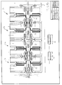
- the total size of the four pumps can be reduced to a space of only 480 x 310 x 280 mm so that the dispenser becomes considerably smaller than the prior art.
- the four centrifugal pumps are driven with one motor 2, on one side of which a vacuum pump 3 is mounted and on the other shaft side 4 the pulley (not shown) to drive the four centrifugal fuel pumps is mounted.
- the vacuum pump 3 will be chosen such that it has a sufficient capacity to provide for degassing and for vapour recovery.
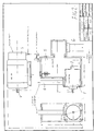
- the pump housing 5 has an intake 6 which is connected to a supply of a specific fuel.
- the fuel pump 1 has a fuel inlet 7 that draws in fuel from the interior of the pump housing 5.
- a pressure outlet of the pump 1 is connected to a discharge 8 which leads to a dispenser nozzle via a flow meter.
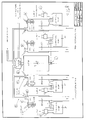
- Fig. 4 shows the arrangement of the driving gear for the pumping device.
- the motor 2 drives a double pulley 10 which drivingly engages pulleys 11 and 12 by means of the V-belts.
- Each of the pulleys 11 and 12 is connected with a gear that is in meshing engagement with gears 13 on the shafts of the pump cartridges.
- centrifugal pump 15 is separated from the degasser or pump housing which allows a very economic degasser design.
- a non return valve 17 prevents the liquid to flow back to the underground reservoir, as soon as the pump is switched off. This non return valve is not really necessary.
- Two electric valves 25 and 26 in figure 8 close when the motor stops running, making any flow back of the liquid impossible and keeping at the same time the pump under underpressure.
- the vertical shaft position of motor 18 and centrifugal pumps 15 and the relative positioning of the components as shown in fig. 5, result in a two stage centrifugal pump having its shaft sealings exposed to the suction side in a favourable manner. This has the advantage that the pressure drop over the shaft sealings is never higher than about 0,5 bar and enables the use of simple lip seals.
- the pressure side of the pump has no shaft sealings.
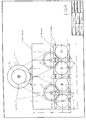
- the central motor 18 as shown in fig. 8 drives the, in this case four centrigufal pumps 15 by a set of gear wheels indicated in fig. 6 with one side of its shaft 21 while with the other shaft extremity 22 a vacuum pump is driven. It will be clear that instead of 4 pumping units also 3 or 2 pumping units can be used.
- the motor 18 starts to run driving the vacuum pump and the 4 centrifugal pumps 15.
- the centrifugal pumps 15 do not have to deliver immediately liquid because it takes a few seconds before the nozzle is taken to the tank of the vehicle and opened.
- the vacuum pomp however creates immediately an underpressure in the suction pipes 23 with which it is connected to the four pump housings.
- the float switches by means of their upper read relay keep the four electric vacuum shut off valves 25 closed and the vacuum pump evacuates only the gas in the suction pipes 23.
- the upper read relay of the corresponding float switch 24 deactivates the electric vacuum shut off valve 25 which opens and enable the vacuum pump to restore the level of the liquid at its maximum value by evacuating the gas on top of the liquid in the corresponding pump housing.
- the lower read relay of the corresponding float switch 24 closes the corresponding electric discharge shut off valve 6 in the discharge pipe of the centrifugal pump, the flow rate of which drops to zero, while the vacuum pump evacuates the gas in the pump housing and tries to restore the maximum liquid level.
- control means would then close the electric shut off valves in the output of the centrifugal pump 26 and the vacuum shut off valve 25 on top of the pump housing, isolating in that way the problematic pumping unit from the others which, however, continue to function. At the same time an error signal can be generated warning an operator of the faulty situation.
- the capacity of the vacuum pump is of course adapted for both degassing and vapour recovery.
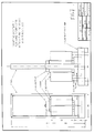
- the pumps are separated from the pump housings, in the same way as the embodiment of figures 1-4.
- the pump housings of this embodiment therefore can have the same embodiment as that of the pumping device of these figures 1-4.
- the hydrodynamic liquid pump 30 is here designed as a single stage centrifugal pump. It is designed with a through-going shaft, such that two, three or more pumps can be assembled as shown in figure 10.
- the advantage described for the embodiment of fig. 1-4 concerning the low pressure drop on the shaft sealings is also valid here.
- the two different lengths of grooved shafts 31, 32 shown in figure 10 connect the respective shafts 33 of the pumps 30 in such a way that the units can be assembled one against the other.
Landscapes
- Engineering & Computer Science (AREA)
- Mechanical Engineering (AREA)
- General Engineering & Computer Science (AREA)
- Structures Of Non-Positive Displacement Pumps (AREA)
Priority Applications (3)
| Application Number | Priority Date | Filing Date | Title |
|---|---|---|---|
| EP99202093A EP1065384A1 (fr) | 1999-06-28 | 1999-06-28 | Dispositif de pompage pour plusieurs carburants |
| PCT/EP2000/006045 WO2001000994A1 (fr) | 1999-06-28 | 2000-06-28 | Dispositif de pompage pour plusieurs carburants |
| AU59800/00A AU5980000A (en) | 1999-06-28 | 2000-06-28 | Pumping device for several fuels |
Applications Claiming Priority (1)
| Application Number | Priority Date | Filing Date | Title |
|---|---|---|---|
| EP99202093A EP1065384A1 (fr) | 1999-06-28 | 1999-06-28 | Dispositif de pompage pour plusieurs carburants |
Publications (1)
| Publication Number | Publication Date |
|---|---|
| EP1065384A1 true EP1065384A1 (fr) | 2001-01-03 |
Family
ID=8240375
Family Applications (1)
| Application Number | Title | Priority Date | Filing Date |
|---|---|---|---|
| EP99202093A Withdrawn EP1065384A1 (fr) | 1999-06-28 | 1999-06-28 | Dispositif de pompage pour plusieurs carburants |
Country Status (3)
| Country | Link |
|---|---|
| EP (1) | EP1065384A1 (fr) |
| AU (1) | AU5980000A (fr) |
| WO (1) | WO2001000994A1 (fr) |
Citations (5)
| Publication number | Priority date | Publication date | Assignee | Title |
|---|---|---|---|---|
| US1549608A (en) * | 1923-02-19 | 1925-08-11 | Clarence R Raynes | Pressure pump |
| GB350551A (en) * | 1930-03-14 | 1931-06-15 | Drysdale & Co Ltd | Improvements in and relating to combined water and air pump units |
| FR875245A (fr) * | 1941-05-13 | 1942-09-11 | Rateau Soc | Amorçage automatique d'une pompe centrifuge |
| US5323817A (en) * | 1991-04-30 | 1994-06-28 | Dresser Industries, Inc. | Gasoline dispenser with vapor recovery system |
| DE29512158U1 (de) * | 1994-08-08 | 1995-10-19 | Moretti, Bruno, Vigevano | Vorrichtung zum Betreiben von Pumpen in einer Anlage zum Schäumen von Polyurethan |
Family Cites Families (1)
| Publication number | Priority date | Publication date | Assignee | Title |
|---|---|---|---|---|
| NL9401455A (nl) * | 1994-09-07 | 1996-04-01 | Andre S J Van Coillie En Johan | Zelfaanzuigende centrifugaalpomp-vakuumpomp-kombinatie voor o.a. vloeibare brandstoffen zoals benzine, gasoil, kerozene enz. met verbeterde ontgasser en geintegreerde övapor recoveryö mogelijkheid. |
-
1999
- 1999-06-28 EP EP99202093A patent/EP1065384A1/fr not_active Withdrawn
-
2000
- 2000-06-28 AU AU59800/00A patent/AU5980000A/en not_active Abandoned
- 2000-06-28 WO PCT/EP2000/006045 patent/WO2001000994A1/fr not_active Ceased
Patent Citations (5)
| Publication number | Priority date | Publication date | Assignee | Title |
|---|---|---|---|---|
| US1549608A (en) * | 1923-02-19 | 1925-08-11 | Clarence R Raynes | Pressure pump |
| GB350551A (en) * | 1930-03-14 | 1931-06-15 | Drysdale & Co Ltd | Improvements in and relating to combined water and air pump units |
| FR875245A (fr) * | 1941-05-13 | 1942-09-11 | Rateau Soc | Amorçage automatique d'une pompe centrifuge |
| US5323817A (en) * | 1991-04-30 | 1994-06-28 | Dresser Industries, Inc. | Gasoline dispenser with vapor recovery system |
| DE29512158U1 (de) * | 1994-08-08 | 1995-10-19 | Moretti, Bruno, Vigevano | Vorrichtung zum Betreiben von Pumpen in einer Anlage zum Schäumen von Polyurethan |
Also Published As
| Publication number | Publication date |
|---|---|
| AU5980000A (en) | 2001-01-31 |
| WO2001000994A1 (fr) | 2001-01-04 |
Similar Documents
| Publication | Publication Date | Title |
|---|---|---|
| US6152689A (en) | Self-priming type cetrifugal pump | |
| US4067663A (en) | Sewage pump priming system | |
| US20250035112A1 (en) | Grease pump unit comprising two serially connected pumps | |
| EP0701062B1 (fr) | Dispositif de pompage | |
| RU95114955A (ru) | Нагнетающее устройство для относительно летучей жидкости | |
| EP1065384A1 (fr) | Dispositif de pompage pour plusieurs carburants | |
| US8316811B1 (en) | Method and apparatus for priming various components of a diesel engine | |
| EP3395754B1 (fr) | Unité de pompe à carburant pour une unité de distribution de carburant et procédé de gestion d'une unité de pompe à carburant pour une unité de distribution de carburant | |
| US4913629A (en) | Wellpoint pumping system | |
| CN207333176U (zh) | 一种具有压力补偿的内啮合齿轮泵 | |
| GB2073371A (en) | Valves | |
| WO2007111624A1 (fr) | Procédé et appareil pour distribuer de l'huile de cuisson fraîche | |
| US2307060A (en) | Liquid dispensing apparatus | |
| EP0976441A1 (fr) | Dispositif pour l'aération de l'eau, des boissons et des liquides en générales | |
| SE2050908A1 (en) | Filter device for a fuel dispensing system | |
| CN208950995U (zh) | 一种千型压裂车多功能液压系统 | |
| US5222532A (en) | Device for dispensing hydrocarbons with vapor recovery | |
| CN111196625A (zh) | 一种用于mbr污水处理系统的气源性抽真空装置 | |
| US7261523B2 (en) | Pump system for delivering pressurized liquid | |
| US6672842B1 (en) | Rotociprocating pump | |
| US1151661A (en) | Pumping and pressure-regulating system. | |
| SU1068617A1 (ru) | Насосна установка | |
| WO2007036754A1 (fr) | Appareil de distribution de carburant et procede associe | |
| CN2584950Y (zh) | 闭式静压传动系统补油装置 | |
| SU658317A1 (ru) | Электроприводной насосный агрегат дл подачи промывочной жидкости |
Legal Events
| Date | Code | Title | Description |
|---|---|---|---|
| PUAI | Public reference made under article 153(3) epc to a published international application that has entered the european phase |
Free format text: ORIGINAL CODE: 0009012 |
|
| AK | Designated contracting states |
Kind code of ref document: A1 Designated state(s): AT BE CH CY DE DK ES FI FR GB GR IE IT LI LU MC NL PT SE |
|
| AX | Request for extension of the european patent |
Free format text: AL;LT;LV;MK;RO;SI |
|
| STAA | Information on the status of an ep patent application or granted ep patent |
Free format text: STATUS: THE APPLICATION HAS BEEN WITHDRAWN |
|
| 18W | Application withdrawn |
Withdrawal date: 20010405 |