EP1065420A2 - Betätigungseinrichtung - Google Patents
Betätigungseinrichtung Download PDFInfo
- Publication number
- EP1065420A2 EP1065420A2 EP00113446A EP00113446A EP1065420A2 EP 1065420 A2 EP1065420 A2 EP 1065420A2 EP 00113446 A EP00113446 A EP 00113446A EP 00113446 A EP00113446 A EP 00113446A EP 1065420 A2 EP1065420 A2 EP 1065420A2
- Authority
- EP
- European Patent Office
- Prior art keywords
- plate
- sleeve
- linkage
- actuating device
- operating handle
- Prior art date
- Legal status (The legal status is an assumption and is not a legal conclusion. Google has not performed a legal analysis and makes no representation as to the accuracy of the status listed.)
- Withdrawn
Links
- 239000000463 material Substances 0.000 claims abstract description 5
- 239000004698 Polyethylene Substances 0.000 claims description 3
- 230000001154 acute effect Effects 0.000 claims description 3
- 239000011324 bead Substances 0.000 claims description 3
- 229920000573 polyethylene Polymers 0.000 claims description 3
- 238000001746 injection moulding Methods 0.000 claims description 2
- 229920003023 plastic Polymers 0.000 claims description 2
- 239000004033 plastic Substances 0.000 claims description 2
- -1 polyethylene Polymers 0.000 claims description 2
- 230000013011 mating Effects 0.000 claims 1
- 239000002184 metal Substances 0.000 description 2
- 238000000576 coating method Methods 0.000 description 1
- 238000004519 manufacturing process Methods 0.000 description 1
Images
Classifications
-
- E—FIXED CONSTRUCTIONS
- E03—WATER SUPPLY; SEWERAGE
- E03C—DOMESTIC PLUMBING INSTALLATIONS FOR FRESH WATER OR WASTE WATER; SINKS
- E03C1/00—Domestic plumbing installations for fresh water or waste water; Sinks
- E03C1/12—Plumbing installations for waste water; Basins or fountains connected thereto; Sinks
- E03C1/22—Outlet devices mounted in basins, baths, or sinks
- E03C1/23—Outlet devices mounted in basins, baths, or sinks with mechanical closure mechanisms
- E03C1/232—Outlet devices mounted in basins, baths, or sinks with mechanical closure mechanisms combined with overflow devices
-
- E—FIXED CONSTRUCTIONS
- E03—WATER SUPPLY; SEWERAGE
- E03C—DOMESTIC PLUMBING INSTALLATIONS FOR FRESH WATER OR WASTE WATER; SINKS
- E03C1/00—Domestic plumbing installations for fresh water or waste water; Sinks
- E03C1/02—Plumbing installations for fresh water
- E03C1/04—Water-basin installations specially adapted to wash-basins or baths
Definitions
- the invention relates to an actuator a valve body for a valve, in particular a drain valve, with an operating handle on one, off emerging axially from the surface of the valve body limited displaceable linkage, being in an axial position of the linkage the operating handle with a Area rests on the surface of the valve body.
- Such an actuator is for example known from the publication DE 197 23 312 A1.
- the actuating handle in particular for high-quality fittings, usually made of metal or other hard materials is produced.
- the well-known Actuator is for a drain valve, not shown provided in a sink, being in the operating position of the drain valve in an area on the surface of the fitting body get to the system and the refined surface of the valve body in the visible area can.
- the invention is based on the object in the preamble of claim 1 specified actuator to improve, so that in particular damage the surface of the valve body through the operating handle be avoided.
- this object is achieved by that the operating handle on the system area with a Plate from the surface of the fitting body non-damaging material is provided, the Plate for fixing in the plug-in position coaxially to Linkage formed sleeve. Further embodiments of the invention are in the claims 2 to 10 specified.
- a linkage 4 for actuating a drain valve not shown in the drawing, is arranged in a sink.
- the bore 11 emerges from the surface 10 of the valve body 1 at an acute angle.
- the surface 10 of the valve body 1 is usually finished with coatings.
- a thread 41 is formed, to which an operating handle 2 is attached.
- the actuating handle 2 has a bore 21 in which a corresponding thread to the thread 41 is formed.
- the actuating handle 2 is provided with an abutment area which is parallel to the surface 10 of the fitting body 1 in the plug-in position.
- the actuating handle 2 is preferably made of metal.
- a plate 3 is provided in the contact area made of a material that does not damage the surface 10 of the fitting body 1. It has proven to be advantageous to manufacture the plate 3 from plastic, preferably from polyethylene.
- the plate 3 has a sleeve 30 which is formed parallel to the linkage 4 and which engages in a recess 20 of the actuating handle 2 in the plug-in position.
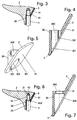
- the sleeve 30 has ribs 301 on the inner wall of a receiving bore 300 in the longitudinal direction, as can be seen in particular from FIGS. 4 and 5 of the drawing.
- the ribs 301 are dimensioned in such a way that the plate 3 with the sleeve 30 can be pushed onto the linkage 4, but remains in the plug-in position by frictional engagement.
- three ribs 301 arranged at the same distance from one another are formed in the longitudinal direction.
- the plate 3 is formed with a contact surface 31 which is shaped in accordance with the surface 10 of the valve body 1, so that the plate 3 with the entire contact surface 31 lies against the valve body 1 in the stop position, as can be seen from FIG. 1 of the drawing .
- the plate 3 is held in the inserted position in the receptacle 20 in a rotationally fixed manner.
- the plate 3 with the sleeve 30 and the ribs 301 can be inexpensively produced in one piece by injection molding.
- the linkage 4 is here with a Approach 40 provided on which a thread 41 is formed which is in a bore 21 of the operating handle 2nd can be screwed in with the appropriate thread.
- a thread 41 is formed which is in a bore 21 of the operating handle 2nd can be screwed in with the appropriate thread.
- End region of a receiving bore 300 an inner bead 302 molded onto your shoulder 400 of the shoulder 40 of the Linkage 4 in the screw-in position in the operating handle 2 comes to rest and the plate 3 with the sleeve 30 on Operating handle 2 and fixed in the recess 20.
Landscapes
- Engineering & Computer Science (AREA)
- Health & Medical Sciences (AREA)
- Life Sciences & Earth Sciences (AREA)
- Hydrology & Water Resources (AREA)
- Public Health (AREA)
- Water Supply & Treatment (AREA)
- Mechanical Engineering (AREA)
- Environmental & Geological Engineering (AREA)
- Mechanically-Actuated Valves (AREA)
- Valve Housings (AREA)
Abstract
Description
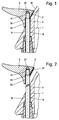
- Fig. 1
- einen Teil eines Armaturenkörpers mit einer Betätigungseinrichtung für ein Ventil im Längsschnitt in der Offenstellung eines Ventils;
- Fig. 2
- den in Fig. 1 gezeigten Teil des Armaturenkörpers mit der Betätigungseinrichtung für ein Ventil, wobei die Betätigungseinrichtung eine Stellung einnimmt, in der das Ventil geschlossen ist;
- Fig. 3
- die in Fig. 1 und 2 gezeigte Betätigungseinrichtung mit einem Teil eines Gestänges und einem Betätigungsgriff mit einer Platte im Längsschnitt;
- Fig. 4
- die in Fig. 3 gezeigte Platte in vergrösserter Darstellung im Längsschnitt;
- Fig. 5
- die in Fig. 4 gezeigte Platte in Perspektivansicht;
- Fig. 6
- ein anderes Ausführungsbeispiel einer Betätigungseinrichtung mit einem Betätigungsgriff und einer Platte im Längsschnitt sowie einem Teil des Gestänges;
- Fig. 7
- die in Fig. 6 gezeigte Platte in vergrösserter Darstellung im Längsschnitt.
In Fig. 1 und 2 ist ein Teil eines Armaturenkörpers 1 für eine sanitäre Einlochmischbatterie dargestellt. In einer Bohrung 11 ist ein Gestänge 4 zur Betätigung eines in der Zeichnung nicht dargestellten Ablaufventils in einem Waschbecken angeordnet. Die Bohrung 11 tritt hierbei aus der Oberfläche 10 des Armaturenkörpers 1 in einem spitzen Winkel aus. Die Oberfläche 10 des Armaturenkörpers 1 ist in der Regel mit Beschichtungen veredelt.
An dem Endbereich des Gestänges 4 ist ein Gewinde 41 ausgebildet, an dem ein Betätigungsgriff 2 befestigt ist. Zu diesem Zweck weist der Betätigungsgriff 2 eine Bohrung 21 auf, in der ein entsprechendes Gewinde zum Gewinde 41 ausgebildet ist. Der Betätigungsgriff 2 ist mit einem Anlagebereich versehen, der sich in der Stecklage parallel zu der Oberfläche 10 des Armaturenkörpers 1 befindet. Der Betätigungsgriff 2 ist hierbei vorzugsweise aus Metall hergestellt.
Um Beschädigungen der Oberfläche 10 durch den Betätigungsgriff 2 zu vermeiden, ist im Anlagebereich eine Platte 3 aus einem die Oberfläche 10 des Armaturenkörpers 1 nicht beschädigenden Werkstoff vorgesehen. Als günstig hat sich erwiesen, die Platte 3 aus Kunststoff herzustellen, vorzugsweise aus Polyäthylen.
Die Platte 3 ist mit einer Anlagefläche 31 ausgebildet, die entsprechend der Oberfläche 10 des Armaturenkörpers 1 geformt ist, so dass die Platte 3 mit der gesamten Anlagefläche 31 in der Anschlagposition am Armaturenkörper 1 anliegt, wie es aus Fig. 1 der Zeichnung zu entnehmen ist. Ausserdem wird mit der im spitzen Winkel an der Platte 3 ausgebildeten Hülse 30 die Platte 3 in der Stecklage in der Aufnahme 20 drehfest gehalten. Die Platte 3 mit der Hülse 30 und den Rippen 301 ist kostengünstig einstückig im Spritzgiessverfahren herstellbar.
Claims (10)
- Betätigungseinrichtung an einem Armaturenkörper (1) für ein Ventil, insbesondere Ablaufventil, mit einem Betätigungsgriff (2) an einem, an der Oberfläche (10) des Armaturenkörpers (1) austretenden, axial begrenzt verschiebbaren Gestänge (4), wobei in einer Axialstellung des Gestänges (4) der Betätigungsgriff (2) mit einem Bereich an der Oberfläche (10) des Armaturenkörpers (1) anliegt, dadurch gekennzeichnet dass der Betätigungsgriff (2) am Anlagebereich mit einer Platte (3) aus einem die Oberfläche (10) des Armaturenkörpers (1) nicht beschädigenden Werkstoff versehen ist, wobei die Platte (3) zur Fixierung in der Stecklage eine koaxial zum Gestänge (4) ausgebildete Hülse (30) aufweist.
- Betätigungseinrichtung nach Anspruch 1, dadurch gekennzeichnet, dass die Hülse (30) von einer Ausnehmung (20) im Betätigungsgriff (2) aufgenommen ist.
- Betätigungseinrichtung nach Anspruch 1 oder 2, dadurch gekennzeichnet, dass die Platte (3) aus Kunststoff im Spritzgiessverfahren hergestellt ist und eine Anlagefläche (31) aufweist, deren Kontur der Kontur der Oberfläche (10) des Armaturenkörpers (1) entspricht.
- Betätigungsvorrichtung nach Anspruch 3, dadurch gekennzeichnet, dass die Platte (3) mit der Hülse (30) aus Polyäthylen (PE) hergestellt ist.
- Betätigungseinrichtung nach wenigstens einem der Ansprüche 1 bis 4, dadurch gekennzeichnet, dass an der Innenwandung einer Aufnahmebohrung (300) der Hülse (30) Rippen (301) ausgebildet sind, die die Platte (3) durch Reibschluss auf dem Gestänge (4) in der Stecklage am Betätigungsgriff (2) halten.
- Betätigungseinrichtung nach Anspruch 5, dadurch gekennzeichnet, dass die Rippen (301) in axialer Richtung in der Aufnahmebohrung (300) in der Hülse (30) ausgebildet sind.
- Betätigungseinrichtung nach Anspruch 6, dadurch gekennzeichnet, dass an der Innenwandung der Aufnahmebohrung (300) drei Rippen (301), vorzugsweise im gleichen Abstand zueinander, vorgesehen sind.
- Betätigungseinrichtung nach wenigstens einem der Ansprüche 1 bis 4, dadurch gekennzeichnet, dass an der Hülse (30) ein umlaufender Innenwulst (302) vorgesehen ist, wobei das Gestänge (4) mit einem Ansatz (40) an dem Betätigungsgriff (2) befestigbar ist, derart, dass in der eingesteckten Position eine Schulter (400) des Gestänges (4) an dem Innenwulst (302) zur Anlage gelangt und die Hülse (30) mit der Platte (3) an dem Betätigungsgriff (2) fixiert.
- Betätigungseinrichtung nach wenigstens einem der Ansprüche 1 bis 8, dadurch gekennzeichnet, dass das Gestänge (4) mit Gewinde (41) mit dem Betätigungsgriff (2) verbindbar ist.
- Befestigungseinrichtung nach wenigstens einem der Ansprüche 1 bis 9, dadurch gekennzeichnet, dass die Hülse (30) in einen spitzen Winkel zur Platte (3) ausgebildet ist, so dass die Platte (3) in der Stecklage drehfest gehalten ist.
Applications Claiming Priority (2)
| Application Number | Priority Date | Filing Date | Title |
|---|---|---|---|
| DE1999130218 DE19930218B4 (de) | 1999-06-30 | 1999-06-30 | Betätigungseinrichtung |
| DE19930218 | 1999-06-30 |
Publications (2)
| Publication Number | Publication Date |
|---|---|
| EP1065420A2 true EP1065420A2 (de) | 2001-01-03 |
| EP1065420A3 EP1065420A3 (de) | 2002-05-15 |
Family
ID=7913219
Family Applications (1)
| Application Number | Title | Priority Date | Filing Date |
|---|---|---|---|
| EP00113446A Withdrawn EP1065420A3 (de) | 1999-06-30 | 2000-06-24 | Betätigungseinrichtung |
Country Status (3)
| Country | Link |
|---|---|
| EP (1) | EP1065420A3 (de) |
| DE (1) | DE19930218B4 (de) |
| ES (1) | ES1046681Y (de) |
Cited By (1)
| Publication number | Priority date | Publication date | Assignee | Title |
|---|---|---|---|---|
| EP2113697A3 (de) * | 2008-04-28 | 2010-06-30 | REMER RUBINETTERIE S.p.A. | Wasserhahn-Mischvorrichtung mit mindestens einem zwischen dem Griff und der Wasseraustrittsbaugruppe angeordneten Abstandselement |
Citations (1)
| Publication number | Priority date | Publication date | Assignee | Title |
|---|---|---|---|---|
| DE19723312A1 (de) | 1997-06-04 | 1998-12-10 | Grohe Armaturen Friedrich | Wassserauslaufventilanordnung |
-
1999
- 1999-06-30 DE DE1999130218 patent/DE19930218B4/de not_active Expired - Fee Related
-
2000
- 2000-06-24 EP EP00113446A patent/EP1065420A3/de not_active Withdrawn
- 2000-06-30 ES ES200001782U patent/ES1046681Y/es not_active Expired - Lifetime
Patent Citations (1)
| Publication number | Priority date | Publication date | Assignee | Title |
|---|---|---|---|---|
| DE19723312A1 (de) | 1997-06-04 | 1998-12-10 | Grohe Armaturen Friedrich | Wassserauslaufventilanordnung |
Cited By (1)
| Publication number | Priority date | Publication date | Assignee | Title |
|---|---|---|---|---|
| EP2113697A3 (de) * | 2008-04-28 | 2010-06-30 | REMER RUBINETTERIE S.p.A. | Wasserhahn-Mischvorrichtung mit mindestens einem zwischen dem Griff und der Wasseraustrittsbaugruppe angeordneten Abstandselement |
Also Published As
| Publication number | Publication date |
|---|---|
| ES1046681Y (es) | 2001-06-16 |
| ES1046681U (es) | 2001-01-16 |
| EP1065420A3 (de) | 2002-05-15 |
| DE19930218B4 (de) | 2004-10-07 |
| DE19930218A1 (de) | 2001-01-04 |
Similar Documents
| Publication | Publication Date | Title |
|---|---|---|
| EP1226363B1 (de) | Beschlag zur lösbaren befestigung an einem möbelteil | |
| EP1002907B1 (de) | Sanitärarmatur und Halteelement | |
| DE102004003133A1 (de) | Sanitärarmatur | |
| EP1707692B1 (de) | Sanitärarmatur mit teleskopierbarem Auslaufsystem | |
| EP3591267A1 (de) | Ventiloberteil | |
| DE10106140B4 (de) | Montagewerkzeug für Zentralverschlüsse zum Befestigen von Rädern an einem Kraftfahrzeug | |
| DE202021104030U1 (de) | Befestigungsvorrichtung für Wasserhähne | |
| DE19930218B4 (de) | Betätigungseinrichtung | |
| DE2900812C2 (de) | Schutzkappe für Ablaufventile von Waschbecken, Wannen u.dgl | |
| DE19852122C2 (de) | Anschlusseinrichtung für einen Sanitärgegenstand | |
| EP0973688B1 (de) | Zapfhahn | |
| EP2775047B1 (de) | Zu- und Überlaufarmatur für eine Badewanne | |
| DE3628473C2 (de) | Wandanschlußstück | |
| DE202020104237U1 (de) | Adapter zur Befestigung eines Push-Up-Ablaufventils oder dergleichen in einer Ablaufgarnitur eines Waschbeckens | |
| DE10261798A1 (de) | Sanitärarmatur | |
| EP1967664A2 (de) | Zweiteiliges Waschbecken | |
| EP0982441A2 (de) | Sanitärer Einhebelmischer | |
| EP1039046B1 (de) | Wandhalter | |
| DE8224277U1 (de) | Druckknopf zum Aufdrücken auf einen Bolzen | |
| EP0809339B1 (de) | Elektrisches Installationsgerät | |
| EP0786613B1 (de) | Befestigung eines Betätigungsgriffs an einer Sanitärarmatur | |
| DE19955263C2 (de) | Ventil, insbesondere Thermostatventil für Heizungsanlagen | |
| DE102023135951A1 (de) | Ablaufarmatur mit Schmutzfangsieb, insbesondere für eine Duschwanne | |
| DE2705626A1 (de) | Absperrventil | |
| DE10313397B4 (de) | Spannvorrichtung |
Legal Events
| Date | Code | Title | Description |
|---|---|---|---|
| PUAI | Public reference made under article 153(3) epc to a published international application that has entered the european phase |
Free format text: ORIGINAL CODE: 0009012 |
|
| AK | Designated contracting states |
Kind code of ref document: A2 Designated state(s): AT BE CH CY DE DK ES FI FR GB GR IE IT LI LU MC NL PT SE |
|
| AX | Request for extension of the european patent |
Free format text: AL;LT;LV;MK;RO;SI |
|
| PUAL | Search report despatched |
Free format text: ORIGINAL CODE: 0009013 |
|
| AK | Designated contracting states |
Kind code of ref document: A3 Designated state(s): AT BE CH CY DE DK ES FI FR GB GR IE IT LI LU MC NL PT SE |
|
| AX | Request for extension of the european patent |
Free format text: AL;LT;LV;MK;RO;SI |
|
| AKX | Designation fees paid | ||
| STAA | Information on the status of an ep patent application or granted ep patent |
Free format text: STATUS: THE APPLICATION IS DEEMED TO BE WITHDRAWN |
|
| 18D | Application deemed to be withdrawn |
Effective date: 20021231 |