EP1065446A2 - Keramischer Heizstab und diesen enthaltende Glühkerze und Verfahren zu deren Herstellung - Google Patents
Keramischer Heizstab und diesen enthaltende Glühkerze und Verfahren zu deren Herstellung Download PDFInfo
- Publication number
- EP1065446A2 EP1065446A2 EP00111705A EP00111705A EP1065446A2 EP 1065446 A2 EP1065446 A2 EP 1065446A2 EP 00111705 A EP00111705 A EP 00111705A EP 00111705 A EP00111705 A EP 00111705A EP 1065446 A2 EP1065446 A2 EP 1065446A2
- Authority
- EP
- European Patent Office
- Prior art keywords
- heating element
- heating
- glow plug
- shaped
- area
- Prior art date
- Legal status (The legal status is an assumption and is not a legal conclusion. Google has not performed a legal analysis and makes no representation as to the accuracy of the status listed.)
- Granted
Links
Images


Classifications
-
- F—MECHANICAL ENGINEERING; LIGHTING; HEATING; WEAPONS; BLASTING
- F23—COMBUSTION APPARATUS; COMBUSTION PROCESSES
- F23Q—IGNITION; EXTINGUISHING-DEVICES
- F23Q7/00—Incandescent ignition; Igniters using electrically-produced heat, e.g. lighters for cigarettes; Electrically-heated glowing plugs
-
- F—MECHANICAL ENGINEERING; LIGHTING; HEATING; WEAPONS; BLASTING
- F23—COMBUSTION APPARATUS; COMBUSTION PROCESSES
- F23Q—IGNITION; EXTINGUISHING-DEVICES
- F23Q7/00—Incandescent ignition; Igniters using electrically-produced heat, e.g. lighters for cigarettes; Electrically-heated glowing plugs
- F23Q7/001—Glowing plugs for internal-combustion engines
- F23Q2007/004—Manufacturing or assembling methods
Definitions
- the invention relates to a heating element with a heating element made of conductive ceramic material, glow plugs with a such heating element, as well as processes for their preparation.
- a heating element with a heating element made of electrically conductive Ceramic material according to the preamble of claim 1 is known from DE 4117253 A1.
- the heating section cantilevered at the top of a hollow holder to the outside directed in a glow plug body, one Insulation layer between the the front end area of the Holder of the ceramic heater corresponding conductor sections inserted and firmly fitted there.
- the ladder sections and the insulation layer are a brazing filler metal connected, that of a Cu-Al-Ti alloy consists.
- the object of the invention is to provide a heating element with a Heating element made of electrically conductive ceramic material and Glow plugs with such a heater are available too represent, simple manufacturing process of the heating element to enable mass production while at the same time high functionality and dimensional accuracy as well as compact Design of heating rod or glow plug achievable should be.
- an inventive Heating rod as provided for a glow plug is a conventional outer appearance Shape. It has a heating element 1a, which is U-shaped Component (see Figures 5a and 5b) or as a sleeve-shaped Component (see Figure 6) is formed; this heating element 1a has a U-shaped area in the heating area 11 (see Figures 5a / 5b) or a hemispherical shell Area with integrally adjoining areas 11a and 11b which are rod-shaped (see FIGS. 5a / 5b) or sleeve-shaped (see Figure 6) are formed and also from the same conductive ceramic material 2 exist.
- a heating element 1a which is U-shaped Component (see Figures 5a and 5b) or as a sleeve-shaped Component (see Figure 6) is formed; this heating element 1a has a U-shaped area in the heating area 11 (see Figures 5a / 5b) or a hemispherical shell Area with integrally adjoining areas 11a and
- the heating element 1 a is made of insulating ceramic material on all sides 3 covered and with this, preferably without any another intermediate layer, intimately connected; the isolating Ceramic mass 3 forms the heating element body 1b, in which the heating element 1a is embedded.
- the leads 11a / 11b emerge from the heating element body 1b out and form the contact surfaces 9.
- a Area of the lines 11a or 11b also as a support base for an electronic component 8 may be formed.
- This electronic Component 8 can be used for diagnosis, sensor technology or control of the heating element 1 a serve.
- the sealing surface 10 is for sealing fit in formed the rod glow plug body, not shown.
- the heating element 1a is preferably produced by injection molding, in which an appropriate shape is filled with the conductive ceramic 2. Subsequently the hosed part 1a with insulating ceramic 3 encapsulated. It is particularly advantageous if these work steps in one unit by multi-component injection molding done in two successive steps.
- the conductive ceramic mass is, for example made of a Sialon powder, which with thermosetting resin or thermoplastic compound to a syringe Mass is mixed.
- the molded part made of 2 components is then treated by heat treatment for the Spray process frees the necessary fillers and so too a compact ceramic blank that is ready to fire still mechanically post-processed, for example by grinding can be.
- the heating area 11 can be targeted in the top of the Heating element to be positioned; in the connection area on the other hand, the cross-section increased to be as small as possible there To provide heating power.
- the heater tip area is another embodiment of the invention Heating element shown schematically.
- the heating area 11 in the outward-facing area of the heating element 1a kept free of insulating ceramic 3, so that the conductive Ceramic mass 2 is exposed; this is particularly beneficial, if the heating rod according to the invention for ionization measurement is used. Add to that through this Measure the heating behavior can be improved since the isolating ceramic 3 in this area does not have to be heated. It is particularly advantageous if the conductive ceramic 2 only on the heating rod tip the surface is exposed because of additional insulation for example, with glaze in the cut area more is needed.
- FIG 3 shows a further embodiment of a heating element according to the invention as part of a single-pole Glow plug, the heating element 1a in the heating area 11 is exposed on the surface of the heating element.
- the heating element 1a designed such that the glow current supply into the heating rod tip via a central supply line relatively large cross-section takes place; from the heating rod tip he is on the heating surface 11 on the lateral surface passed to the glow plug body 6, which as Ground connection is used.
- the heating area can cover the entire area Cover surface or in one or more segments be divided, interrupted by insulating ceramic 3 are.
- the electrical connection of the heating element 1a is for example through a pressure contact via a connector 4 lead to the outside.
- the ground connection is executed so that the conductive surface on the sealing surface 10 Ceramic is exposed at least in sections and thereby the electrical connection to the metallic body 6 is produced, via which the heating element 1a to ground contacted, so that there is a single-pole version of a such a candle, used as a glow plug for a diesel engine or can be designed for a heater, results.
- FIG. 4 Another embodiment of an inventive Glow plug is shown schematically in Figure 4.
- the heating element 1a is also in the installation area surrounded in the body 6 with insulating ceramic 3, so that contact with the body 6 is excluded.
- the Connection areas 5 and 7 are with an electronic component 8 connected, with part of the heating element 1a at the same time serves as a carrier for the electronic component 8. With this electronic component 8, the heating element 1a controlled, clocked or switched between glow and measurement mode become.
- the glow plug is on the electronic Component 8 is used for ionization measurement, the heating rod, as described for example in Figure 2, such designed that the conductive at least in one area Ceramic layer 2 on a suitable for the measurement Job is exposed.
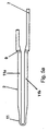
- FIG. 5a is the schematic side view a heating element 1a of a heating rod embodiment according to the invention, reproduced for example according to Figure 1.
- This component is in a first manufacturing stage in Injection molding process and is with an extension of the leg 11b as a carrier 7 for an electronic Component 8 formed.
- This element is used in the subsequent manufacturing stage 2 according to FIG. 5b with an insulating ceramic 3 for final shape with the formation of the heating element 1b overmoulded so that heating element 1a in heating element body 1b is embedded. It is particularly advantageous if this second stage of production by a second injection unit in the same tool is performed after the appropriate Tool slides are pulled and the mold nest for that second manufacturing stage is released.
- the product After overmolding, the product is tempered freed from the fillers; through the finish burn the ceramic components 1 and 2 to a solid uniform Component sintered together. If necessary, the surface of the heating rod, for example on the sealing shoulder Sanding or glazing can be reworked.
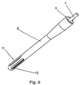
- the heating element 1a can be made of conductive Ceramic mass 2 can also be sleeve-shaped, with this embodiment, a central feed line 7 for the Glow current is provided, which is also preferably from the conductive ceramic mass 2 is formed.
- the contact surface 9 is annular.
- This heating element 1 a can have openings in the heating region 11 Have 12, which on the one hand when finished overmolding insulating ceramic 3 a better filling of the inner cavity of the heating element 1a and on the other hand Reduce the cross-section of the sleeve-shaped conductor; hereby is the electrical resistance of the heating element in this area 1a selectively increase, so that faster heating entry.
Landscapes
- Engineering & Computer Science (AREA)
- Chemical & Material Sciences (AREA)
- Combustion & Propulsion (AREA)
- Mechanical Engineering (AREA)
- General Engineering & Computer Science (AREA)
- Resistance Heating (AREA)
Abstract
Description
Claims (12)
- Heizstab mit einem Heizelement aus elektrisch leitfähigem Keramikmaterial, das einen im Längsschnitt U-förmigen Heizbereich integral anschließend an ein Leiterpaar aufweist, dadurch gekennzeichnet, daß das Heizelement (1a) in einem Heizstabkörper (1b) aus elektrisch isolierender Keramikmasse (3) eingebettet ist, wobei das Heizelement (1a) als U-förmiges Bauteil ausgebildet und durch Spritzgußverfahren hergestellt ist, und unter Ausbildung des Heizstabkörpers (1b) mit einer isolierenden Keramik (3) umspritzt ist.
- Heizstab nach Anspruch 1, dadurch gekennzeichnet, daß das Heizelement (1a) hülsenförmig ausgebildet und durch Spritzgußverfahren hergestellt ist, und unter Ausbildung des Heizstabkörpers (1b) mit einer isolierenden Keramik (3) umspritzt ist.
- Heizstab nach Anspuch 2, dadurch gekennzeichnet, daß im Heizbereich (11) Durchbrüche (12) vorgesehen sind.
- Heizstab nach Anspruch 1, dadurch gekennzeichnet, daß ein Schenkel (11b) des Heizelements (1a) als Anschluß (5) aus dem Heizstabkörper (1b) herausgeführt ist, wobei dieser Bereich oder der gegebenenfalls ebenfalls aus dem Heizstabkörper (1b) herausgeführte Schenkel (11a) als Träger eines elektronischen Bauteils (8) ausgebildet ist.
- Heizstab nach Anspruch 2 oder 3, dadurch gekennzeichnet, daß der Endabschnitt des hülsenförmigen Heizelements 1a als Anschlußrohrabschnitt mit Kontaktfläche 9 ausgebildet ist, während zentrisch durch die Hülse die Zuleitung zur Heizelementspitze geführt ist.
- Heizstab nach einem der vorhergehenden Ansprüche, dadurch gekennzeichnet, daß die U-förmige Biegung des Heizelements (1a) im Heizbereich (11) des Heizstabes auf seiner Außenfläche von isolierender Keramikmasse (3) freigehalten ist.
- Heizstab nach einem der vorhergehenden. Ansprüche, dadurch gekennzeichnet, daß das Heizelement (1a), mit seiner nach außen weisenden Fläche freiliegend, im Heizstabkörper (1b) eingebettet ist, wobei eine mittige, zentrische Stromzuleitung über eine Leitung verhältnismäßig großen Querschnitts, bevorzugt ebenfalls aus elektrisch leitfähiger Keramikmasse (2), vorgesehen ist.
- Stabglühkerze, dadurch gekennzeichnet, daß sie aus einem an sich bekannten Glühkerzenkörper (6) mit einem eingearbeiteten Heizstab nach mindestens einem der Ansprüche 1 bis 7 besteht.
- Stabglühkerze nach Anspruch 8, dadurch gekennzeichnet, daß sie innerhalb des Glühkerzenkörpers (6) auf einer nach innen gerichteten Fläche eines Schenkels (11a/11b) des U-förmigen Heizelements (1a) ein elektronisches Bauteil zur Messung, Regelung oder zum Takten des den Anschlußschenkel durchlaufenden Stroms aufweist.
- Verfahren zur Herstellung eines Heizstabes nach mindestens einem der Ansprüche 1 bis 7, dadurch gekennzeichnet, daß das Heizelement (1a) aus elektrisch leitfähigem Keramikmaterial (2) hergestellt und anschließend durch Umspritzen mit elektrisch isolierender Keramikmasse (3) zu dem Heizstabkörper (1b) und darin eingebetteten Heizelement (1a) umspritzt wird.
- Verfahren nach Anspruch 10, dadurch gekennzeichnet, daß das Verfahren in einem Werkzeug mit zwei Spritzeinheiten im Mehrkomponenten-Spritzgußverfahren durchgeführt wird.
- Verfahren nach Anspruch 10 oder 11, dadurch gekennzeichnet, daß nach dem Umspritzen der gebildete Heizstab temperiert und durch Brennen die Keramikkomponenten zu einem festen, einheitlichen Material zusammengesintert werden.
Applications Claiming Priority (2)
| Application Number | Priority Date | Filing Date | Title |
|---|---|---|---|
| DE19930334 | 1999-07-02 | ||
| DE19930334A DE19930334C2 (de) | 1999-07-02 | 1999-07-02 | Keramischer Heizstab und diesen enthaltende Glühkerze und Verfahren zu dessen Herstellung |
Publications (4)
| Publication Number | Publication Date |
|---|---|
| EP1065446A2 true EP1065446A2 (de) | 2001-01-03 |
| EP1065446A3 EP1065446A3 (de) | 2005-03-02 |
| EP1065446B1 EP1065446B1 (de) | 2008-03-05 |
| EP1065446B2 EP1065446B2 (de) | 2011-06-08 |
Family
ID=7913290
Family Applications (1)
| Application Number | Title | Priority Date | Filing Date |
|---|---|---|---|
| EP00111705A Expired - Lifetime EP1065446B2 (de) | 1999-07-02 | 2000-05-31 | Keramischer Heizstab und diesen enthaltende Glühkerze und Verfahren zu deren Herstellung |
Country Status (7)
| Country | Link |
|---|---|
| US (1) | US6335516B1 (de) |
| EP (1) | EP1065446B2 (de) |
| JP (1) | JP2001033037A (de) |
| KR (1) | KR100588004B1 (de) |
| AT (1) | ATE388375T1 (de) |
| DE (2) | DE19930334C2 (de) |
| ES (1) | ES2298108T3 (de) |
Cited By (3)
| Publication number | Priority date | Publication date | Assignee | Title |
|---|---|---|---|---|
| WO2002061338A1 (de) * | 2001-01-29 | 2002-08-08 | Robert Bosch Gmbh | Verfahren zur herstellung eines startelementes |
| WO2003040623A1 (de) * | 2000-10-27 | 2003-05-15 | Robert Bosch Gmbh | Stiftheizer |
| EP1734304B1 (de) * | 2004-04-07 | 2016-12-14 | Ngk Spark Plug Co., Ltd. | Keramische heizvorrichtung und herstellungsverfahren dafür sowie die keramische heizvorrichtung verwendende glühkerze |
Families Citing this family (18)
| Publication number | Priority date | Publication date | Assignee | Title |
|---|---|---|---|---|
| DE10030924A1 (de) * | 2000-06-24 | 2002-01-03 | Bosch Gmbh Robert | Glühstiftkerze |
| DE10117641C2 (de) * | 2001-04-09 | 2003-02-27 | Beru Ag | Stabglühkerze |
| DE10136596B4 (de) * | 2001-07-30 | 2005-09-15 | Beru Ag | Verfahren zur Verbindung eines stabförmigen Heizelements mit einem rohrförmigen Gehäuse einer Glühkerze und durch dieses Verfahren hergestellte Glühkerze |
| JP3870859B2 (ja) * | 2001-10-16 | 2007-01-24 | 株式会社デンソー | グロープラグ |
| DE10155230C5 (de) * | 2001-11-09 | 2006-07-13 | Robert Bosch Gmbh | Stiftheizer in einer Glühstiftkerze und Glühstiftkerze |
| JP3886449B2 (ja) * | 2002-12-26 | 2007-02-28 | 日本特殊陶業株式会社 | グロープラグ及びグロープラグの取付け構造 |
| DE10353972B4 (de) * | 2003-11-19 | 2006-03-16 | Beru Ag | Verfahren zum Herstellen von keramischen Glühkerzen |
| DE10353973B4 (de) * | 2003-11-19 | 2006-08-17 | Beru Ag | Verfahren zum Herstellen eines keramischen Glühstiftes für eine keramische Glühkerze |
| DE102004033153B4 (de) * | 2004-06-11 | 2007-03-29 | Fraunhofer-Gesellschaft zur Förderung der angewandten Forschung e.V. | Glühkerze und Verfahren zu ihrer Herstellung |
| DE102005030208A1 (de) * | 2005-06-29 | 2007-01-25 | Robert Bosch Gmbh | Glühstiftkerze |
| DE102006016566B4 (de) * | 2005-09-22 | 2008-06-12 | Beru Ag | Zusammengesetzter Leiter, insbesondere für Glühkerzen für Dieselmotoren |
| JP2008020176A (ja) * | 2006-06-14 | 2008-01-31 | Ngk Spark Plug Co Ltd | センサ内蔵グロープラグ |
| US8183501B2 (en) * | 2007-12-13 | 2012-05-22 | Delphi Technologies, Inc. | Method for controlling glow plug ignition in a preheater of a hydrocarbon reformer |
| US20100078421A1 (en) * | 2008-10-01 | 2010-04-01 | Federal-Mogul Italy Sr1 | Glow plug adn heater assembly therefor with an improved connection between a central electrode and a heater probe of the heater assembly |
| DE102011050988B4 (de) * | 2011-06-09 | 2016-04-21 | Borgwarner Ludwigsburg Gmbh | Glühkerze |
| DE102011055283B4 (de) * | 2011-11-11 | 2016-06-23 | Borgwarner Ludwigsburg Gmbh | Glühkerze und Verfahren zum Herstellen eines Glühstifts |
| JP5969621B2 (ja) * | 2012-10-29 | 2016-08-17 | 京セラ株式会社 | ヒータおよびこれを備えたグロープラグ |
| CN109341882B (zh) * | 2018-10-19 | 2020-12-01 | 重庆材料研究院有限公司 | 铠装热电偶冷端的转接结构及其制备方法 |
Citations (1)
| Publication number | Priority date | Publication date | Assignee | Title |
|---|---|---|---|---|
| DE4117253A1 (de) | 1990-05-28 | 1991-12-12 | Jidosha Kiki Co | Gluehkerze fuer dieselmotoren |
Family Cites Families (31)
| Publication number | Priority date | Publication date | Assignee | Title |
|---|---|---|---|---|
| US3924777A (en) * | 1974-02-01 | 1975-12-09 | Continental Can Co | Non-detachable easy open flap and tab assembly |
| JPS58150715A (ja) * | 1982-03-02 | 1983-09-07 | Nippon Denso Co Ltd | デイ−ゼルエンジンの予熱栓 |
| JPS61178834A (ja) * | 1985-01-29 | 1986-08-11 | いすゞ自動車株式会社 | 多層樹脂製タンク及びその製造方法 |
| JPS62731A (ja) * | 1985-06-27 | 1987-01-06 | Jidosha Kiki Co Ltd | デイ−ゼルエンジン用グロ−プラグ |
| JPS62175522A (ja) * | 1986-01-27 | 1987-08-01 | Jidosha Kiki Co Ltd | デイ−ゼルエンジン用グロ−プラグ |
| JPS6467330A (en) * | 1987-09-08 | 1989-03-14 | Dainippon Printing Co Ltd | Heat-shrinkable packaging material and its manufacture |
| EP0342341A3 (de) * | 1988-05-17 | 1991-07-24 | American Cyanamid Company | Verfahren zur Herstellung von Antitumor-Antibiotika LL-E33288 Gamma 2 |
| JP2530209B2 (ja) * | 1988-08-01 | 1996-09-04 | 日本特殊陶業株式会社 | セラミックヒ―タの製造法 |
| JPH0220293U (de) * | 1988-07-26 | 1990-02-09 | ||
| DE3924777A1 (de) * | 1988-07-26 | 1990-02-08 | Ngk Spark Plug Co | Keramische heizvorrichtung und verfahren zu deren herstellung |
| CH681186A5 (de) * | 1989-11-09 | 1993-01-29 | Battelle Memorial Institute | |
| JPH03282122A (ja) * | 1990-03-29 | 1991-12-12 | Hitachi Metals Ltd | ディーゼルエンジン用グロープラグの製造方法 |
| JP2845256B2 (ja) † | 1993-03-18 | 1999-01-13 | 株式会社デンソー | セラミックヒータ |
| JP3351573B2 (ja) * | 1993-06-15 | 2002-11-25 | 株式会社デンソー | セラミック発熱体 |
| US5750958A (en) * | 1993-09-20 | 1998-05-12 | Kyocera Corporation | Ceramic glow plug |
| JP3589684B2 (ja) * | 1993-10-07 | 2004-11-17 | 株式会社デンソー | セラミックグロープラグ |
| DE4335292A1 (de) * | 1993-10-15 | 1995-04-20 | Beru Werk Ruprecht Gmbh Co A | Glühkerze |
| US5367994A (en) * | 1993-10-15 | 1994-11-29 | Detroit Diesel Corporation | Method of operating a diesel engine utilizing a continuously powered glow plug |
| JPH0992587A (ja) * | 1995-09-25 | 1997-04-04 | Tdk Corp | セラミック電子部品製造装置 |
| JPH08180732A (ja) * | 1994-12-20 | 1996-07-12 | Dainippon Printing Co Ltd | 耐火絶縁シート |
| DE19506950C2 (de) † | 1995-02-28 | 1998-07-23 | Bosch Gmbh Robert | Glühstiftkerze für Dieselmotoren |
| JPH08264266A (ja) * | 1995-03-27 | 1996-10-11 | Ngk Spark Plug Co Ltd | セラミックヒータ及びセラミックグロープラグ |
| JP3144535B2 (ja) * | 1995-07-20 | 2001-03-12 | 日本特殊陶業株式会社 | セラミックヒータ |
| JP3737845B2 (ja) * | 1995-12-29 | 2006-01-25 | 日本特殊陶業株式会社 | グロープラグ |
| JP3737846B2 (ja) * | 1995-12-29 | 2006-01-25 | 日本特殊陶業株式会社 | グロープラグ |
| JP3796846B2 (ja) * | 1996-09-12 | 2006-07-12 | 株式会社デンソー | グロープラグ |
| DE19703176C2 (de) * | 1997-01-29 | 2003-02-06 | Fraunhofer Ges Forschung | Verfahren zur Herstellung von keramischen oder pulvermetallurgischen Bauteilen |
| JPH10332149A (ja) * | 1997-03-31 | 1998-12-15 | Ngk Spark Plug Co Ltd | セラミックヒータ |
| JPH1134022A (ja) * | 1997-05-20 | 1999-02-09 | Murata Mfg Co Ltd | セラミックグリーンシートの製造装置 |
| JPH11257659A (ja) * | 1998-03-10 | 1999-09-21 | Ngk Spark Plug Co Ltd | セラミックヒータ及びセラミックグロープラグ |
| US6274079B1 (en) * | 1999-06-23 | 2001-08-14 | Robert Bosch Gmbh | Ceramic pin heating element with integrated connector contacts and method for making same |
-
1999
- 1999-07-02 DE DE19930334A patent/DE19930334C2/de not_active Expired - Fee Related
-
2000
- 2000-05-31 EP EP00111705A patent/EP1065446B2/de not_active Expired - Lifetime
- 2000-05-31 AT AT00111705T patent/ATE388375T1/de not_active IP Right Cessation
- 2000-05-31 ES ES00111705T patent/ES2298108T3/es not_active Expired - Lifetime
- 2000-05-31 DE DE50015007T patent/DE50015007D1/de not_active Expired - Lifetime
- 2000-06-30 KR KR1020000036963A patent/KR100588004B1/ko not_active Expired - Fee Related
- 2000-06-30 US US09/608,224 patent/US6335516B1/en not_active Expired - Lifetime
- 2000-07-03 JP JP2000200410A patent/JP2001033037A/ja active Pending
Patent Citations (1)
| Publication number | Priority date | Publication date | Assignee | Title |
|---|---|---|---|---|
| DE4117253A1 (de) | 1990-05-28 | 1991-12-12 | Jidosha Kiki Co | Gluehkerze fuer dieselmotoren |
Cited By (6)
| Publication number | Priority date | Publication date | Assignee | Title |
|---|---|---|---|---|
| WO2003040623A1 (de) * | 2000-10-27 | 2003-05-15 | Robert Bosch Gmbh | Stiftheizer |
| US6710305B2 (en) | 2000-10-27 | 2004-03-23 | Robert Bosch Gmbh | Sheath heater |
| CZ302319B6 (cs) * | 2000-10-27 | 2011-03-09 | Robert Bosch Gmbh | Žhavicí kolík |
| WO2002061338A1 (de) * | 2001-01-29 | 2002-08-08 | Robert Bosch Gmbh | Verfahren zur herstellung eines startelementes |
| US7224110B2 (en) | 2001-01-29 | 2007-05-29 | Robert Bosch Gmbh | Starting element having ceramic component electrostatically coated with a dry glaze |
| EP1734304B1 (de) * | 2004-04-07 | 2016-12-14 | Ngk Spark Plug Co., Ltd. | Keramische heizvorrichtung und herstellungsverfahren dafür sowie die keramische heizvorrichtung verwendende glühkerze |
Also Published As
| Publication number | Publication date |
|---|---|
| JP2001033037A (ja) | 2001-02-09 |
| ATE388375T1 (de) | 2008-03-15 |
| DE19930334A1 (de) | 2001-01-11 |
| EP1065446B1 (de) | 2008-03-05 |
| ES2298108T3 (es) | 2008-05-16 |
| KR20010049674A (ko) | 2001-06-15 |
| EP1065446B2 (de) | 2011-06-08 |
| EP1065446A3 (de) | 2005-03-02 |
| DE19930334C2 (de) | 2003-07-31 |
| DE50015007D1 (de) | 2008-04-17 |
| KR100588004B1 (ko) | 2006-06-08 |
| US6335516B1 (en) | 2002-01-01 |
Similar Documents
| Publication | Publication Date | Title |
|---|---|---|
| EP1065446A2 (de) | Keramischer Heizstab und diesen enthaltende Glühkerze und Verfahren zu deren Herstellung | |
| DE10353972B4 (de) | Verfahren zum Herstellen von keramischen Glühkerzen | |
| EP2348788A1 (de) | Elektrische Heizvorrichtung | |
| EP1050716B1 (de) | Glühkerze und Verfahren zur Herstellung derselben | |
| DE102018101196A1 (de) | Heizpatrone mit Temperatursensor | |
| EP3247941A1 (de) | Glühstiftkerze | |
| DE19852785A1 (de) | Keramische Glühstiftkerze | |
| EP1125475B1 (de) | Keramische glühstiftkerze | |
| DE1415657B2 (de) | Verfahren zur herstellung der isolierkoerper einer elektri schen kupplung | |
| DE19959768A1 (de) | Glühstiftkerze | |
| DE10155230C5 (de) | Stiftheizer in einer Glühstiftkerze und Glühstiftkerze | |
| EP0544071B1 (de) | Lagerachse für eine, eine Beleuchtungseinrichtung aufweisende Fahrzeugsonnenblende | |
| DE3505517C1 (de) | Elektrische Heizeinrichtung, insbesondere für Kunststoff-Spritzdüsen | |
| DE2025757B2 (de) | LeitungsanschluB | |
| DE3212770A1 (de) | Verfahren zum spaltfreien einbau von mittelelektroden in isolierkoerper von zuendkerzen fuer brennkraftmaschinen | |
| DE102015214057B4 (de) | Verfahren zur Herstellung einer Zündkerze mittels einer mit Pulver befüllten Kapsel sowie Zündkerze | |
| DE102020119424B4 (de) | Verfahren zum Herstellen einer Zündkerze | |
| DE10055447B4 (de) | Elektrisch isolierendes Verbindungselement und Verfahren zu seiner Herstellung | |
| DE102019116127B4 (de) | Schleifkontakt und Verfahren zur Herstellung eines Schleifkontakts | |
| DE10128656A1 (de) | Stabglühkerze und Verfahren zu ihrer Herstellung | |
| DE3513283C2 (de) | ||
| DE102019127689B4 (de) | Elektrischer Rohrheizkörper mit Anschlussbolzen und Herstellungsverfahren für elektrische Rohrheizkörper mit Anschlussbolzen | |
| DE19812501C1 (de) | Steckervorrichtung | |
| DE102012205081B4 (de) | Verfahren zur Herstellung einer keramischen Mehrkomponenten-Glühstiftkerze und dazugehöriges Werkzeug | |
| DE2118577A1 (de) | Isolierte elektrische Buchse |
Legal Events
| Date | Code | Title | Description |
|---|---|---|---|
| PUAI | Public reference made under article 153(3) epc to a published international application that has entered the european phase |
Free format text: ORIGINAL CODE: 0009012 |
|
| AK | Designated contracting states |
Kind code of ref document: A2 Designated state(s): AT BE CH CY DE DK ES FI FR GB GR IE IT LI LU MC NL PT SE |
|
| AX | Request for extension of the european patent |
Free format text: AL;LT;LV;MK;RO;SI |
|
| PUAL | Search report despatched |
Free format text: ORIGINAL CODE: 0009013 |
|
| AK | Designated contracting states |
Kind code of ref document: A3 Designated state(s): AT BE CH CY DE DK ES FI FR GB GR IE IT LI LU MC NL PT SE |
|
| AX | Request for extension of the european patent |
Extension state: AL LT LV MK RO SI |
|
| 17P | Request for examination filed |
Effective date: 20050330 |
|
| AKX | Designation fees paid |
Designated state(s): AT BE CH CY DE DK ES FI FR GB GR IE IT LI LU MC NL PT SE |
|
| 17Q | First examination report despatched |
Effective date: 20060130 |
|
| GRAP | Despatch of communication of intention to grant a patent |
Free format text: ORIGINAL CODE: EPIDOSNIGR1 |
|
| GRAS | Grant fee paid |
Free format text: ORIGINAL CODE: EPIDOSNIGR3 |
|
| GRAA | (expected) grant |
Free format text: ORIGINAL CODE: 0009210 |
|
| AK | Designated contracting states |
Kind code of ref document: B1 Designated state(s): AT BE CH CY DE DK ES FI FR GB GR IE IT LI LU MC NL PT SE |
|
| REG | Reference to a national code |
Ref country code: GB Ref legal event code: FG4D Free format text: NOT ENGLISH |
|
| REG | Reference to a national code |
Ref country code: CH Ref legal event code: EP |
|
| REG | Reference to a national code |
Ref country code: IE Ref legal event code: FG4D Free format text: LANGUAGE OF EP DOCUMENT: GERMAN |
|
| REF | Corresponds to: |
Ref document number: 50015007 Country of ref document: DE Date of ref document: 20080417 Kind code of ref document: P |
|
| REG | Reference to a national code |
Ref country code: ES Ref legal event code: FG2A Ref document number: 2298108 Country of ref document: ES Kind code of ref document: T3 |
|
| REG | Reference to a national code |
Ref country code: SE Ref legal event code: TRGR |
|
| PG25 | Lapsed in a contracting state [announced via postgrant information from national office to epo] |
Ref country code: FI Free format text: LAPSE BECAUSE OF FAILURE TO SUBMIT A TRANSLATION OF THE DESCRIPTION OR TO PAY THE FEE WITHIN THE PRESCRIBED TIME-LIMIT Effective date: 20080305 |
|
| ET | Fr: translation filed | ||
| NLV1 | Nl: lapsed or annulled due to failure to fulfill the requirements of art. 29p and 29m of the patents act | ||
| REG | Reference to a national code |
Ref country code: IE Ref legal event code: FD4D |
|
| PG25 | Lapsed in a contracting state [announced via postgrant information from national office to epo] |
Ref country code: NL Free format text: LAPSE BECAUSE OF FAILURE TO SUBMIT A TRANSLATION OF THE DESCRIPTION OR TO PAY THE FEE WITHIN THE PRESCRIBED TIME-LIMIT Effective date: 20080305 Ref country code: PT Free format text: LAPSE BECAUSE OF FAILURE TO SUBMIT A TRANSLATION OF THE DESCRIPTION OR TO PAY THE FEE WITHIN THE PRESCRIBED TIME-LIMIT Effective date: 20080805 |
|
| BERE | Be: lapsed |
Owner name: BERU A.G. Effective date: 20080531 |
|
| PLBI | Opposition filed |
Free format text: ORIGINAL CODE: 0009260 |
|
| PG25 | Lapsed in a contracting state [announced via postgrant information from national office to epo] |
Ref country code: MC Free format text: LAPSE BECAUSE OF NON-PAYMENT OF DUE FEES Effective date: 20080531 |
|
| REG | Reference to a national code |
Ref country code: CH Ref legal event code: PL |
|
| 26 | Opposition filed |
Opponent name: ROBERT BOSCH GMBH ZGM3 SPALDING Effective date: 20081205 |
|
| PLAX | Notice of opposition and request to file observation + time limit sent |
Free format text: ORIGINAL CODE: EPIDOSNOBS2 |
|
| PG25 | Lapsed in a contracting state [announced via postgrant information from national office to epo] |
Ref country code: DK Free format text: LAPSE BECAUSE OF FAILURE TO SUBMIT A TRANSLATION OF THE DESCRIPTION OR TO PAY THE FEE WITHIN THE PRESCRIBED TIME-LIMIT Effective date: 20080305 Ref country code: CH Free format text: LAPSE BECAUSE OF NON-PAYMENT OF DUE FEES Effective date: 20080531 Ref country code: LI Free format text: LAPSE BECAUSE OF NON-PAYMENT OF DUE FEES Effective date: 20080531 Ref country code: IE Free format text: LAPSE BECAUSE OF FAILURE TO SUBMIT A TRANSLATION OF THE DESCRIPTION OR TO PAY THE FEE WITHIN THE PRESCRIBED TIME-LIMIT Effective date: 20080305 |
|
| PG25 | Lapsed in a contracting state [announced via postgrant information from national office to epo] |
Ref country code: BE Free format text: LAPSE BECAUSE OF NON-PAYMENT OF DUE FEES Effective date: 20080531 |
|
| PLBB | Reply of patent proprietor to notice(s) of opposition received |
Free format text: ORIGINAL CODE: EPIDOSNOBS3 |
|
| PGFP | Annual fee paid to national office [announced via postgrant information from national office to epo] |
Ref country code: ES Payment date: 20090529 Year of fee payment: 10 |
|
| PG25 | Lapsed in a contracting state [announced via postgrant information from national office to epo] |
Ref country code: IT Free format text: LAPSE BECAUSE OF NON-PAYMENT OF DUE FEES Effective date: 20080531 |
|
| PGFP | Annual fee paid to national office [announced via postgrant information from national office to epo] |
Ref country code: SE Payment date: 20090513 Year of fee payment: 10 Ref country code: AT Payment date: 20090511 Year of fee payment: 10 |
|
| PG25 | Lapsed in a contracting state [announced via postgrant information from national office to epo] |
Ref country code: CY Free format text: LAPSE BECAUSE OF FAILURE TO SUBMIT A TRANSLATION OF THE DESCRIPTION OR TO PAY THE FEE WITHIN THE PRESCRIBED TIME-LIMIT Effective date: 20080305 |
|
| PG25 | Lapsed in a contracting state [announced via postgrant information from national office to epo] |
Ref country code: LU Free format text: LAPSE BECAUSE OF NON-PAYMENT OF DUE FEES Effective date: 20080531 |
|
| PGFP | Annual fee paid to national office [announced via postgrant information from national office to epo] |
Ref country code: FR Payment date: 20100525 Year of fee payment: 11 |
|
| PG25 | Lapsed in a contracting state [announced via postgrant information from national office to epo] |
Ref country code: GR Free format text: LAPSE BECAUSE OF FAILURE TO SUBMIT A TRANSLATION OF THE DESCRIPTION OR TO PAY THE FEE WITHIN THE PRESCRIBED TIME-LIMIT Effective date: 20080606 |
|
| PGFP | Annual fee paid to national office [announced via postgrant information from national office to epo] |
Ref country code: GB Payment date: 20100513 Year of fee payment: 11 |
|
| PG25 | Lapsed in a contracting state [announced via postgrant information from national office to epo] |
Ref country code: AT Free format text: LAPSE BECAUSE OF NON-PAYMENT OF DUE FEES Effective date: 20100531 |
|
| EUG | Se: european patent has lapsed | ||
| PUAH | Patent maintained in amended form |
Free format text: ORIGINAL CODE: 0009272 |
|
| STAA | Information on the status of an ep patent application or granted ep patent |
Free format text: STATUS: PATENT MAINTAINED AS AMENDED |
|
| 27A | Patent maintained in amended form |
Effective date: 20110608 |
|
| AK | Designated contracting states |
Kind code of ref document: B2 Designated state(s): AT BE CH CY DE DK ES FI FR GB GR IE IT LI LU MC NL PT SE |
|
| PGFP | Annual fee paid to national office [announced via postgrant information from national office to epo] |
Ref country code: IT Payment date: 20090521 Year of fee payment: 10 |
|
| PGRI | Patent reinstated in contracting state [announced from national office to epo] |
Ref country code: IT Effective date: 20110616 |
|
| REG | Reference to a national code |
Ref country code: ES Ref legal event code: FD2A Effective date: 20111219 |
|
| GBPC | Gb: european patent ceased through non-payment of renewal fee |
Effective date: 20110531 |
|
| PG25 | Lapsed in a contracting state [announced via postgrant information from national office to epo] |
Ref country code: ES Free format text: LAPSE BECAUSE OF NON-PAYMENT OF DUE FEES Effective date: 20100601 |
|
| REG | Reference to a national code |
Ref country code: FR Ref legal event code: ST Effective date: 20120131 |
|
| PG25 | Lapsed in a contracting state [announced via postgrant information from national office to epo] |
Ref country code: FR Free format text: LAPSE BECAUSE OF NON-PAYMENT OF DUE FEES Effective date: 20110531 |
|
| PG25 | Lapsed in a contracting state [announced via postgrant information from national office to epo] |
Ref country code: GB Free format text: LAPSE BECAUSE OF NON-PAYMENT OF DUE FEES Effective date: 20110531 |
|
| REG | Reference to a national code |
Ref country code: DE Ref legal event code: R102 Ref document number: 50015007 Country of ref document: DE Effective date: 20110608 |
|
| PG25 | Lapsed in a contracting state [announced via postgrant information from national office to epo] |
Ref country code: SE Free format text: LAPSE BECAUSE OF NON-PAYMENT OF DUE FEES Effective date: 20100601 |
|
| PGRI | Patent reinstated in contracting state [announced from national office to epo] |
Ref country code: IT Effective date: 20110616 |
|
| REG | Reference to a national code |
Ref country code: DE Ref legal event code: R082 Ref document number: 50015007 Country of ref document: DE Representative=s name: DR. RALF KOTITSCHKE, DE Ref country code: DE Ref legal event code: R082 Ref document number: 50015007 Country of ref document: DE Representative=s name: KOTITSCHKE & HEURUNG PARTNERSCHAFT MBB PATENT-, DE |
|
| PGFP | Annual fee paid to national office [announced via postgrant information from national office to epo] |
Ref country code: DE Payment date: 20160530 Year of fee payment: 17 |
|
| REG | Reference to a national code |
Ref country code: DE Ref legal event code: R119 Ref document number: 50015007 Country of ref document: DE |
|
| PG25 | Lapsed in a contracting state [announced via postgrant information from national office to epo] |
Ref country code: DE Free format text: LAPSE BECAUSE OF NON-PAYMENT OF DUE FEES Effective date: 20171201 |