EP1065461B1 - In der Zementherstellung anwendbarer Verbrennungsprozess - Google Patents
In der Zementherstellung anwendbarer Verbrennungsprozess Download PDFInfo
- Publication number
- EP1065461B1 EP1065461B1 EP00401748A EP00401748A EP1065461B1 EP 1065461 B1 EP1065461 B1 EP 1065461B1 EP 00401748 A EP00401748 A EP 00401748A EP 00401748 A EP00401748 A EP 00401748A EP 1065461 B1 EP1065461 B1 EP 1065461B1
- Authority
- EP
- European Patent Office
- Prior art keywords
- fuel
- primary
- process according
- flame
- oxidizer
- Prior art date
- Legal status (The legal status is an assumption and is not a legal conclusion. Google has not performed a legal analysis and makes no representation as to the accuracy of the status listed.)
- Expired - Lifetime
Links
- 238000002485 combustion reaction Methods 0.000 title claims abstract description 37
- 238000004519 manufacturing process Methods 0.000 title description 19
- 239000004568 cement Substances 0.000 title description 11
- 239000000446 fuel Substances 0.000 claims abstract description 116
- 239000007800 oxidant agent Substances 0.000 claims abstract description 25
- 238000002347 injection Methods 0.000 claims abstract description 10
- 239000007924 injection Substances 0.000 claims abstract description 10
- 238000000034 method Methods 0.000 claims description 34
- QVGXLLKOCUKJST-UHFFFAOYSA-N atomic oxygen Chemical compound [O] QVGXLLKOCUKJST-UHFFFAOYSA-N 0.000 claims description 23
- 239000001301 oxygen Substances 0.000 claims description 23
- 229910052760 oxygen Inorganic materials 0.000 claims description 23
- 239000000463 material Substances 0.000 claims description 9
- 238000001354 calcination Methods 0.000 claims description 6
- VNWKTOKETHGBQD-UHFFFAOYSA-N methane Chemical compound C VNWKTOKETHGBQD-UHFFFAOYSA-N 0.000 claims description 4
- XLYOFNOQVPJJNP-UHFFFAOYSA-N water Substances O XLYOFNOQVPJJNP-UHFFFAOYSA-N 0.000 claims description 4
- 239000003345 natural gas Substances 0.000 claims description 2
- ATUOYWHBWRKTHZ-UHFFFAOYSA-N Propane Chemical compound CCC ATUOYWHBWRKTHZ-UHFFFAOYSA-N 0.000 claims 2
- 239000001294 propane Substances 0.000 claims 1
- 230000001590 oxidative effect Effects 0.000 abstract description 5
- 238000011144 upstream manufacturing Methods 0.000 description 5
- 239000002699 waste material Substances 0.000 description 5
- VTYYLEPIZMXCLO-UHFFFAOYSA-L Calcium carbonate Chemical compound [Ca+2].[O-]C([O-])=O VTYYLEPIZMXCLO-UHFFFAOYSA-L 0.000 description 4
- 239000007789 gas Substances 0.000 description 4
- 229910052500 inorganic mineral Inorganic materials 0.000 description 4
- 239000011707 mineral Substances 0.000 description 4
- 239000000203 mixture Substances 0.000 description 4
- 239000002245 particle Substances 0.000 description 4
- 239000002910 solid waste Substances 0.000 description 4
- 238000009841 combustion method Methods 0.000 description 3
- 238000009434 installation Methods 0.000 description 3
- 239000002243 precursor Substances 0.000 description 3
- CURLTUGMZLYLDI-UHFFFAOYSA-N Carbon dioxide Chemical compound O=C=O CURLTUGMZLYLDI-UHFFFAOYSA-N 0.000 description 2
- UQSXHKLRYXJYBZ-UHFFFAOYSA-N Iron oxide Chemical compound [Fe]=O UQSXHKLRYXJYBZ-UHFFFAOYSA-N 0.000 description 2
- VYPSYNLAJGMNEJ-UHFFFAOYSA-N Silicium dioxide Chemical compound O=[Si]=O VYPSYNLAJGMNEJ-UHFFFAOYSA-N 0.000 description 2
- 239000002956 ash Substances 0.000 description 2
- 229910000019 calcium carbonate Inorganic materials 0.000 description 2
- 230000006378 damage Effects 0.000 description 2
- 238000001035 drying Methods 0.000 description 2
- 230000005484 gravity Effects 0.000 description 2
- 238000010438 heat treatment Methods 0.000 description 2
- 239000000047 product Substances 0.000 description 2
- 239000002994 raw material Substances 0.000 description 2
- 238000001179 sorption measurement Methods 0.000 description 2
- OKTJSMMVPCPJKN-UHFFFAOYSA-N Carbon Chemical compound [C] OKTJSMMVPCPJKN-UHFFFAOYSA-N 0.000 description 1
- 239000004215 Carbon black (E152) Substances 0.000 description 1
- UGFAIRIUMAVXCW-UHFFFAOYSA-N Carbon monoxide Chemical compound [O+]#[C-] UGFAIRIUMAVXCW-UHFFFAOYSA-N 0.000 description 1
- MYMOFIZGZYHOMD-UHFFFAOYSA-N Dioxygen Chemical compound O=O MYMOFIZGZYHOMD-UHFFFAOYSA-N 0.000 description 1
- 235000002918 Fraxinus excelsior Nutrition 0.000 description 1
- 206010061218 Inflammation Diseases 0.000 description 1
- 235000019738 Limestone Nutrition 0.000 description 1
- PNEYBMLMFCGWSK-UHFFFAOYSA-N aluminium oxide Inorganic materials [O-2].[O-2].[O-2].[Al+3].[Al+3] PNEYBMLMFCGWSK-UHFFFAOYSA-N 0.000 description 1
- 230000015572 biosynthetic process Effects 0.000 description 1
- 229910052791 calcium Inorganic materials 0.000 description 1
- 239000011575 calcium Substances 0.000 description 1
- -1 calcium aluminates Chemical class 0.000 description 1
- 235000012241 calcium silicate Nutrition 0.000 description 1
- 229910052799 carbon Inorganic materials 0.000 description 1
- 229910002092 carbon dioxide Inorganic materials 0.000 description 1
- 239000001569 carbon dioxide Substances 0.000 description 1
- 229910002091 carbon monoxide Inorganic materials 0.000 description 1
- 150000004649 carbonic acid derivatives Chemical class 0.000 description 1
- 238000006243 chemical reaction Methods 0.000 description 1
- 239000004927 clay Substances 0.000 description 1
- 239000003245 coal Substances 0.000 description 1
- 238000009826 distribution Methods 0.000 description 1
- 230000000694 effects Effects 0.000 description 1
- 239000003517 fume Substances 0.000 description 1
- 239000010763 heavy fuel oil Substances 0.000 description 1
- 229930195733 hydrocarbon Natural products 0.000 description 1
- 150000002430 hydrocarbons Chemical class 0.000 description 1
- 230000004054 inflammatory process Effects 0.000 description 1
- 239000004615 ingredient Substances 0.000 description 1
- 239000013067 intermediate product Substances 0.000 description 1
- 239000006028 limestone Substances 0.000 description 1
- 239000007788 liquid Substances 0.000 description 1
- 239000010808 liquid waste Substances 0.000 description 1
- ZLNQQNXFFQJAID-UHFFFAOYSA-L magnesium carbonate Chemical compound [Mg+2].[O-]C([O-])=O ZLNQQNXFFQJAID-UHFFFAOYSA-L 0.000 description 1
- 239000001095 magnesium carbonate Substances 0.000 description 1
- 229910000021 magnesium carbonate Inorganic materials 0.000 description 1
- 238000002844 melting Methods 0.000 description 1
- 230000008018 melting Effects 0.000 description 1
- 229910052751 metal Inorganic materials 0.000 description 1
- 239000002184 metal Substances 0.000 description 1
- 230000004048 modification Effects 0.000 description 1
- 238000012986 modification Methods 0.000 description 1
- 239000013502 plastic waste Substances 0.000 description 1
- 239000000843 powder Substances 0.000 description 1
- 238000002360 preparation method Methods 0.000 description 1
- 230000009467 reduction Effects 0.000 description 1
- 239000010865 sewage Substances 0.000 description 1
- 239000000377 silicon dioxide Substances 0.000 description 1
- 239000010802 sludge Substances 0.000 description 1
- 239000002002 slurry Substances 0.000 description 1
- 239000000243 solution Substances 0.000 description 1
Images


Classifications
-
- F—MECHANICAL ENGINEERING; LIGHTING; HEATING; WEAPONS; BLASTING
- F27—FURNACES; KILNS; OVENS; RETORTS
- F27B—FURNACES, KILNS, OVENS OR RETORTS IN GENERAL; OPEN SINTERING OR LIKE APPARATUS
- F27B7/00—Rotary-drum furnaces, i.e. horizontal or slightly inclined
- F27B7/20—Details, accessories or equipment specially adapted for rotary-drum furnaces
- F27B7/36—Arrangements of air or gas supply devices
Definitions
- the present invention relates to a combustion method, applicable more particularly to the calcination of a material based on ore in particular the manufacture of cement in which a material is heated in contact with a source of heat essentially created by a flame generated by at least one fuel and at least one oxidizer. This calcination process is integrated into a cement preparation process.
- the invention also relates to the use of the combustion process for heating a charge whether it is for melting a metal, maintain it in temperature, destruction of waste, etc ...
- Clinker is a product that is obtained by baking a material based on ore and in particular clay and limestone.
- the material in the form of powder can be supplied to a rotary kiln, either in dry form (dry process) or in the form of a water-based paste ("slurry") (wet process).
- the composition of clinker is generally carefully controlled in order to obtain the proportions different mineral materials and especially calcium carbonate, silica, alumina, iron oxide and magnesium carbonate.
- the precursor material for the manufacture of clinker first undergoes drying and heating.
- this material undergoes a calcination in which the carbonates of the different minerals are converted into the oxide of these minerals by removal of carbon dioxide. With temperatures still high, minerals thus obtained chemically react with each other to produce mainly calcium silicates and calcium aluminates.
- This last process is called “clinkerization” process and it is performed in the hot zone of a rotary oven. The resulting clinker is then cooled and sprayed then mixed with additional ingredients to form a cement such as Portland type cement.
- Cement manufacturing processes involve many similarities and essential differences between these different processes reside essentially in the method used to dry, preheat or calcine the precursor of clinker.
- the process of clinker manufacturing is almost always the same ie a process in which uses a rotary kiln in which the clinker precursors descend by gravity while hot gases are flowing against the current from of an area in which combustion has taken place.
- Common fuels that burn easily in rotary clinker furnaces are coal, heavy fuel oil, and natural gas. These fuels have a lower calorific value (PCI) having a value between 30 and 45 x 10 6 joules / kg. Heavy fuels can be preheated and atomized into droplets of sizes less than 200 microns with a fraction of their mass transformed into droplets of diameter less than 50 microns. The smallest droplets evaporate quickly, allowing the flame to ignite near the end of the burner.
- PCI calorific value
- the carbon particles are pulverized with a size distribution between 10 and 200 microns.
- the rapid and stable ignition of the combustion is improved by the control of the size but also by the combustible volatile matter released by the particles when they are heated.
- cement manufacturers make continuous efforts to lower the cost of fuels used in the production of clinker and today try to burn in particular liquid or solid waste with low combustible qualities and often lower calorific value (PCI) at 15 x 10 6 joule / kg.
- PCI calorific value
- These bad fuels however, often have a water content greater than 20% by mass, or a large particle size (for example 75% of the mass consisting of particles or droplets larger than 200 microns).
- the problem underlying the invention results from the observation by the inventors that the fuel injected into the furnace and in particular the fuels to low calorific value lower could only participate in combustion before to have traveled a fairly long distance inside the rotary kiln. If the distance the oven is too short, the combustion is of poor quality.
- the flame comprises a primary combustion zone created by the combustion of a first fuel and of a first oxidizer, this primary zone being located near the injection points of the first oxidizer and of the first fuel, as well as a secondary combustion zone located downstream of the primary zone, for the combustion of a second fuel having a lower calorific value (PCI) less than or equal to 15 ⁇ 10 6 J / kg and a second oxidant, the second fuel being preheated by passage into or near the primary flame area.
- PCI calorific value
- the distance of passage of the second fuel in contact of the primary zone flame will be sufficient for at least part of the second fuel has been preheated to a temperature of at least about 400 ° C, preferably about 600 ° C and more preferably 800 ° C.
- the secondary fuel will be a fuel whose lower calorific value (PCI) will be less than 15 x 10 6 joule / kg.
- the secondary fuel may be a fuel whose mass content in water will be greater than or equal to approximately 20% and less than or equal to approximately 95%, preferably less than or equal to 70%.
- the secondary fuel will contain ash in mass proportion greater than 20%.
- the ignition distance defined as being the distance between the injection end of the oxidants and fuels and the start of the combustion zone will be less than 2 m, preferably less than about 1 m.
- the primary flame area will be considered substantially ends when more than about 90% of the primary oxidant has reacted with the primary fuel.
- the energy of the primary flame will be the lowest possible and will represent at most 30% and preferably at most 15% of the energy total brought by the flame.
- the energy of the primary flame will represent approximately between 1% and 10% of the total energy provided by the flame, this primary flame preferably comprising a temperature zone also as high as possible, so as to raise the temperature as quickly as possible secondary fuel on contact.
- the primary fuel will be a fuel preferably having a PCI greater than 30 x 10 6 joule / kg, that is to say a fuel which ignites easily.
- this fuel having good qualities a fuel having a low lower calorific value or a fuel having poor ignition qualities as defined above in proportions such that a primary flame having the required temperature qualities and in particular having a temperature preferably greater than 800 ° C. and more preferably greater than 1000 ° C.
- the primary oxidizer will be an oxidizer which will contain more than 21% of oxygen and preferably more than 35% of oxygen, more preferably more than 50% of oxygen and even more preferably will be industrially pure oxygen, that is to say of oxygen comprising more than about 88% by volume of oxygen such as the oxygen produced by oxygen production systems by adsorption such as VSA (Vaccum Swing Adsorption System) and may also consist of oxygen of cryogenic quality, that is to say having a purity often greater than 98%, possibly pure or mixed with air.
- VSA Vacum Swing Adsorption System
- the secondary fuel has already been described above, while the secondary oxidizer will preferably be air and in particular air which is usually used in the burner installed in cement kilns (still called primary air and / or secondary air).
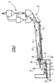
- the raw material from zone 1 is sent to the pre-calcination zone 3 (or according to some variant a Lepol type exchanger) in which the temperature of the raw material gradually heats up against current of hot gases flowing from left to right in the figure.
- the pre-calcination zone 3 or according to some variant a Lepol type exchanger in which the temperature of the raw material gradually heats up against current of hot gases flowing from left to right in the figure.
- FIG 2 is shown a detail view of the flame (12) shown in Figure 1.
- the flame spreads over a large length of the rotary kiln (4) and the start of combustion actually begins a certain distance from the end of the burner (8), the visible non-combustion zone between the end of the burner and the start of the flame being represented by the area (13).
- the primary air and main fuel are injected into the burner while secondary air is injected on the sides (according to the prior art).
- Primary air is injected at a temperature of around 100 ° C, the secondary air has a temperature often between 500 and 900 ° C, while the flame temperature in its hottest part is around 1900 ° C at least.
- the length of the flame in such a rotary kiln is typically 4 to 7 times the diameter of the rotary kiln (4).
- FIGS. 3 A and 3 B the same figures show reference that in the previous figures the flames of the prior art, in the case where the ignition distance (D) represented by area (13) is correct for ensure good combustion, this distance (D) generally being less than 1 meter ( Figure 3a) while in Figure 3b is typically shown a flame degraded, that is to say that the zone (13) extends over a length D, which is unacceptable, which is in the range of 2 to 3 meters or more. Not only this ignition distance is too large but the ignition position, i.e. the tip of the non-inflamed area can fluctuate greatly and there are risk of flame release. Typically the injection of poor quality in an existing flame of the prior art as described above, leads to a degraded flame as shown in this figure 3b this which is unacceptable both from the point of view of combustion and from the point of view of installation security.
- FIG. 4 shows a first solution according to the invention in which the hot oxy-fuel flame is located around the jet of poor quality secondary fuel, i.e. surrounds it.
- the secondary fuel is injected in (24), while around it through the concentric orifice (23) is injected with the mixture of oxygen and first fuel so as to create a flame hot enough to preheat as it has
- the fuel injected through the orifice (24) of poor quality has been described above.
- the flame develops with in the center in the upstream flame area an area (25) in which the second fuel is preheated in contact with the generally oxy-combustible, hot flame, which develops in area (26) around poor quality fuel, while that a second downstream combustion zone develops substantially beyond the vertical line (40) shown in the figure, generally when about more than 90 % of the oxidizer, i.e. the oxygen used in the hot flame (26), has already reacted with the first fuel (usually of good quality) to create the hot flame which preheats the second fuel.
- Downstream from line (40) we finds the second flame combustion zone resulting essentially from the combustion of the second fuel (of poor quality) with the surrounding air, i.e.
- the entire flame (29) thus thus comprises a rear part upstream of the line (40), essentially formed by a short oxy-fuel flame which preheats the second fuel and a downstream part (27) in which produces the main combustion according to the invention, fuel from poor quality with air, combustion which can be carried out under conditions correct thanks to the preheating according to the invention of poor fuel quality in the upstream part of the flame.
- FIG. 5 shows another variant of the invention, in which the flame which heats the poor quality fuel (25) is injected centrally in the injection system while the bad fuel quality to be heated surrounds this oxy-fuel flame injected through the orifice (23).
- the other elements remain similar to those described in Figure 4, with the same operating principle, namely in the upstream zone preheating of the poor quality fuel which thus reaches the downstream part with a temperature generally preferably greater than or equal to 1000 ° C. which burns completely correctly with primary and / or secondary air from the annular cavities (22) and / or (21).
- the second fuel of poor quality which should be preheated by the flame preferably oxygen and first fuel, will be injected into it or outside of it at a speed which will preferably not exceed 50 meters / s and more preferably which will not exceed 20 meters / s.
- the speeds injection of this second fuel to be preheated of the order of 10 meters / s were suitable, particularly in the case of low PCI fuels or aqueous fuels such as sludge from sewage treatment plants, etc.
- this solid waste such as carpet waste or plastic waste being generally made up of relatively coarse pieces and injected into speeds which are on the contrary high, for example of the order of 200 meters / s, of so as to be projected as far upstream as possible from the "clinkerization" zone of the clinker and can then be pyrolyzed and thus be associated with the formation of the clinker.
- FIG. 6 represents an alternative embodiment of the invention corresponding to a modification of an existing burner on an oven (32).
- All of the system (31) comprises in its lower part the existing burner (32) and in its upper part the whole added to implement the method according to the invention.
- the fuel which possibly includes waste in particular solid waste is injected through the orifice (34), pneumatically using air primary while secondary air is injected into the annular duct (33) so as to produce the combustion system according to the prior art.
- the second fuel to be preheated (35) is located in the center of an injected flame by the annular cover (36) preferably constituted as described above, of oxygen and a first fuel so as to preheat this second combustible.
- This second fuel is preferably constituted as indicated above of a pulverulent or liquid fuel which needs to be preheated before to be able to react in the secondary combustion zone of the flame with air secondary especially not having reacted with the flame (33 - 34).
- the elements of this flame (35 - 36) meets the elements of the aerocombustible flame by gravity.
Landscapes
- Engineering & Computer Science (AREA)
- Mechanical Engineering (AREA)
- General Engineering & Computer Science (AREA)
- Curing Cements, Concrete, And Artificial Stone (AREA)
- Muffle Furnaces And Rotary Kilns (AREA)
- Furnace Details (AREA)
Claims (20)
- Kalzinationsverfahren eines auf Mineralien basierenden Materiales, bei welchem das Material durch Kontakt mit einer Wärmequelle aufgeheizt wird, die im Wesentlichen durch eine Flamme geschaffen wird, die durch mindestens einen Brennstoff und mindestens einen verbrennungsfördernden Stoff erzeugt wird, wobei die Flamme einen primären Verbrennungsbereich umfasst, der durch die Verbrennung eines ersten Brennstoffes, primärer Brennstoff genannt, und eines ersten verbrennungsfördernden Stoffes geschaffen wird, wobei dieser primäre Bereich in der Nähe der Einpressungsstellen des ersten verbrennungsfördernden Stoffes und des ersten Brennstoffes liegt, als auch einen sekundären Verbrennungsbereich, der stromabwärts des primären Bereiches angeordnet ist und durch die Verbrennung eines Brennstoffes, sekundärer Brennstoff genannt, und eines zweiten verbrennungsfördernden Stoffes geschaffen wird, wobei der sekundäre Brennstoff beim Durchgang durch den primären Bereich der Flamme vorgeheizt wird, dadurch gekennzeichnet, dass der sekundäre Brennstoff einen unteren Heizwert (PCI) von weniger oder gleich 15 x 106 Joule/kg aufweist.
- Verfahren nach Anspruch 1, dadurch gekennzeichnet dass die Durchgangsstrecke des sekundären Brennstoffes im Kontakt mit der Flamme des primären Bereiches ausreichend ist, damit mindestens ein Teil des sekundären Brennstoffes auf eine Temperatur von mindestens 400 °C vorgeheizt worden ist.
- Verfahren nach Anspruch 2, dadurch gekennzeichnet, dass die Durchgangsstrecke des sekundären Brennstoffes im Kontakt mit der Flamme des primären Bereiches ausreichend ist, damit mindestens ein Teil des sekundären Brennstoffes auf eine Temperatur von mindestens 600 °C und vorzugsweise 800 °C vorgeheizt worden ist.
- Verfahren nach Anspruch 2, dadurch gekennzeichnet, dass die Durchgangsstrecke des sekundären Brennstoffes im Kontakt mit der Flamme des primären Bereiches ausreichend ist, damit mindestens ein Teil des sekundären Brennstoffes auf eine Temperatur von mindestens 1000 °C vorgeheizt worden ist.
- Verfahren nach einem der Ansprüche 1 bis 4, dadurch gekennzeichnet, dass der sekundäre Brennstoff ein Brennstoff ist, dessen Wassergehalt mehr oder gleich 20 Gew.-%, und weniger oder gleich 95 Gew.-%, vorzugsweise 70 Gew.-%, beträgt.
- Verfahren nach einem der Ansprüche 1 bis 5, dadurch gekennzeichnet, dass der sekundäre Brennstoff ein Brennstoff ist, der Verbrennungsrückstände in Proportionen von mehr als 20 Gew.-% enthält.
- Verfahren nach einem der Ansprüche 1 bis 6, dadurch gekennzeichnet, dass die Entzündungsstrecke zwischen der Einpressungsstelle des verbrennungsfördernden Stoffes oder des Brennstoffes und dem Beginn der sekundären Flamme weniger als zwei Meter, und vorzugsweise weniger als ein Meter beträgt.
- Verfahren nach einem der Ansprüche 1 bis 7, dadurch gekennzeichnet, dass der sekundäre Brennstoff mehrere sekundäre Brennstoffe enthält und 0 Vol.-% bis 50 Vol.-% an Brennstoff enthält, der mit dem primären Brennstoff identisch ist.
- Verfahren nach einem der Ansprüche 1 bis 7, dadurch gekennzeichnet, dass der primäre Brennstoff 0 Vol.-% bis 100 Vol.-% an Brennstoff umfasst, der als sekundärer Brennstoff verwendet wird.
- Verfahren nach einem der Ansprüche 1 bis 9, dadurch gekennzeichnet, dass der sekundäre Verbrennungsbereich in einer Entfernung nach der Einpressung der verbrennungsfördernden Stoffe und der Brennstoffe beginnt, wenn mehr als 90 Vol.-% des primären verbrennungsfördernden Stoffes mit dem primären Brennstoff reagiert hat.
- Verfahren nach einem der Ansprüche 1 bis 10, dadurch gekennzeichnet, dass die Energie der primären Flamme mehr als 30%, vorzugsweise mehr als 15% der gesamten durch die Flamme eingebrachten Energie darstellt.
- Verfahren nach einem der Ansprüche 1 bis 11, dadurch gekennzeichnet, dass die Energie der primären Flamme zwischen 1% und 10% der gesamten durch die Flamme eingebrachten Energie darstellt.
- Verfahren nach einem der Ansprüche 1 bis 12, dadurch gekennzeichnet, dass der primäre Brennstoff unter Erdgas und/oder Propangas ausgewählt wird.
- Verfahren nach einem der Ansprüche 1 bis 13, dadurch gekennzeichnet, dass der primäre verbrennungsfördernde Stoff aus Luft besteht, die mit Sauerstoff angereichert ist und mehr als 21 Vol.-% Sauerstoff umfasst.
- Verfahren nach Anspruch 14, dadurch gekennzeichnet, dass der primäre verbrennungsfördernde Stoff mehr als 50 Vol.-% Sauerstoff, vorzugsweise mehr als 88 Vol.-% Sauerstoff, umfasst.
- Verfahren nach Anspruch 15, dadurch gekennzeichnet, dass der primäre verbrennungsfördernde Stoff mehr als 98 Vol.-% Sauerstoff umfasst.
- Verfahren nach einem der Ansprüche 1 bis 16, dadurch gekennzeichnet, dass der sekundäre verbrennungsfördernde Stoff hauptsächlich aus Luft besteht.
- Verfahren nach einem der Ansprüche 1 bis 17, dadurch gekennzeichnet, da4ss der primäre verbrennungsfördernde Stoff eine Sauerstoffkonzentration aufweist, die höher ist als die Sauerstoffkonzentration des sekundären verbrennungsfördernden Stoffes.
- Verfahren nach einem der vorhergehenden Ansprüche, dadurch gekennzeichnet, dass der zweite Brennstoff mit einer Geschwindigkeit eingepresst wird, die nicht höher als 50 m/s ist, die vorzugsweise nicht höher als eine Geschwindigkeit von 20 m/s ist.
- Verfahren nach Anspruch 19, dadurch gekennzeichnet, dass der zweite Brennstoff mit einer Geschwindigkeit in der Größenordnung von 10 m/s eingepresst wird.
Applications Claiming Priority (2)
| Application Number | Priority Date | Filing Date | Title |
|---|---|---|---|
| FR9908562A FR2795808B1 (fr) | 1999-07-02 | 1999-07-02 | Procede de combustion, applicable a la fabrication de ciment |
| FR9908562 | 1999-07-02 |
Publications (2)
| Publication Number | Publication Date |
|---|---|
| EP1065461A1 EP1065461A1 (de) | 2001-01-03 |
| EP1065461B1 true EP1065461B1 (de) | 2004-03-17 |
Family
ID=9547648
Family Applications (1)
| Application Number | Title | Priority Date | Filing Date |
|---|---|---|---|
| EP00401748A Expired - Lifetime EP1065461B1 (de) | 1999-07-02 | 2000-06-20 | In der Zementherstellung anwendbarer Verbrennungsprozess |
Country Status (9)
| Country | Link |
|---|---|
| US (1) | US6375456B1 (de) |
| EP (1) | EP1065461B1 (de) |
| JP (1) | JP4642972B2 (de) |
| CN (1) | CN1208575C (de) |
| AT (1) | ATE262150T1 (de) |
| CA (1) | CA2312576C (de) |
| DE (1) | DE60008970T2 (de) |
| ES (1) | ES2216834T3 (de) |
| FR (1) | FR2795808B1 (de) |
Cited By (3)
| Publication number | Priority date | Publication date | Assignee | Title |
|---|---|---|---|---|
| DE102011015317A1 (de) | 2011-03-28 | 2012-10-04 | Air Liquide Deutschland Gmbh | Verfahren und Vorrichtung zum Betreiben eines Ofens |
| EP2717007A1 (de) | 2012-10-08 | 2014-04-09 | Air Liquide Deutschland GmbH | Verfahren und Vorrichtung zur Verbesserung der Verbrennung von sekundärem Brennstoff in einem Drehrohrofen |
| WO2014056804A1 (en) | 2012-10-08 | 2014-04-17 | L'air Liquide,Societe Anonyme Pour L'etude Et L'exploitation Des Procedes Georges Claude | Process and apparatus for improving the combustion of secondary fuel in a rotary kiln and process for retrofitting a rotary kiln with a burner assembly |
Families Citing this family (14)
| Publication number | Priority date | Publication date | Assignee | Title |
|---|---|---|---|---|
| JP4947249B2 (ja) * | 2004-02-16 | 2012-06-06 | 三菱マテリアル株式会社 | ロータリーキルンを用いた可燃性廃棄物の処理方法 |
| JP4964185B2 (ja) * | 2004-02-26 | 2012-06-27 | 太平洋セメント株式会社 | セメントクリンカの製造方法 |
| FR2889579B1 (fr) * | 2005-08-03 | 2007-09-14 | Air Liquide | Procede de calcination d'un materiau a faible emission de nox |
| JP4777044B2 (ja) * | 2005-11-04 | 2011-09-21 | 太平洋セメント株式会社 | セメント製造装置及びセメント製造方法 |
| US7452203B2 (en) * | 2006-10-16 | 2008-11-18 | Praxair Technology, Inc. | Stratified staging in kilns |
| JP4926781B2 (ja) * | 2007-03-27 | 2012-05-09 | 住友大阪セメント株式会社 | 高含水率廃棄物の処理方法及び処理装置 |
| US8684956B2 (en) | 2009-07-30 | 2014-04-01 | Mcneil-Ppc, Inc. | Oral care device |
| US20120315590A1 (en) * | 2011-06-10 | 2012-12-13 | Hansen Eric R | Method and apparatus for reducing nox emissions in rotary kilns by sncr |
| EP2626628B1 (de) * | 2012-02-09 | 2014-04-09 | Linde Aktiengesellschaft | Befeuerung eines Industrieofens und zugehöriger Brenner |
| WO2014053190A1 (en) * | 2012-10-05 | 2014-04-10 | Air Liquide Brasil Ltda | Lost wax process and calcination furnace for same |
| AU2014326102B2 (en) * | 2013-09-30 | 2017-06-29 | Mitsubishi Ube Cement Corporation | Method for operating cement production facility |
| JP6417221B2 (ja) * | 2015-01-09 | 2018-10-31 | 太平洋セメント株式会社 | セメント焼成装置及び可燃性廃棄物の処理方法 |
| CN107191950B (zh) * | 2017-05-31 | 2019-01-11 | 长沙紫宸科技开发有限公司 | 一种废塑料悬浮催化裂解和催化氧化无焰燃烧方法 |
| WO2024052590A1 (en) * | 2022-09-08 | 2024-03-14 | Metso Metals Oy | Fluidized bed calcination with gas mixture comprising hydrogen |
Family Cites Families (18)
| Publication number | Priority date | Publication date | Assignee | Title |
|---|---|---|---|---|
| DE570045C (de) * | 1928-05-02 | 1933-02-10 | Pierre Jules Justinien Andrieu | Verfahren und Brenner zur Verbrennung gasfoermiger, fluessiger oder staubfoermiger Brennstoffe, insbesondere zur Beheizung von Zementdrehrohroefen |
| US2654592A (en) * | 1950-10-25 | 1953-10-06 | Foamrock Corp | Furnace |
| DE1145082B (de) * | 1960-05-07 | 1963-03-07 | Rheinische Kalksteinwerke | Verfahren zum Betrieb eines Drehrohrofens zum Brennen von Kalkstein, Dolomit oder Magnesit |
| US3302938A (en) | 1965-01-25 | 1967-02-07 | Bendy Engineering Company | Cement production in a rotary kiln |
| US3404199A (en) | 1965-10-01 | 1968-10-01 | Rheinische Kalkstein Werke G M | Heating process in a rotary kiln |
| DE2052646A1 (en) * | 1970-10-27 | 1972-05-04 | Fetok Gmbh | Rotary shaft cement burning kiln - with two different flame jet length fuel oil burners |
| JPS5722908B2 (de) | 1973-04-11 | 1982-05-15 | ||
| US3890084A (en) * | 1973-09-26 | 1975-06-17 | Coen Co | Method for reducing burner exhaust emissions |
| JPS5418686B2 (de) * | 1975-01-14 | 1979-07-10 | ||
| US4496306A (en) * | 1978-06-09 | 1985-01-29 | Hitachi Shipbuilding & Engineering Co., Ltd. | Multi-stage combustion method for inhibiting formation of nitrogen oxides |
| JPS5727954A (en) * | 1980-07-24 | 1982-02-15 | Babcock Hitachi Kk | Cement burning process |
| NL8902963A (nl) * | 1989-12-01 | 1991-07-01 | Int Flame Research Foundation | Werkwijze voor het verbranden van brandstof met een laag nox-gehalte in de verbrandingsgassen door middel van getrapte brandstoftoevoer en brander te gebruiken daarbij. |
| US5007823A (en) | 1989-12-01 | 1991-04-16 | Air Products And Chemicals, Inc. | Dust recycling to rotary kilns |
| US5769624A (en) * | 1992-09-18 | 1998-06-23 | Luminis Pty. Ltd | Variable flame burner configuration |
| US5421880C1 (en) * | 1994-01-14 | 2001-06-05 | Texas Industries Inc | Method and apparatus for using steel slag in cement clinker production |
| US5572938A (en) | 1995-02-13 | 1996-11-12 | Praxair Technology, Inc. | Oxygen lancing for production of cement clinker |
| US5580237A (en) | 1995-03-09 | 1996-12-03 | Praxair Technology, Inc. | Oxidant lancing nozzle |
| JP3285463B2 (ja) * | 1995-04-14 | 2002-05-27 | 吉澤石灰工業株式会社 | ロータリーキルンにおける廃プラスチックの燃焼方法 |
-
1999
- 1999-07-02 FR FR9908562A patent/FR2795808B1/fr not_active Expired - Fee Related
-
2000
- 2000-06-20 EP EP00401748A patent/EP1065461B1/de not_active Expired - Lifetime
- 2000-06-20 ES ES00401748T patent/ES2216834T3/es not_active Expired - Lifetime
- 2000-06-20 DE DE60008970T patent/DE60008970T2/de not_active Expired - Lifetime
- 2000-06-20 AT AT00401748T patent/ATE262150T1/de not_active IP Right Cessation
- 2000-06-22 US US09/599,215 patent/US6375456B1/en not_active Expired - Lifetime
- 2000-06-27 CA CA002312576A patent/CA2312576C/en not_active Expired - Lifetime
- 2000-06-30 CN CN00119915.3A patent/CN1208575C/zh not_active Expired - Fee Related
- 2000-06-30 JP JP2000198792A patent/JP4642972B2/ja not_active Expired - Lifetime
Cited By (4)
| Publication number | Priority date | Publication date | Assignee | Title |
|---|---|---|---|---|
| DE102011015317A1 (de) | 2011-03-28 | 2012-10-04 | Air Liquide Deutschland Gmbh | Verfahren und Vorrichtung zum Betreiben eines Ofens |
| WO2012130858A1 (en) | 2011-03-28 | 2012-10-04 | L'air Liquide Societe Anonyme Pour L'etude Et L'exploitation Des Procedes Georges Claude | Method and apparatus for operating a furnace |
| EP2717007A1 (de) | 2012-10-08 | 2014-04-09 | Air Liquide Deutschland GmbH | Verfahren und Vorrichtung zur Verbesserung der Verbrennung von sekundärem Brennstoff in einem Drehrohrofen |
| WO2014056804A1 (en) | 2012-10-08 | 2014-04-17 | L'air Liquide,Societe Anonyme Pour L'etude Et L'exploitation Des Procedes Georges Claude | Process and apparatus for improving the combustion of secondary fuel in a rotary kiln and process for retrofitting a rotary kiln with a burner assembly |
Also Published As
| Publication number | Publication date |
|---|---|
| CA2312576C (en) | 2009-08-18 |
| US6375456B1 (en) | 2002-04-23 |
| CN1208575C (zh) | 2005-06-29 |
| ES2216834T3 (es) | 2004-11-01 |
| FR2795808A1 (fr) | 2001-01-05 |
| EP1065461A1 (de) | 2001-01-03 |
| JP2001064049A (ja) | 2001-03-13 |
| DE60008970D1 (de) | 2004-04-22 |
| DE60008970T2 (de) | 2005-02-10 |
| ATE262150T1 (de) | 2004-04-15 |
| FR2795808B1 (fr) | 2001-09-14 |
| JP4642972B2 (ja) | 2011-03-02 |
| CN1290668A (zh) | 2001-04-11 |
| CA2312576A1 (en) | 2001-01-02 |
Similar Documents
| Publication | Publication Date | Title |
|---|---|---|
| EP1065461B1 (de) | In der Zementherstellung anwendbarer Verbrennungsprozess | |
| EP2304363B2 (de) | Verfahren zur herstellung von zementklinkern in einem werk und werk zur herstellung von zementklinkern | |
| EP0033285B1 (de) | Vorrichtung zum Mischen mit Turbulenz von Gas enthaltenden Fluida und festen Partikeln | |
| EP3724144B1 (de) | Klinkerproduktionsanlage und verfahren zur klinkerherstellung in einer solchen anlage | |
| BE1003543A4 (fr) | Procede de fabrication de ciment. | |
| EP1807375A2 (de) | Vorrichtung und verfahren zur calcinierung einer ein hydraulisches bindemittel enthaltenden mineralbeladung | |
| EP1065460A1 (de) | Kalzinierungsverfahren für Materialen auf Basis von Erzen | |
| FR2591913A1 (fr) | Procede de traitement thermique de matieres particulaires fines | |
| WO2009122065A2 (fr) | Procede de fabrication d'un clinker sulfo-alumineux ou sulfo-alumineux-belitique et installation correspondante | |
| FR2757845A1 (fr) | Procede pour ameliorer le profil thermique des fours de verre et four de fusion de verre pour sa mise en oeuvre | |
| FR2691790A1 (fr) | Installation et procédé de précalcination de matières minérales quelconques. | |
| EP1913321B1 (de) | VERFAHREN ZUR KALZINIERUNG EINES MATERIALS MIT GERINGEN NOx-EMISSIONEN | |
| BE1023896B1 (fr) | Procede de combustion de combustible dans une chambre de combustion tubulaire | |
| EP0182697B1 (de) | Verfahren und Vorrichtung zur thermischen Behandlung, verwendbar bei der Herstellung eines hydraulischen Bindemittels, enhaltend eine Nachverbrennungsstufe | |
| EP1388526B1 (de) | Veerfahren zur Herstellung von Zement, insbesondere zur Reduktion von NOx-Emissionen | |
| EP2242975A2 (de) | Verfahren zur erhitzung eines mineralrohstoffes in einem tunnelofen | |
| EP3813992B1 (de) | Sauerstoffanreicherung und verbrennung eines brennstoffs in form von festpartikeln, die von einem trägergas befördert werden | |
| FR2969267A1 (fr) | Procede de fusion a chargement discontinu | |
| WO2022180326A1 (fr) | Ensemble de calcination pour la decarbonatation des matieres crues et procédé de production de clinker | |
| CN107250065A (zh) | 制造矿物熔体的方法和装置 | |
| BE499029A (de) | ||
| BE435860A (de) | ||
| BE420338A (de) |
Legal Events
| Date | Code | Title | Description |
|---|---|---|---|
| PUAI | Public reference made under article 153(3) epc to a published international application that has entered the european phase |
Free format text: ORIGINAL CODE: 0009012 |
|
| AK | Designated contracting states |
Kind code of ref document: A1 Designated state(s): AT BE CH CY DE DK ES FI FR GB GR IE IT LI LU MC NL PT SE |
|
| AX | Request for extension of the european patent |
Free format text: AL;LT;LV;MK;RO;SI |
|
| 17P | Request for examination filed |
Effective date: 20010703 |
|
| AKX | Designation fees paid |
Free format text: AT BE CH CY DE DK ES FI FR GB GR IE IT LI LU MC NL PT SE |
|
| RAP1 | Party data changed (applicant data changed or rights of an application transferred) |
Owner name: L'AIR LIQUIDE, S.A. A DIRECTOIRE ET CONSEIL DE SUR |
|
| 17Q | First examination report despatched |
Effective date: 20021211 |
|
| GRAP | Despatch of communication of intention to grant a patent |
Free format text: ORIGINAL CODE: EPIDOSNIGR1 |
|
| GRAS | Grant fee paid |
Free format text: ORIGINAL CODE: EPIDOSNIGR3 |
|
| GRAA | (expected) grant |
Free format text: ORIGINAL CODE: 0009210 |
|
| AK | Designated contracting states |
Kind code of ref document: B1 Designated state(s): AT BE CH CY DE DK ES FI FR GB GR IE IT LI LU MC NL PT SE |
|
| PG25 | Lapsed in a contracting state [announced via postgrant information from national office to epo] |
Ref country code: FI Free format text: LAPSE BECAUSE OF FAILURE TO SUBMIT A TRANSLATION OF THE DESCRIPTION OR TO PAY THE FEE WITHIN THE PRESCRIBED TIME-LIMIT Effective date: 20040317 Ref country code: IE Free format text: LAPSE BECAUSE OF FAILURE TO SUBMIT A TRANSLATION OF THE DESCRIPTION OR TO PAY THE FEE WITHIN THE PRESCRIBED TIME-LIMIT Effective date: 20040317 Ref country code: CY Free format text: LAPSE BECAUSE OF FAILURE TO SUBMIT A TRANSLATION OF THE DESCRIPTION OR TO PAY THE FEE WITHIN THE PRESCRIBED TIME-LIMIT Effective date: 20040317 Ref country code: AT Free format text: LAPSE BECAUSE OF FAILURE TO SUBMIT A TRANSLATION OF THE DESCRIPTION OR TO PAY THE FEE WITHIN THE PRESCRIBED TIME-LIMIT Effective date: 20040317 |
|
| REG | Reference to a national code |
Ref country code: GB Ref legal event code: FG4D Free format text: NOT ENGLISH |
|
| REG | Reference to a national code |
Ref country code: CH Ref legal event code: EP |
|
| REG | Reference to a national code |
Ref country code: IE Ref legal event code: FG4D Free format text: FRENCH |
|
| REF | Corresponds to: |
Ref document number: 60008970 Country of ref document: DE Date of ref document: 20040422 Kind code of ref document: P |
|
| PG25 | Lapsed in a contracting state [announced via postgrant information from national office to epo] |
Ref country code: DK Free format text: LAPSE BECAUSE OF FAILURE TO SUBMIT A TRANSLATION OF THE DESCRIPTION OR TO PAY THE FEE WITHIN THE PRESCRIBED TIME-LIMIT Effective date: 20040617 Ref country code: GR Free format text: LAPSE BECAUSE OF FAILURE TO SUBMIT A TRANSLATION OF THE DESCRIPTION OR TO PAY THE FEE WITHIN THE PRESCRIBED TIME-LIMIT Effective date: 20040617 Ref country code: SE Free format text: LAPSE BECAUSE OF FAILURE TO SUBMIT A TRANSLATION OF THE DESCRIPTION OR TO PAY THE FEE WITHIN THE PRESCRIBED TIME-LIMIT Effective date: 20040617 |
|
| PG25 | Lapsed in a contracting state [announced via postgrant information from national office to epo] |
Ref country code: LU Free format text: LAPSE BECAUSE OF NON-PAYMENT OF DUE FEES Effective date: 20040620 |
|
| PG25 | Lapsed in a contracting state [announced via postgrant information from national office to epo] |
Ref country code: MC Free format text: LAPSE BECAUSE OF NON-PAYMENT OF DUE FEES Effective date: 20040630 |
|
| GBT | Gb: translation of ep patent filed (gb section 77(6)(a)/1977) |
Effective date: 20040705 |
|
| REG | Reference to a national code |
Ref country code: IE Ref legal event code: FD4D |
|
| REG | Reference to a national code |
Ref country code: ES Ref legal event code: FG2A Ref document number: 2216834 Country of ref document: ES Kind code of ref document: T3 |
|
| PLBQ | Unpublished change to opponent data |
Free format text: ORIGINAL CODE: EPIDOS OPPO |
|
| PLBI | Opposition filed |
Free format text: ORIGINAL CODE: 0009260 |
|
| PLAS | Information related to reply of patent proprietor to notice(s) of opposition deleted |
Free format text: ORIGINAL CODE: EPIDOSDOBS3 |
|
| PLAX | Notice of opposition and request to file observation + time limit sent |
Free format text: ORIGINAL CODE: EPIDOSNOBS2 |
|
| 26 | Opposition filed |
Opponent name: POLYSIUS AG Effective date: 20041215 |
|
| NLR1 | Nl: opposition has been filed with the epo |
Opponent name: POLYSIUS AG |
|
| PLBB | Reply of patent proprietor to notice(s) of opposition received |
Free format text: ORIGINAL CODE: EPIDOSNOBS3 |
|
| RAP2 | Party data changed (patent owner data changed or rights of a patent transferred) |
Owner name: L'AIR LIQUIDE, SOCIETE ANONYME POUR L'ETUDE ET L'E |
|
| RAP2 | Party data changed (patent owner data changed or rights of a patent transferred) |
Owner name: L'AIR LIQUIDE, SOCIETE ANONYME POUR L'ETUDE ET L'E |
|
| NLT2 | Nl: modifications (of names), taken from the european patent patent bulletin |
Owner name: L'AIR LIQUIDE, SOCIETE ANONYME POUR L'ETUDE Effective date: 20070425 |
|
| NLT2 | Nl: modifications (of names), taken from the european patent patent bulletin |
Owner name: L'AIR LIQUIDE, SOCIETE ANONYME POUR L'ETUDE Effective date: 20070627 |
|
| PG25 | Lapsed in a contracting state [announced via postgrant information from national office to epo] |
Ref country code: PT Free format text: LAPSE BECAUSE OF NON-PAYMENT OF DUE FEES Effective date: 20040817 |
|
| PLCK | Communication despatched that opposition was rejected |
Free format text: ORIGINAL CODE: EPIDOSNREJ1 |
|
| APBM | Appeal reference recorded |
Free format text: ORIGINAL CODE: EPIDOSNREFNO |
|
| APBP | Date of receipt of notice of appeal recorded |
Free format text: ORIGINAL CODE: EPIDOSNNOA2O |
|
| APAH | Appeal reference modified |
Free format text: ORIGINAL CODE: EPIDOSCREFNO |
|
| APBQ | Date of receipt of statement of grounds of appeal recorded |
Free format text: ORIGINAL CODE: EPIDOSNNOA3O |
|
| APBU | Appeal procedure closed |
Free format text: ORIGINAL CODE: EPIDOSNNOA9O |
|
| PLBN | Opposition rejected |
Free format text: ORIGINAL CODE: 0009273 |
|
| STAA | Information on the status of an ep patent application or granted ep patent |
Free format text: STATUS: OPPOSITION REJECTED |
|
| 27O | Opposition rejected |
Effective date: 20100913 |
|
| REG | Reference to a national code |
Ref country code: FR Ref legal event code: PLFP Year of fee payment: 17 |
|
| REG | Reference to a national code |
Ref country code: FR Ref legal event code: PLFP Year of fee payment: 18 |
|
| REG | Reference to a national code |
Ref country code: FR Ref legal event code: PLFP Year of fee payment: 19 |
|
| PGFP | Annual fee paid to national office [announced via postgrant information from national office to epo] |
Ref country code: DE Payment date: 20180625 Year of fee payment: 19 Ref country code: CH Payment date: 20180621 Year of fee payment: 19 Ref country code: NL Payment date: 20180620 Year of fee payment: 19 |
|
| PGFP | Annual fee paid to national office [announced via postgrant information from national office to epo] |
Ref country code: FR Payment date: 20180620 Year of fee payment: 19 Ref country code: BE Payment date: 20180620 Year of fee payment: 19 |
|
| PGFP | Annual fee paid to national office [announced via postgrant information from national office to epo] |
Ref country code: IT Payment date: 20180622 Year of fee payment: 19 Ref country code: GB Payment date: 20180620 Year of fee payment: 19 Ref country code: ES Payment date: 20180720 Year of fee payment: 19 |
|
| REG | Reference to a national code |
Ref country code: DE Ref legal event code: R119 Ref document number: 60008970 Country of ref document: DE |
|
| REG | Reference to a national code |
Ref country code: CH Ref legal event code: PL |
|
| REG | Reference to a national code |
Ref country code: NL Ref legal event code: MM Effective date: 20190701 |
|
| GBPC | Gb: european patent ceased through non-payment of renewal fee |
Effective date: 20190620 |
|
| REG | Reference to a national code |
Ref country code: BE Ref legal event code: MM Effective date: 20190630 |
|
| PG25 | Lapsed in a contracting state [announced via postgrant information from national office to epo] |
Ref country code: DE Free format text: LAPSE BECAUSE OF NON-PAYMENT OF DUE FEES Effective date: 20200101 Ref country code: GB Free format text: LAPSE BECAUSE OF NON-PAYMENT OF DUE FEES Effective date: 20190620 Ref country code: NL Free format text: LAPSE BECAUSE OF NON-PAYMENT OF DUE FEES Effective date: 20190701 Ref country code: IT Free format text: LAPSE BECAUSE OF NON-PAYMENT OF DUE FEES Effective date: 20190620 |
|
| PG25 | Lapsed in a contracting state [announced via postgrant information from national office to epo] |
Ref country code: BE Free format text: LAPSE BECAUSE OF NON-PAYMENT OF DUE FEES Effective date: 20190630 Ref country code: CH Free format text: LAPSE BECAUSE OF NON-PAYMENT OF DUE FEES Effective date: 20190630 Ref country code: LI Free format text: LAPSE BECAUSE OF NON-PAYMENT OF DUE FEES Effective date: 20190630 |
|
| PG25 | Lapsed in a contracting state [announced via postgrant information from national office to epo] |
Ref country code: FR Free format text: LAPSE BECAUSE OF NON-PAYMENT OF DUE FEES Effective date: 20190630 |
|
| REG | Reference to a national code |
Ref country code: ES Ref legal event code: FD2A Effective date: 20201028 |
|
| PG25 | Lapsed in a contracting state [announced via postgrant information from national office to epo] |
Ref country code: ES Free format text: LAPSE BECAUSE OF NON-PAYMENT OF DUE FEES Effective date: 20190621 |