EP1065488A1 - Capteur de pression relative - Google Patents
Capteur de pression relative Download PDFInfo
- Publication number
- EP1065488A1 EP1065488A1 EP99112538A EP99112538A EP1065488A1 EP 1065488 A1 EP1065488 A1 EP 1065488A1 EP 99112538 A EP99112538 A EP 99112538A EP 99112538 A EP99112538 A EP 99112538A EP 1065488 A1 EP1065488 A1 EP 1065488A1
- Authority
- EP
- European Patent Office
- Prior art keywords
- pressure
- measuring
- bellows
- membrane
- pressure sensor
- Prior art date
- Legal status (The legal status is an assumption and is not a legal conclusion. Google has not performed a legal analysis and makes no representation as to the accuracy of the status listed.)
- Granted
Links
- 230000001419 dependent effect Effects 0.000 claims abstract description 7
- 239000012528 membrane Substances 0.000 claims description 68
- 229910000952 Be alloy Inorganic materials 0.000 claims description 4
- RYGMFSIKBFXOCR-UHFFFAOYSA-N Copper Chemical compound [Cu] RYGMFSIKBFXOCR-UHFFFAOYSA-N 0.000 claims description 4
- 229910052802 copper Inorganic materials 0.000 claims description 4
- 239000010949 copper Substances 0.000 claims description 4
- 239000010935 stainless steel Substances 0.000 claims description 3
- 229910001220 stainless steel Inorganic materials 0.000 claims description 3
- 210000004379 membrane Anatomy 0.000 description 61
- 239000000919 ceramic Substances 0.000 description 5
- 238000005259 measurement Methods 0.000 description 5
- 238000011109 contamination Methods 0.000 description 3
- 238000009530 blood pressure measurement Methods 0.000 description 2
- 239000003990 capacitor Substances 0.000 description 2
- 238000004519 manufacturing process Methods 0.000 description 2
- 239000000463 material Substances 0.000 description 2
- 239000003518 caustics Substances 0.000 description 1
- 239000000356 contaminant Substances 0.000 description 1
- 230000007423 decrease Effects 0.000 description 1
- 238000005553 drilling Methods 0.000 description 1
- 239000000428 dust Substances 0.000 description 1
- 230000000694 effects Effects 0.000 description 1
- 239000013013 elastic material Substances 0.000 description 1
- 238000005516 engineering process Methods 0.000 description 1
- 238000011156 evaluation Methods 0.000 description 1
- 239000012535 impurity Substances 0.000 description 1
- 229910052751 metal Inorganic materials 0.000 description 1
- 239000002184 metal Substances 0.000 description 1
- 150000002739 metals Chemical class 0.000 description 1
- 239000011224 oxide ceramic Substances 0.000 description 1
- 229910052574 oxide ceramic Inorganic materials 0.000 description 1
- TWNQGVIAIRXVLR-UHFFFAOYSA-N oxo(oxoalumanyloxy)alumane Chemical compound O=[Al]O[Al]=O TWNQGVIAIRXVLR-UHFFFAOYSA-N 0.000 description 1
- 239000003973 paint Substances 0.000 description 1
- 239000002245 particle Substances 0.000 description 1
- 239000012858 resilient material Substances 0.000 description 1
- 229910052594 sapphire Inorganic materials 0.000 description 1
- 239000010980 sapphire Substances 0.000 description 1
- 230000035945 sensitivity Effects 0.000 description 1
Images

Classifications
-
- G—PHYSICS
- G01—MEASURING; TESTING
- G01L—MEASURING FORCE, STRESS, TORQUE, WORK, MECHANICAL POWER, MECHANICAL EFFICIENCY, OR FLUID PRESSURE
- G01L13/00—Devices or apparatus for measuring differences of two or more fluid pressure values
- G01L13/02—Devices or apparatus for measuring differences of two or more fluid pressure values using elastically-deformable members or pistons as sensing elements
- G01L13/025—Devices or apparatus for measuring differences of two or more fluid pressure values using elastically-deformable members or pistons as sensing elements using diaphragms
-
- G—PHYSICS
- G01—MEASURING; TESTING
- G01L—MEASURING FORCE, STRESS, TORQUE, WORK, MECHANICAL POWER, MECHANICAL EFFICIENCY, OR FLUID PRESSURE
- G01L9/00—Measuring steady of quasi-steady pressure of fluid or fluent solid material by electric or magnetic pressure-sensitive elements; Transmitting or indicating the displacement of mechanical pressure-sensitive elements, used to measure the steady or quasi-steady pressure of a fluid or fluent solid material, by electric or magnetic means
- G01L9/0041—Transmitting or indicating the displacement of flexible diaphragms
- G01L9/0072—Transmitting or indicating the displacement of flexible diaphragms using variations in capacitance
- G01L9/0075—Transmitting or indicating the displacement of flexible diaphragms using variations in capacitance using a ceramic diaphragm, e.g. alumina, fused quartz, glass
Definitions
- the invention relates to a relative pressure sensor.
- difference, absolute and relative pressure sensors In pressure measurement technology, difference, absolute and relative pressure sensors. Differential pressure sensors are used to measure the difference between two different pressures. At Absolute pressure sensors, a pressure to be measured becomes absolute, i.e. recorded as a pressure difference compared to a vacuum. With a relative pressure sensor, a pressure to be measured in Form of a pressure difference compared to a reference pressure added. The reference pressure is an ambient pressure prevails where the sensor is located. Most of them Applications, this is the atmospheric pressure at the place of use. Relative pressure sensors usually have a measuring chamber on that with a pressure sensitive measuring membrane is closed. Acts on an outside of the measuring membrane in operation the pressure to be measured.
- a measuring membrane facing away Side has an opening through which is the reference pressure inside the chamber at the Measuring membrane is applied.
- a converter is provided, the one dependent on the reference pressure and the pressure to be measured Deflection of the measuring membrane into an electrical measurand converts.
- a disadvantage of such sensors is that opening for supplying the reference pressure Contamination and / or moisture in the measuring chamber can reach that affect the accuracy of measurement.
- Impurities can e.g. contained in the air Be dust particles or existing at the place of use aggressive or caustic suspended matter, which can be found in the Can deposit chamber. Is the temperature in the area higher than the temperature inside the chamber Inside the chamber the dew point is undershot and condensate is formed.
- Electromechanical transducers such as those used to detect the Deflection of the measuring diaphragm are required in the Usually very sensitive to contamination and / or Humidity.
- the measuring chamber Next to the measuring chamber is another gas-filled chamber provided that with another pressure sensitive Membrane is closed on the outside during operation the reference pressure acts.
- a second converter is provided to convert one pressure-dependent deflection of this additional membrane in a electrical size.
- the Measuring chamber and the other chamber are via a line connected with each other.
- the volume of the two chambers is however sufficiently large so that the deflections of the Measuring membrane and the other membrane largely independent are from each other.
- the relative pressure sensor therefore exists effectively from two separate sensors, one of which is the pressure to be measured and one takes up the reference pressure.
- the measured variables determined independently of one another are below to determine the relative pressure with each other connected.
- both chambers for Decoupling the two sensors a large internal volume exhibit.
- the contained one is correspondingly large Amount of gas.
- the pressure inside the chambers increases or decreases with temperature.
- a higher or lower pressure inside leads to a deflection of the two membranes and to measurement errors.
- the smaller at least one of the pressures to be determined is the stronger it acts this source of error. It goes with this form of Relative pressure determination the measurement errors of both pressure measurements cumulatively.
- the bellows of two joined together at the outer edge Membranes preferably made of corrugated membranes.
- the measuring membrane is open arranged a base body, the base body has one through hole and the bellows is a corrugated membrane, the one with an outer edge with one from the measuring membrane facing back of the base body is connected and that covers the hole.
- the bellows has one Stiffness that is small compared to one Stiffness of the measuring membrane.
- the bellows consists of a Stainless steel or from a copper beryllium alloy.
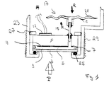
- Fig. 1 is a section through an inventive Relative pressure sensor shown.
- the heart of the Relative pressure sensor is shown in the Embodiment a capacitive ceramic Pressure measuring cell.
- This has a base body 1 and Measuring membrane 3 on.
- the base body 1 consists e.g. out Ceramics.
- the measuring membrane 3 can also be made of ceramic exist or e.g. made of sapphire.
- the measuring membrane 3 and Base bodies 1 are on the edge of which form a Measuring chamber 5 by means of a joint 7 pressure-tight and connected gastight.
- the measuring membrane 3 is sensitive to pressure, i.e. a pressure on them causes a deflection of the measuring diaphragm 3 from its Rest position ..
- the measuring membrane 3 closes the measuring chamber 5.
- An electrode 9 is located on the inside of the measuring membrane 3 and on an opposite inside of the Base body 1 is at least one counter electrode 11 arranged.
- the electrode 9 of the measuring membrane 3 is through the Joining point 7 electrically contacted and outside e.g. connected to ground.
- the counter electrode 11 of the Base body 1 is through base body 1 the outside electrically contacts and leads to an electronic arranged on the base body 1 Circuit 13.
- Form electrode 9 and counter electrode 11 forms a capacitor and the electronic circuit 13 the capacitance changes of the capacitor e.g. in a itself accordingly changing electrical voltage.
- the pressure P causes one pressure-dependent deflection of the measuring membrane 3 by one Converter is converted into an electrical measured variable.
- the electrical measured variable is e.g. a tension.
- the measurand is over Connection lines 14 for further processing and / or Evaluation available.
- the transducer has these types of measuring cells strain gauges attached to the measuring membrane.
- the measuring chamber can also be used for these measuring cells Base body on which the measuring membrane with its outer edge is attached, and the measuring membrane itself be formed.
- the base body 1 has a through hole, in which a tube 15 is inserted.
- a resilient Bellows 17 On a body facing away from the body The end of the tube 15 is a resilient Bellows 17 arranged on the all sides during operation from the outside a reference pressure R acts. This is shown in Fig. 1 Arrows marked.
- the interior of the bellows 17 is over the tube 15 is connected to the measuring chamber 5.
- the Measuring chamber 5, the tube 15 and the bellows 17 are with one Gas, e.g. filled with air.
- the gas-filled room is hermetically sealed and therefore safe Protect moisture and / or contaminants.
- the bellows 17 is compressible. Hence, that is Internal volume depending on the outside of the bellows 17 acting reference pressure R.
- the reference pressure R increases the bellows 17 is compressed and the pressure inside the Bellows 17 rises until bellows 17 enters Balance of forces. Because the interior of the bellows 17 is connected to the measuring chamber 3 via the tube 15, an internal pressure prevailing in the measuring chamber 5 is the same the pressure inside the bellows 17 depending from the reference pressure R.
- the two membranes 19, 21 are preferably as shown in Fig. 1 as Corrugated membranes formed.
- This has the advantage that the Inner volume of the bellows 17 at an average reference pressure is relatively small, but the bellows 17 by a Deflection of both membranes away from each other Internal volume can increase significantly. That means for one that only a small amount of gas is present, the expands with temperature, and second, that one temperature-related gas expansion from the bellows 17 is recorded without the pressure in the Inside the bellows 17 and thus in the measuring chamber 5 at one certain reference pressure R sets changes significantly.
- the relative pressure sensor has a housing 23 in which the capacitive ceramic measuring cell is clamped.
- the housing 23 has an opening with a radial inward shoulder on which the Measuring membrane 3 with an outer pressure-insensitive edge with the interposition of a seal 25, e.g. an O-ring, lies on.
- a seal 25 e.g. an O-ring
- On a side facing away from the measuring membrane The measuring cell is a threaded ring 27 in the housing 23 screwed through which the measuring cell against the seal 25th is pressed.
- an external thread 29 is provided on the housing 23. Other types of attachment can also be used.
- FIG. 2 is a further pressure measuring cell with a gas-filled spring-elastic bellows 18 shown.
- the Pressure measuring cell can be housed in the same way be installed, such as that shown in Fig. 1 Pressure measuring cell.
- the two pressure measuring cells differ only by the shape and arrangement of the bellows 17 or 18.
- the base body 1 has a through hole.
- the bellow 18 consists of a thin, slightly curved corrugated membrane. An outer edge of the bellows 18 is with one of the Measuring membrane 3 facing away from the back of the base body 1 connected.
- the corrugated membrane closes with the base body 1 a small volume and covers the continuous one Drilling.
- the interiors of the bellows 18, the bore and the Measuring chamber 5 form a single gas-tight sealed Cavity that is filled with a gas, e.g. Air is filled.
- a gas e.g. Air is filled.
- the Reference pressure acts on the bellows 18 from the outside. The Operation corresponds to that of the previously described Embodiment.
- the bellows 17, 18 is a Stiffness that is small compared to one Stiffness of the measuring membrane 3.
- the stiffness of Measuring membrane 3 and bellows 17, 18 is through the Material properties of the materials used, their Thickness and its shape determined. The sensitivity of the relative pressure sensor and thus at best achievable measurement accuracy is due to the rigidity of the Measuring membrane 3 limited.
- Spring-elastic materials are particularly suitable, especially Metals such as a copper beryllium alloy. It is but also a stainless steel or a resilient plastic applicable. Such resilient materials offer further the advantage of a very low hysteresis Deformations.
- the stiffness of bellows 17, 18 and measuring membrane 3 can be in Form of a pressure / volume constant specified quantitatively become. There is an acting pressure on one change in the inner volume of the bellows caused by this pressure or of the internal chamber volume.
- the pressure / volume constant can either be experimental or approximate can be determined by calculation. With suitable dimensioning the pressure / volume constant can be increased by a factor of 1000 to 10000 less than that of the measuring membrane 3.
- a calibration via pressure and temperature will also be carried out with the relative pressure sensors according to the invention.
- these relative pressure sensors can record relatively large deviations of an average reference pressure from the predetermined average reference pressure without leaving a linear range of the sensor characteristic. Within this linear range, an adjustment of the zero point of the relative pressure sensor on site is sufficient to obtain the same measuring accuracy as is achieved with the predetermined mean reference pressure.
- a relative pressure sensor calibrated at sea level can therefore also be used in the mountains, for example at a height of 2000 m, without any loss of accuracy.
Landscapes
- Physics & Mathematics (AREA)
- General Physics & Mathematics (AREA)
- Chemical & Material Sciences (AREA)
- Engineering & Computer Science (AREA)
- Ceramic Engineering (AREA)
- Measuring Fluid Pressure (AREA)
Priority Applications (6)
| Application Number | Priority Date | Filing Date | Title |
|---|---|---|---|
| DE59914223T DE59914223D1 (de) | 1999-07-01 | 1999-07-01 | Relativdrucksensor |
| EP19990112538 EP1065488B1 (fr) | 1999-07-01 | 1999-07-01 | Capteur de pression relative |
| US09/604,359 US6425291B1 (en) | 1999-07-01 | 2000-06-27 | Relative-pressure sensor having a gas-filled bellows |
| JP2000196988A JP3325879B2 (ja) | 1999-07-01 | 2000-06-29 | 相対圧センサ |
| CNB001199048A CN1135376C (zh) | 1999-07-01 | 2000-06-30 | 相对压力传感器 |
| CA 2313313 CA2313313C (fr) | 1999-07-01 | 2000-06-30 | Capteur de pression relative |
Applications Claiming Priority (1)
| Application Number | Priority Date | Filing Date | Title |
|---|---|---|---|
| EP19990112538 EP1065488B1 (fr) | 1999-07-01 | 1999-07-01 | Capteur de pression relative |
Publications (2)
| Publication Number | Publication Date |
|---|---|
| EP1065488A1 true EP1065488A1 (fr) | 2001-01-03 |
| EP1065488B1 EP1065488B1 (fr) | 2007-02-28 |
Family
ID=8238469
Family Applications (1)
| Application Number | Title | Priority Date | Filing Date |
|---|---|---|---|
| EP19990112538 Expired - Lifetime EP1065488B1 (fr) | 1999-07-01 | 1999-07-01 | Capteur de pression relative |
Country Status (5)
| Country | Link |
|---|---|
| EP (1) | EP1065488B1 (fr) |
| JP (1) | JP3325879B2 (fr) |
| CN (1) | CN1135376C (fr) |
| CA (1) | CA2313313C (fr) |
| DE (1) | DE59914223D1 (fr) |
Cited By (4)
| Publication number | Priority date | Publication date | Assignee | Title |
|---|---|---|---|---|
| DE102004051219A1 (de) * | 2004-10-20 | 2006-05-04 | Endress + Hauser Gmbh + Co. Kg | Druckmessaufnehmer |
| DE102009028488A1 (de) | 2009-08-12 | 2011-02-17 | Endress + Hauser Gmbh + Co. Kg | Relativdrucksensor |
| US12188887B2 (en) | 2018-11-02 | 2025-01-07 | Innogized Technologies, Inc. | Material property testing system and method |
| US12487125B2 (en) | 2023-03-31 | 2025-12-02 | Innogized Technologies, Inc. | Material property and environmental characterization by photodiode systems and methods |
Families Citing this family (17)
| Publication number | Priority date | Publication date | Assignee | Title |
|---|---|---|---|---|
| JP4828030B2 (ja) * | 2001-02-27 | 2011-11-30 | ミネベア株式会社 | 高温計測用半導体式圧力センサ |
| JP4925522B2 (ja) * | 2001-04-27 | 2012-04-25 | 京セラ株式会社 | 圧力検出装置用パッケージ |
| DE10234754A1 (de) * | 2002-07-30 | 2004-02-19 | Endress + Hauser Gmbh + Co. Kg | Differenzdrucksensor mit symmetrischem Trennkörperfehler |
| DE102007040080A1 (de) | 2007-08-24 | 2009-02-26 | BSH Bosch und Siemens Hausgeräte GmbH | Vorrichtung und Verfahren zur Ermittlung eines Füllstandes innerhalb eines Laugenbehälters einer Waschmaschine |
| WO2009079803A1 (fr) * | 2007-12-20 | 2009-07-02 | Inficon Gmbh | Agencement pour une cellule de mesure de pression à membrane |
| KR100981928B1 (ko) * | 2008-03-17 | 2010-09-13 | (주)와이즈산전 | 정전용량 방식 복합 압력계 |
| EP2463635B2 (fr) * | 2010-12-07 | 2016-01-06 | VEGA Grieshaber KG | Cellule de mesure de pression |
| DE102011017265A1 (de) * | 2011-04-15 | 2012-10-18 | Armaturenbau Gmbh | Referenzdruckmanometer |
| DE102011102837A1 (de) * | 2011-05-30 | 2012-12-06 | Epcos Ag | Drucksensor und Verfahren zur Herstellung eines Drucksensors |
| CN104114990B (zh) * | 2012-02-16 | 2016-08-31 | 北陆电气工业株式会社 | 压力传感器模块 |
| DE102013114608A1 (de) * | 2013-12-20 | 2015-07-09 | Endress + Hauser Gmbh + Co. Kg | Relativdrucksensor |
| CN104236787B (zh) * | 2014-09-05 | 2017-03-15 | 龙微科技无锡有限公司 | Mems差压传感器芯片及制作方法 |
| CN108529030B (zh) * | 2018-06-15 | 2024-03-01 | 江苏龙禾轻型材料有限公司 | 全接液焊接式内浮盘 |
| JP7105492B2 (ja) * | 2019-02-25 | 2022-07-25 | ヤマシンフィルタ株式会社 | 差圧検出装置 |
| CN115900046A (zh) * | 2021-09-30 | 2023-04-04 | 广东美的制冷设备有限公司 | 空调器 |
| CN118008658B (zh) * | 2024-04-08 | 2024-06-18 | 齐翔华利新材料有限公司 | 一种混流式水轮机及其使用方法 |
| CN120867888B (zh) * | 2025-09-26 | 2025-12-30 | 成都凯天电子股份有限公司 | 一种自动起动器用可调节式真空膜盒组及其制作方法 |
Citations (3)
| Publication number | Priority date | Publication date | Assignee | Title |
|---|---|---|---|---|
| US4212209A (en) * | 1978-09-07 | 1980-07-15 | Honeywell Inc. | Differential pressure to electric current transducer employing a strain sensitive resistive pattern on a substrate having a high modulus of elasticity |
| US4425799A (en) * | 1982-06-03 | 1984-01-17 | Kavlico Corporation | Liquid capacitance pressure transducer technique |
| EP0524550A1 (fr) * | 1991-07-25 | 1993-01-27 | Fibronix Sensoren GmbH | Palpeur de pression relative rempli de gaz |
-
1999
- 1999-07-01 DE DE59914223T patent/DE59914223D1/de not_active Expired - Fee Related
- 1999-07-01 EP EP19990112538 patent/EP1065488B1/fr not_active Expired - Lifetime
-
2000
- 2000-06-29 JP JP2000196988A patent/JP3325879B2/ja not_active Expired - Fee Related
- 2000-06-30 CN CNB001199048A patent/CN1135376C/zh not_active Expired - Fee Related
- 2000-06-30 CA CA 2313313 patent/CA2313313C/fr not_active Expired - Fee Related
Patent Citations (3)
| Publication number | Priority date | Publication date | Assignee | Title |
|---|---|---|---|---|
| US4212209A (en) * | 1978-09-07 | 1980-07-15 | Honeywell Inc. | Differential pressure to electric current transducer employing a strain sensitive resistive pattern on a substrate having a high modulus of elasticity |
| US4425799A (en) * | 1982-06-03 | 1984-01-17 | Kavlico Corporation | Liquid capacitance pressure transducer technique |
| EP0524550A1 (fr) * | 1991-07-25 | 1993-01-27 | Fibronix Sensoren GmbH | Palpeur de pression relative rempli de gaz |
Cited By (7)
| Publication number | Priority date | Publication date | Assignee | Title |
|---|---|---|---|---|
| DE102004051219A1 (de) * | 2004-10-20 | 2006-05-04 | Endress + Hauser Gmbh + Co. Kg | Druckmessaufnehmer |
| DE102004051219B4 (de) * | 2004-10-20 | 2013-03-14 | Endress + Hauser Gmbh + Co. Kg | Druckmessaufnehmer |
| DE102009028488A1 (de) | 2009-08-12 | 2011-02-17 | Endress + Hauser Gmbh + Co. Kg | Relativdrucksensor |
| WO2011018311A1 (fr) | 2009-08-12 | 2011-02-17 | Endress+Hauser Gmbh+Co.Kg | Capteur de pression relative |
| US8770032B2 (en) | 2009-08-12 | 2014-07-08 | Endress + Hauser Gmbh +Co. Kg | Relative pressure sensor |
| US12188887B2 (en) | 2018-11-02 | 2025-01-07 | Innogized Technologies, Inc. | Material property testing system and method |
| US12487125B2 (en) | 2023-03-31 | 2025-12-02 | Innogized Technologies, Inc. | Material property and environmental characterization by photodiode systems and methods |
Also Published As
| Publication number | Publication date |
|---|---|
| DE59914223D1 (de) | 2007-04-12 |
| EP1065488B1 (fr) | 2007-02-28 |
| CA2313313C (fr) | 2005-04-12 |
| CN1135376C (zh) | 2004-01-21 |
| CN1290857A (zh) | 2001-04-11 |
| JP3325879B2 (ja) | 2002-09-17 |
| JP2001033332A (ja) | 2001-02-09 |
| CA2313313A1 (fr) | 2001-01-01 |
Similar Documents
| Publication | Publication Date | Title |
|---|---|---|
| EP1065488B1 (fr) | Capteur de pression relative | |
| EP1128172B1 (fr) | Capteur de pression | |
| EP0759547B1 (fr) | Capteur de pression | |
| EP0524550B1 (fr) | Palpeur de pression relative rempli de gaz | |
| EP1883798B1 (fr) | Capteur de pression utilisant un corps de capteur compressible | |
| US5712428A (en) | Pressure sensor with a solid to minimize temperature-related measurement error | |
| DE4335588C2 (de) | Drucksensor | |
| DE10392622T5 (de) | Barometrischer Drucksensor | |
| EP1409979A1 (fr) | Capteur de pression | |
| DE10227479A1 (de) | Druckmeßgerät | |
| US4499773A (en) | Variable capacitance pressure transducer | |
| EP1070948A1 (fr) | Capteur de pression relative | |
| EP1631804A1 (fr) | Capteur de pression muni d'une protection anti-humidite | |
| EP1325294B1 (fr) | Capteur de mesure de pression a membrane, comprenant une garniture avec rondelle-ressort contre la deformation | |
| US7093495B2 (en) | Pressure sensor | |
| DE10043630A1 (de) | Druckmeßzelle | |
| EP2098845B1 (fr) | Capteur de pression en céramique | |
| WO2002031460A1 (fr) | Cellule de mesure de pression | |
| DE102018100716B3 (de) | Druckmessgerät | |
| DE10120069B4 (de) | Scheibenförmiges Siliziumsensorelement für einen Druckfühler sowie Druckfühler unter Verwendung eines derartigen Siliziumsensorelements | |
| DE102019124083B3 (de) | Absolutdruckmessgerät mit einer relativ messenden Druckmesszelle | |
| DE102008009503A1 (de) | Verfahren zur Gasdruckmessung in evakuierten Verglasungen nach dem Prinzip des Membran-Vakuummeters | |
| DE19753874A1 (de) | Kraftsensor | |
| DE4315041C1 (de) | Sensorzelle | |
| WO2003081194A1 (fr) | Capteur de pression destine notamment a la determination capacitive de la pression absolue |
Legal Events
| Date | Code | Title | Description |
|---|---|---|---|
| PUAI | Public reference made under article 153(3) epc to a published international application that has entered the european phase |
Free format text: ORIGINAL CODE: 0009012 |
|
| AK | Designated contracting states |
Kind code of ref document: A1 Designated state(s): DE FR GB IT |
|
| AX | Request for extension of the european patent |
Free format text: AL;LT;LV;MK;RO;SI |
|
| 17P | Request for examination filed |
Effective date: 20010118 |
|
| AKX | Designation fees paid |
Free format text: DE FR GB IT |
|
| RAP1 | Party data changed (applicant data changed or rights of an application transferred) |
Owner name: ENDRESS + HAUSER GMBH + CO.KG. |
|
| 17Q | First examination report despatched |
Effective date: 20050622 |
|
| GRAP | Despatch of communication of intention to grant a patent |
Free format text: ORIGINAL CODE: EPIDOSNIGR1 |
|
| GRAS | Grant fee paid |
Free format text: ORIGINAL CODE: EPIDOSNIGR3 |
|
| GRAA | (expected) grant |
Free format text: ORIGINAL CODE: 0009210 |
|
| AK | Designated contracting states |
Kind code of ref document: B1 Designated state(s): DE FR GB IT |
|
| REG | Reference to a national code |
Ref country code: GB Ref legal event code: FG4D Free format text: NOT ENGLISH |
|
| REF | Corresponds to: |
Ref document number: 59914223 Country of ref document: DE Date of ref document: 20070412 Kind code of ref document: P |
|
| GBT | Gb: translation of ep patent filed (gb section 77(6)(a)/1977) |
Effective date: 20070517 |
|
| ET | Fr: translation filed | ||
| PLBE | No opposition filed within time limit |
Free format text: ORIGINAL CODE: 0009261 |
|
| STAA | Information on the status of an ep patent application or granted ep patent |
Free format text: STATUS: NO OPPOSITION FILED WITHIN TIME LIMIT |
|
| 26N | No opposition filed |
Effective date: 20071129 |
|
| PGFP | Annual fee paid to national office [announced via postgrant information from national office to epo] |
Ref country code: DE Payment date: 20080722 Year of fee payment: 10 |
|
| PGFP | Annual fee paid to national office [announced via postgrant information from national office to epo] |
Ref country code: IT Payment date: 20080724 Year of fee payment: 10 Ref country code: FR Payment date: 20080715 Year of fee payment: 10 |
|
| PGFP | Annual fee paid to national office [announced via postgrant information from national office to epo] |
Ref country code: GB Payment date: 20080722 Year of fee payment: 10 |
|
| GBPC | Gb: european patent ceased through non-payment of renewal fee |
Effective date: 20090701 |
|
| REG | Reference to a national code |
Ref country code: FR Ref legal event code: ST Effective date: 20100331 |
|
| PG25 | Lapsed in a contracting state [announced via postgrant information from national office to epo] |
Ref country code: FR Free format text: LAPSE BECAUSE OF NON-PAYMENT OF DUE FEES Effective date: 20090731 |
|
| PG25 | Lapsed in a contracting state [announced via postgrant information from national office to epo] |
Ref country code: GB Free format text: LAPSE BECAUSE OF NON-PAYMENT OF DUE FEES Effective date: 20090701 |
|
| PG25 | Lapsed in a contracting state [announced via postgrant information from national office to epo] |
Ref country code: DE Free format text: LAPSE BECAUSE OF NON-PAYMENT OF DUE FEES Effective date: 20100202 |
|
| PG25 | Lapsed in a contracting state [announced via postgrant information from national office to epo] |
Ref country code: IT Free format text: LAPSE BECAUSE OF NON-PAYMENT OF DUE FEES Effective date: 20090701 |